EP1052324A2 - Aiguille de machine à coudre avec chas à lèvres décalées - Google Patents
Aiguille de machine à coudre avec chas à lèvres décalées Download PDFInfo
- Publication number
- EP1052324A2 EP1052324A2 EP00106098A EP00106098A EP1052324A2 EP 1052324 A2 EP1052324 A2 EP 1052324A2 EP 00106098 A EP00106098 A EP 00106098A EP 00106098 A EP00106098 A EP 00106098A EP 1052324 A2 EP1052324 A2 EP 1052324A2
- Authority
- EP
- European Patent Office
- Prior art keywords
- eye
- sewing machine
- machine needle
- central axis
- thread
- Prior art date
- Legal status (The legal status is an assumption and is not a legal conclusion. Google has not performed a legal analysis and makes no representation as to the accuracy of the status listed.)
- Granted
Links
- 238000009958 sewing Methods 0.000 title claims abstract description 122
- 230000007704 transition Effects 0.000 claims description 9
- 230000001154 acute effect Effects 0.000 claims description 7
- 239000000463 material Substances 0.000 description 26
- 238000000034 method Methods 0.000 description 5
- 230000015572 biosynthetic process Effects 0.000 description 3
- 239000002360 explosive Substances 0.000 description 2
- 239000000835 fiber Substances 0.000 description 2
- 238000010792 warming Methods 0.000 description 2
- 230000002146 bilateral effect Effects 0.000 description 1
- 238000000576 coating method Methods 0.000 description 1
- 230000003247 decreasing effect Effects 0.000 description 1
- 238000010438 heat treatment Methods 0.000 description 1
- 230000001771 impaired effect Effects 0.000 description 1
- 238000003780 insertion Methods 0.000 description 1
- 230000037431 insertion Effects 0.000 description 1
- 238000004519 manufacturing process Methods 0.000 description 1
- 238000002844 melting Methods 0.000 description 1
- 230000008018 melting Effects 0.000 description 1
- 239000003973 paint Substances 0.000 description 1
- 230000000149 penetrating effect Effects 0.000 description 1
- 230000035515 penetration Effects 0.000 description 1
- 230000000284 resting effect Effects 0.000 description 1
- 239000012209 synthetic fiber Substances 0.000 description 1
- 229920002994 synthetic fiber Polymers 0.000 description 1
- 239000004753 textile Substances 0.000 description 1
Images

Classifications
-
- D—TEXTILES; PAPER
- D05—SEWING; EMBROIDERING; TUFTING
- D05B—SEWING
- D05B85/00—Needles
Definitions
- the invention relates to a sewing machine needle, in particular for high-speed sewing machines.
- Stitches of 5000 stitches / min and more are today the rule for industrial sewing machines. With certain Applications are even up to 8000 stitches / min achieved more.
- the needle When the needle is inserted into the material, it opens a stitch hole and pulls the thread (sewing thread) into the stitch hole on. If the number of stitches is very high, the opening of the At most a very short period of time about 0.5 ms or less.
- the taphole opening time is the duration from the first touch of the sewing material through the needle tip up to the eye passage. Through the almost explosive opening of the tap hole there is high frictional force between the sewing machine needle and the sewing material. Therefore, relatively large puncture forces can occur what is required for the needle insertion required energy requirements increased.
- Another problem with sewing needles is especially at higher machine speeds that mechanical stress on the sewing needle. Rotating masses in The sewing machine can cause vibrations that especially on the sewing machine needle clamped on one side impact. Also act on the needle as a result of thread tension and deflection when hitting the sewing machine needle on the material and as a result of operational influences other powers. This in turn leads to the desire sewing machine needles as thick as possible, the have sufficient rigidity. Both demands a sewing machine needle as thin as possible to protect the Material and to avoid excessive needle heating to use and a sewing machine needle as thick as possible use the required stability at high sewing speeds to achieve, contradict each other.
- a sewing machine needle is known from US Pat. No. 4,037,641 known with a straight shaft that is near its tip has an eye that runs transversely to its central axis.
- the eye is in the axial direction by two opposite one another ⁇ hrstege limits, both essentially lie on the central axis of the sewing machine needle.
- To the ⁇ hr closes in the direction of the clamping part of the Shaft, a thread groove.
- On the opposite Side of the sewing machine needle is another short one, in In the direction of the groove to be run on the needle tip, which ends flat in the immediate vicinity of the eye. Closes on the same side of the sewing machine needle a groove at the eye in the direction of the clamping part on.
- the one between the thread gutter and the fillet arranged eye bridge is rounded on the eye side and serves to pull the thread into an open stitch hole.
- the eye area of the sewing machine needle is transverse to the central axis and dimensioned in the opening direction of the eye that the open hole is relatively large. Surrender the above relationships.
- the sewing machine needle according to the invention has a Essentially just trained shaft. This one has no offset area in which parts of the shaft laterally could protrude beyond its undiminished contour. Thereby it is possible that the penetrating material Sewing machine needle the flanks of the stitch hole created not laterally deflected, which accelerates the Sewing material in the lateral direction and this may result Friction is avoided.
- the sewing machine needle according to the invention has two spaced-apart eye bridges that run against the central axis the sewing machine needle.
- the offset is preferably such that the to the clamping part indicative ⁇ hrsteg a barrier-free transition in the eye releases. It is thus on the side facing away from the thread groove Side of the sewing machine needle arranged. In contrast is towards the tip of the sewing machine needle pointing eye bridge straight to the other side of the eye transferred. It is approximately in the imaginary extension of the thread groove arranged.
- the offset of the eye bridges against each other allows a reduction in the amount of Sewing machine needle in the eye area compared to the nominal size the sewing machine needle without any loss in principle the needle stiffness.
- the height of the sewing machine needle is perpendicular to the central axis and in one through the Eye leading direction measured.
- the puncture force is lower, resulting in a lower power requirement to drive the sewing machine needle. Besides, that is too emerging needle warming due to decreased Less friction. At the same time, there is a gentle on the material Tap hole opening with high thread protection. The likelihood of skipped stitches and thread breaks is significantly reduced.
- the eyelets are rounded and free of edges, the rounding of the top, i.e. to the clamping part indicative eye bridge at a desired eye bridge thickness preferably a radius of 50% of the nominal needle size of 20% of the nominal needle size. This leads overall to a good thread run.
- the eye bridges are preferably against one another Distance offset transversely to the central axis, the minimum 40% to a maximum of 50% of the nominal needle size. This allows the thread protection in the elongated longitudinal passage of the thread can be optimized through the eye.
- the eyelets are preferably about half as thick as the nominal nominal size of the sewing machine needle. Thereby there is both the possibility of a slim design the sewing machine needle in the ear area, as well as one good stability and rigidity.
- the tip of the sewing machine needle can be on a central axis lying at the same time approximately in the middle through the eye leads. If necessary, the tip of the sewing machine needle however, they can also be arranged offset with respect to the central axis. Regardless of this, it is expedient to use the eye bridges in this way to order that an imaginary, going through the eye and straight line resting on the inner surfaces of the eye bridges encloses an acute angle with the central axis, which is less than 20 °.
- the eye bridge offset and at the same time the small acute angle of the so defined, through the eye bridge running tangents allow low friction of the thread on the sewing machine needle, even if the eye is in Axial direction (direction of the central axis) is relatively narrow.
- the friction can still be due to a concave design the eye bridges can be reduced.
- the sewing machine needle preferably has a relative short eye at which the measured in the axial direction Distance between the eye bridges about one to 1.1 times as much is large, like the nominal needle size. This gives one precise guidance of the thread and can possibly too lead to a reduction in the required penetration depth.
- the eye walls preferably have a non-flat face on the eye side Walls open, with the eye walls facing both eye openings diverge. It can also be between the eye walls included angles measured transversely to the central axis vary along the central axis. This favors the The thread runs through the eye and reduces its friction. At the same time the bilateral support of the Stitch interlocking ensures the required thread loop.
- a groove In the neighborhood of the eye can on one of the thread gutter side of the sewing machine needle a groove be provided.
- the fillet preferably goes without a sharp edge in the eye over what the thread guard is useful.
- a preferred embodiment of the sewing machine needle has eye walls that do not have the to the clamping part projecting eye bridge. This results in a relatively small needle cross section in the cross area and a comparatively slow opening of the tap hole and a appropriate protection of the sewing material.
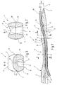
- FIG. 1 shows a sewing machine needle 1, the shaft 2 of which is not illustrated in FIG. 1 and adjoining shaft 2 on the left Clamping part up to a point 3 along a central axis 4 extends.
- the tip 3 is preferably on the Central axis 4.
- the shaft 2 is, as illustrated in FIG. 3, on its upper side in the figure 5 and its lower side 6 is substantially flattened. Arranged between the side 5 and the side 6 Side surfaces 7, 8 are convexly curved.
- the cross section the sewing machine needle 1 is weakened in this area Shaft 2, apart from the convex curvature the side surfaces 7, 8, approximately square.
- the nominal Needle size is in the shaft area above the fillet in the direction of the clamping part by the diameter of the Sewing machine needle 1 determined.
- the height of the eye 11 is determined by the distance of pages 5 and 6 to each other.
- the sewing machine needle 1 is preferably something weaker than in the un weakened area of the Shaft 2, which is shown on the left in Figure 1.
- the diminution the thickness of the shaft 2 is in the eye area Embodiment at about 5% to 20%, preferably about 10% in terms of the distance between side 5 and page 6 in the undiminished area.
- the eye 11 is designated by the central axis 4 Axial direction limited by two eye webs 12, 14, against the central axis 4 in the direction of the thread guard 21 or groove 34 are offset. On their end facing the eye 11 are the eye webs 12, 14 each rounded approximately semicircular, the radius of curvature each relatively exactly half the thickness of each ⁇ hrstegs 12, 14 corresponds.
- the in the transverse direction, i.e. in Figure 1 vertically measured offset between the two ⁇ hrstegen 12, 14 is preferably about 40% to 50% of nominal needle size. So that the ⁇ hrstege 12, 14th with their bottom surfaces 16, 17 each approximately on the central axis 4.
- the rounded eye-side end of the eye bridge 12 goes from its circular arc shape at one point 15 kink and heel-free in a stretched and, as from Figure 1 can be seen, 4 concave with respect to the central axis Floor area 16 over.
- a tangent can be created on the central axis 4 lies or with this a very acute angle of a few degrees.
- the ⁇ hrsteg 14 also has a concavely rounded bottom surface 17 on the thread running side.
- a transition point 18 between the floor surface 17 and the rounded end of the eye bridge 14 lies approximately on the central axis 4 and a tangent at this point is correct approximately coincides with the central axis 4.
- the eye 11 is relatively narrow. In the axial direction, which is determined by the central axis 4 is the by the axial removal of the ends of the eye webs 12, 14 certain length of the eye preferably about 1 to 1.1 times the nominal needle size of the sewing machine needle 1. This enables good thread guidance. Despite that relatively short eye 11 is due to the offset of the ⁇ hrstege 12, 14 reached an elongated thread. It Embodiments are also possible in which the length of the ear larger or smaller than 1 to 1.1 times that nominal needle size.
- a thread groove 21 directed away from the tip 3 formed by two side walls 22, 23 ( Figure 3) is limited. These have two essentially flat, mutually parallel flanks on the side 6 are partially touched.
- the thread groove 21 also has an essentially plan floor 24 that in some Distance runs parallel to the central axis 4. In one approximately the distance from the eye 11 corresponding to the needle size The bottom 24 then begins in the bottom surface 16 of the eye bridge 12 to pass. The floor surface 16 then runs in acute angle to the central axis 4.
- the eye 11 is, as can be seen in particular from FIG. 2, delimited by two eye walls 26, 27, the thickness of which measured across the eye 11 (Figure 2, line 28), respectively is slightly less than the clear width of the eye in the area this line 28 passing through the central axis 4.
- the flanks of the thread groove 21 go with the confluence of the Thread groove 21 in the eye 11 seamlessly in inner surfaces 29, 30 the eye walls 26, 27 over. It can be between the Flanks of the thread groove 21 or the inner surfaces 29, 30 included angles measured transversely to the central axis 4 change along the central axis 4.
- a groove 34 is provided in the shaft 2. This lies opposite the thread groove 21.
- the fillet 34 has one shown in Figure 3, rounded and rounded back 35 merging into the side surfaces 7, 8.
- the rounded transitions serve to relieve and protect of the seam material.
- FIG. 1 Transition area 36 is formed by the eye bridge 12, being the transition from its rounded end to the outside is formed without edges. From the transition point of the rounded end of ⁇ hrstegs 12 to the Extend the outside or side 5 of the sewing machine needle 1 the eye walls 26, 27 at the same height, without sideways or to protrude upwards in FIG. 1 over the eye bridge 12.
- the upper end of the eye 11 in FIG. 1 is the same Height with the entire side 6 of the sewing machine needle 1 lies, the upper end of the eye 11 is arranged somewhat lower than page 5 at least, in the undiminished Shaft area.
- the one shown in FIG. height of the parallel to the line 9 to be measured Eye walls 26, 27 is slightly less than the nominal needle size.
- the sewing machine needle 1 described so far works as follows:
- the sewing machine needle 1 becomes faster when sewing follows periodically oscillating along its central axis 4 moved back and forth.
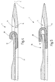
- the sewing machine needle 1 moves first of all at a right angle in front of its tip 3 the central axis 4 arranged sewing material is a through the eye 11 running thread 38 (sewing thread) first stretched passed through the thread groove 21 and the groove 32.
- the thread 38 is under tension so that it selectively on the bottom surfaces 16, 17 of the earpieces 12, 14 is present. Due to their concave formation, they become flat Plant avoided.
- the sewing machine needle 1 is with the eye 11 through the Stitched material, the thread 38 around the eye bridge 12 sets.
- the upper section of the thread 38 in FIG. 4 has only a low relative speed in relation to the sewing material and is more or less in Quiet.
- the advancing sewing machine needle 1 pulls as in Figure 4 is indicated by arrows in the thread groove 21 lying section of thread 38 at very high speed to. Too much friction between that Thread 38 and the sewing material is due to the considerable depth the thread groove 21 largely minimized. Too much friction at the ⁇ hrsteg 12 is due to its rounding and its minimized considerable thickness, e.g. about with the Diameter of the thread 38 matches.
- the sewing machine needle returns as the sewing process continues 1 their direction of movement again, as in Figure 5 is illustrated.
- the one from the sewing machine needle 1 thread 38 inserted into the sewing material now lifts from it ⁇ hrsteg 12 from.
- Figure 6 A loop 39 is formed by one Gripper 40 can be added for seam formation. The exact formation of this sling is for a working one Sewing process crucial.
- the Sewing machine needle 1 then passes through again in the return stroke the puncture hole.
- the thread runs at high speed for wrapping the bobbin case in the opposite direction subtracted from the needle movement. Is the sewing machine needle 1 pulled out of the tap hole and the thread 38 tightened, the process is repeated again.
- the sewing machine needle 1 has an axial direction of two eye bridges 12, 14 limited eye 11, which in Axial direction (central axis 4) is relatively short is. Its length is not much greater than the nominal thickness the sewing machine needle 1. Eyelets 12, 14 are offset from one another, each eye web 12, 14 is about half as thick as the sewing machine needle 1 in the area of the eye 11. Thus becomes a stable and slim Sewing machine needle 1 created due to their Slenderness puncture holes opens relatively slowly and therefore sews gently even with very high numbers of stitches enables an almost fully protected thread run.
Landscapes
- Engineering & Computer Science (AREA)
- Textile Engineering (AREA)
- Sewing Machines And Sewing (AREA)
Applications Claiming Priority (2)
| Application Number | Priority Date | Filing Date | Title |
|---|---|---|---|
| DE19921914A DE19921914C2 (de) | 1999-05-12 | 1999-05-12 | Nähmaschinennadel mit versetzten Öhrstegen |
| DE19921914 | 1999-05-12 |
Publications (3)
| Publication Number | Publication Date |
|---|---|
| EP1052324A2 true EP1052324A2 (fr) | 2000-11-15 |
| EP1052324A3 EP1052324A3 (fr) | 2001-05-16 |
| EP1052324B1 EP1052324B1 (fr) | 2006-06-07 |
Family
ID=7907843
Family Applications (1)
| Application Number | Title | Priority Date | Filing Date |
|---|---|---|---|
| EP00106098A Expired - Lifetime EP1052324B1 (fr) | 1999-05-12 | 2000-03-30 | Aiguille de machine à coudre avec chas à lèvres décalées |
Country Status (5)
| Country | Link |
|---|---|
| US (1) | US6318280B1 (fr) |
| EP (1) | EP1052324B1 (fr) |
| JP (1) | JP2000325684A (fr) |
| DE (2) | DE19921914C2 (fr) |
| ES (1) | ES2261113T3 (fr) |
Cited By (1)
| Publication number | Priority date | Publication date | Assignee | Title |
|---|---|---|---|---|
| EP3153617A1 (fr) * | 2015-10-08 | 2017-04-12 | Groz-Beckert KG | Aiguille à coudre et procédé de couture |
Families Citing this family (5)
| Publication number | Priority date | Publication date | Assignee | Title |
|---|---|---|---|---|
| IL163209A (en) * | 2004-07-26 | 2009-08-03 | Yair Eilam | A sewing machine needle for sewing with a complex thread |
| US9693862B2 (en) * | 2012-07-31 | 2017-07-04 | Edwards Lifesciences Corporation | Holders for prosthetic heart valves |
| PL2896732T3 (pl) * | 2014-01-21 | 2016-12-30 | Igła szwalnicza z podwójną ochroną | |
| JP6876299B2 (ja) * | 2017-07-20 | 2021-05-26 | トヨタ車体株式会社 | ステッチ加工部品の製造方法及び縫い針 |
| DE102019219814A1 (de) | 2019-12-17 | 2021-06-17 | Pfaff Industriesysteme Und Maschinen Gmbh | Stichbildungswerkzeug-Baugruppe für eine Nähanlage sowie Nähanlage mit einer derartigen Baugruppe |
Family Cites Families (11)
| Publication number | Priority date | Publication date | Assignee | Title |
|---|---|---|---|---|
| DE2125074A1 (de) | 1970-06-03 | 1971-12-09 | Inst Ciezkiej Syntezy Orga | Verfahren zur Herstellung von Polyolefinen mit ungesättigten Bindungen |
| DE2412062A1 (de) * | 1973-03-13 | 1974-10-10 | Manta Fa | Naehnadel |
| US4037641A (en) * | 1976-07-16 | 1977-07-26 | The Singer Company | Method of fabricating sewing machine needles |
| DE2834738C2 (de) * | 1977-08-10 | 1984-07-12 | Wool Research Organisation of New Zealand (Inc.), Lincoln, Canterbury | Nadel für Tuftingmaschinen |
| DE7923552U1 (de) | 1979-01-25 | 1980-01-24 | Wool Research Organisation Of New Zealand Inc., Canterbury (Neuseeland) | Nadel fuer tufting-, naeh-, heftmaschinen u.dgl. |
| DE3027534A1 (de) * | 1980-07-21 | 1982-02-18 | Josef 5100 Aachen Zocher | Naehmaschinen-nadel |
| US4458614A (en) * | 1982-01-08 | 1984-07-10 | Organ Needle Co. Ltd. | Sewing machine needle |
| NZ201452A (en) * | 1982-08-02 | 1985-12-13 | Wool Res Organisation | Tufting machine needle |
| DE9106591U1 (de) * | 1991-05-29 | 1991-07-11 | Singer Spezialnadelfabrik GmbH, 5102 Würselen | Nähmaschinennadel |
| DE69735842T2 (de) * | 1997-06-03 | 2007-04-19 | Groz-Beckert Kg | Tuftingnadel |
| US6062151A (en) * | 1998-09-09 | 2000-05-16 | Groz-Beckert Kg | Tufting needle with offset stem |
-
1999
- 1999-05-12 DE DE19921914A patent/DE19921914C2/de not_active Expired - Fee Related
-
2000
- 2000-03-30 EP EP00106098A patent/EP1052324B1/fr not_active Expired - Lifetime
- 2000-03-30 ES ES00106098T patent/ES2261113T3/es not_active Expired - Lifetime
- 2000-03-30 DE DE50012884T patent/DE50012884D1/de not_active Expired - Lifetime
- 2000-05-09 JP JP2000136279A patent/JP2000325684A/ja active Pending
- 2000-09-12 US US09/660,557 patent/US6318280B1/en not_active Expired - Lifetime
Cited By (4)
| Publication number | Priority date | Publication date | Assignee | Title |
|---|---|---|---|---|
| EP3153617A1 (fr) * | 2015-10-08 | 2017-04-12 | Groz-Beckert KG | Aiguille à coudre et procédé de couture |
| WO2017060056A1 (fr) | 2015-10-08 | 2017-04-13 | Groz-Beckert Kg | Aiguille de machine à coudre, procédé de fabrication d'une aiguille de machine à coudre et procédé de couture |
| TWI700409B (zh) * | 2015-10-08 | 2020-08-01 | 德商葛羅斯貝克公司 | 縫紉針、其製造方法及縫紉方法 |
| US10753024B2 (en) | 2015-10-08 | 2020-08-25 | Groz-Beckert Kg | Sewing machine needle, method for producing a sewing machine needle, and sewing method |
Also Published As
| Publication number | Publication date |
|---|---|
| US6318280B1 (en) | 2001-11-20 |
| EP1052324B1 (fr) | 2006-06-07 |
| ES2261113T3 (es) | 2006-11-16 |
| DE19921914A1 (de) | 2000-12-07 |
| EP1052324A3 (fr) | 2001-05-16 |
| DE50012884D1 (de) | 2006-07-20 |
| JP2000325684A (ja) | 2000-11-28 |
| DE19921914C2 (de) | 2001-10-25 |
Similar Documents
| Publication | Publication Date | Title |
|---|---|---|
| EP0082538A1 (fr) | Métier à tricoter pour la fabrication de peluche à poil coupé | |
| DE2834738C2 (de) | Nadel für Tuftingmaschinen | |
| EP1052323B1 (fr) | Aiguille de machine à coudre à chas mince | |
| EP1039003A1 (fr) | Aiguille à coulisse double | |
| EP1028185B1 (fr) | Aiguille de transfert pour le transfert de maille | |
| EP2896732B1 (fr) | Aiguille à coudre avec double nervurage | |
| DE19921914C2 (de) | Nähmaschinennadel mit versetzten Öhrstegen | |
| DE4333545C1 (de) | Atraumatische Nadel für chirurgische Nähmaschinen | |
| DE3642693C1 (de) | Hakennadel(auch Hakenroehrnadel)fuer Naeh-,Stick-,Heftmaschinen und dergl. | |
| EP1727931B1 (fr) | Aiguille à tufter gaufrée | |
| EP1182287A2 (fr) | Machine à coudre à point invisible | |
| DE3531464A1 (de) | Naehnadel | |
| EP1127973B1 (fr) | Aiguille de couture pour couture multidirectionnelle | |
| DE3027534A1 (de) | Naehmaschinen-nadel | |
| EP0591470A1 (fr) | Dispositif pour le serrage et guidage d'aiguilles a crochet pour un metier a crocheter. | |
| DE102005062177B3 (de) | Systemteil für ein Stricksystem und Strickmaschine | |
| DE102009004033B4 (de) | Nähmaschinennadel | |
| DE3920408A1 (de) | Fadenzufuhreinrichtung mit wenigstens einem fadenfuehrer fuer eine rundstrickmaschine | |
| DE3029333A1 (de) | Filznadel | |
| DE7306932U (de) | Gabelnadel | |
| DE19932288C2 (de) | Nähmaschinennadel mit verbesserter Schlingenbildung | |
| DE3512775C2 (fr) | ||
| DE4407606C1 (de) | Breithalter für eine Strickmaschine | |
| EP1460161B1 (fr) | Dispositif pour couper le fil arrière dans des machines à broder à navette | |
| DE102005004124A1 (de) | Doppelkettenstich-Nähmaschine |
Legal Events
| Date | Code | Title | Description |
|---|---|---|---|
| PUAI | Public reference made under article 153(3) epc to a published international application that has entered the european phase |
Free format text: ORIGINAL CODE: 0009012 |
|
| AK | Designated contracting states |
Kind code of ref document: A2 Designated state(s): CH DE ES FR GB IT LI |
|
| AX | Request for extension of the european patent |
Free format text: AL;LT;LV;MK;RO;SI |
|
| PUAL | Search report despatched |
Free format text: ORIGINAL CODE: 0009013 |
|
| AK | Designated contracting states |
Kind code of ref document: A3 Designated state(s): AT BE CH CY DE DK ES FI FR GB GR IE IT LI LU MC NL PT SE |
|
| AX | Request for extension of the european patent |
Free format text: AL;LT;LV;MK;RO;SI |
|
| 17P | Request for examination filed |
Effective date: 20011016 |
|
| AKX | Designation fees paid |
Free format text: CH DE ES FR GB IT LI |
|
| 17Q | First examination report despatched |
Effective date: 20021126 |
|
| GRAP | Despatch of communication of intention to grant a patent |
Free format text: ORIGINAL CODE: EPIDOSNIGR1 |
|
| GRAS | Grant fee paid |
Free format text: ORIGINAL CODE: EPIDOSNIGR3 |
|
| GRAA | (expected) grant |
Free format text: ORIGINAL CODE: 0009210 |
|
| AK | Designated contracting states |
Kind code of ref document: B1 Designated state(s): CH DE ES FR GB IT LI |
|
| PG25 | Lapsed in a contracting state [announced via postgrant information from national office to epo] |
Ref country code: IT Free format text: LAPSE BECAUSE OF FAILURE TO SUBMIT A TRANSLATION OF THE DESCRIPTION OR TO PAY THE FEE WITHIN THE PRESCRIBED TIME-LIMIT;WARNING: LAPSES OF ITALIAN PATENTS WITH EFFECTIVE DATE BEFORE 2007 MAY HAVE OCCURRED AT ANY TIME BEFORE 2007. THE CORRECT EFFECTIVE DATE MAY BE DIFFERENT FROM THE ONE RECORDED. Effective date: 20060607 |
|
| REG | Reference to a national code |
Ref country code: GB Ref legal event code: FG4D Free format text: NOT ENGLISH |
|
| REG | Reference to a national code |
Ref country code: CH Ref legal event code: EP |
|
| REG | Reference to a national code |
Ref country code: CH Ref legal event code: NV Representative=s name: KIRKER & CIE SA |
|
| REF | Corresponds to: |
Ref document number: 50012884 Country of ref document: DE Date of ref document: 20060720 Kind code of ref document: P |
|
| GBT | Gb: translation of ep patent filed (gb section 77(6)(a)/1977) |
Effective date: 20061023 |
|
| REG | Reference to a national code |
Ref country code: ES Ref legal event code: FG2A Ref document number: 2261113 Country of ref document: ES Kind code of ref document: T3 |
|
| ET | Fr: translation filed | ||
| PLBE | No opposition filed within time limit |
Free format text: ORIGINAL CODE: 0009261 |
|
| STAA | Information on the status of an ep patent application or granted ep patent |
Free format text: STATUS: NO OPPOSITION FILED WITHIN TIME LIMIT |
|
| 26N | No opposition filed |
Effective date: 20070308 |
|
| PGFP | Annual fee paid to national office [announced via postgrant information from national office to epo] |
Ref country code: CH Payment date: 20120326 Year of fee payment: 13 Ref country code: FR Payment date: 20120403 Year of fee payment: 13 |
|
| PGFP | Annual fee paid to national office [announced via postgrant information from national office to epo] |
Ref country code: GB Payment date: 20120322 Year of fee payment: 13 |
|
| PGFP | Annual fee paid to national office [announced via postgrant information from national office to epo] |
Ref country code: IT Payment date: 20120330 Year of fee payment: 13 |
|
| PGFP | Annual fee paid to national office [announced via postgrant information from national office to epo] |
Ref country code: ES Payment date: 20120327 Year of fee payment: 13 |
|
| REG | Reference to a national code |
Ref country code: CH Ref legal event code: PL |
|
| GBPC | Gb: european patent ceased through non-payment of renewal fee |
Effective date: 20130330 |
|
| REG | Reference to a national code |
Ref country code: FR Ref legal event code: ST Effective date: 20131129 |
|
| PG25 | Lapsed in a contracting state [announced via postgrant information from national office to epo] |
Ref country code: FR Free format text: LAPSE BECAUSE OF NON-PAYMENT OF DUE FEES Effective date: 20130402 Ref country code: CH Free format text: LAPSE BECAUSE OF NON-PAYMENT OF DUE FEES Effective date: 20130331 Ref country code: LI Free format text: LAPSE BECAUSE OF NON-PAYMENT OF DUE FEES Effective date: 20130331 Ref country code: GB Free format text: LAPSE BECAUSE OF NON-PAYMENT OF DUE FEES Effective date: 20130330 |
|
| PG25 | Lapsed in a contracting state [announced via postgrant information from national office to epo] |
Ref country code: IT Free format text: LAPSE BECAUSE OF NON-PAYMENT OF DUE FEES Effective date: 20130330 |
|
| REG | Reference to a national code |
Ref country code: ES Ref legal event code: FD2A Effective date: 20140606 |
|
| PG25 | Lapsed in a contracting state [announced via postgrant information from national office to epo] |
Ref country code: ES Free format text: LAPSE BECAUSE OF NON-PAYMENT OF DUE FEES Effective date: 20130331 |
|
| PGFP | Annual fee paid to national office [announced via postgrant information from national office to epo] |
Ref country code: DE Payment date: 20150119 Year of fee payment: 16 |
|
| REG | Reference to a national code |
Ref country code: DE Ref legal event code: R119 Ref document number: 50012884 Country of ref document: DE |
|
| PG25 | Lapsed in a contracting state [announced via postgrant information from national office to epo] |
Ref country code: DE Free format text: LAPSE BECAUSE OF NON-PAYMENT OF DUE FEES Effective date: 20161001 |