EP0270960B1 - Appareil de surveillance d'écoulement - Google Patents
Appareil de surveillance d'écoulement Download PDFInfo
- Publication number
- EP0270960B1 EP0270960B1 EP87117642A EP87117642A EP0270960B1 EP 0270960 B1 EP0270960 B1 EP 0270960B1 EP 87117642 A EP87117642 A EP 87117642A EP 87117642 A EP87117642 A EP 87117642A EP 0270960 B1 EP0270960 B1 EP 0270960B1
- Authority
- EP
- European Patent Office
- Prior art keywords
- housing
- switch
- flow monitor
- protective sleeve
- pipeline section
- Prior art date
- Legal status (The legal status is an assumption and is not a legal conclusion. Google has not performed a legal analysis and makes no representation as to the accuracy of the status listed.)
- Expired - Lifetime
Links
- 230000001681 protective effect Effects 0.000 claims abstract description 32
- 238000007789 sealing Methods 0.000 claims description 4
- 229910001369 Brass Inorganic materials 0.000 claims description 2
- 239000010951 brass Substances 0.000 claims description 2
- 239000000463 material Substances 0.000 claims description 2
- 230000013011 mating Effects 0.000 claims 1
- 229920003002 synthetic resin Polymers 0.000 claims 1
- 239000000057 synthetic resin Substances 0.000 claims 1
- 235000014676 Phragmites communis Nutrition 0.000 abstract description 7
- 238000004140 cleaning Methods 0.000 description 8
- 238000011109 contamination Methods 0.000 description 3
- 238000012423 maintenance Methods 0.000 description 3
- 210000003746 feather Anatomy 0.000 description 1
- 239000012530 fluid Substances 0.000 description 1
- 238000009434 installation Methods 0.000 description 1
- 239000002245 particle Substances 0.000 description 1
- 230000002093 peripheral effect Effects 0.000 description 1
- 230000008439 repair process Effects 0.000 description 1
Images
Classifications
-
- G—PHYSICS
- G01—MEASURING; TESTING
- G01P—MEASURING LINEAR OR ANGULAR SPEED, ACCELERATION, DECELERATION, OR SHOCK; INDICATING PRESENCE, ABSENCE, OR DIRECTION, OF MOVEMENT
- G01P13/00—Indicating or recording presence, absence, or direction, of movement
- G01P13/0006—Indicating or recording presence, absence, or direction, of movement of fluids or of granulous or powder-like substances
- G01P13/0026—Indicating or recording presence, absence, or direction, of movement of fluids or of granulous or powder-like substances by using deflection of baffle-plates
- G01P13/0033—Indicating or recording presence, absence, or direction, of movement of fluids or of granulous or powder-like substances by using deflection of baffle-plates with electrical coupling to the indicating device
Definitions
- the invention relates to a flow switch in an arrangement on a line piece to be flowed through by the medium to be monitored, with an actuating element which is held on a support such that it can be deflected against the force of a spring such that an inflow part is through an opening in the wall of the line piece extends into the flow path of the medium and that the other end of the actuating element protrudes into a housing which rises above the opening of the line piece and is detachably connected to the latter and carries a permanent magnet which is designed to deflect one in the manner of a reed when the actuating element is deflected.
- Contact trained switch to operate a circuit, which is surrounded by a protective sheath is received in a through opening of the housing.
- the actuating element, the spring and the housing are firmly and permanently connected to one another.
- the actuator is attached to the support plate via a leaf spring, which is fixed in the housing sits.
- In the support plate there is a small passage opening for the actuating element, which extends with an inflow part into the flow path of the medium to be monitored into the interior of the line via an opening of the line piece provided in a line connection piece.
- the connection between the housing and the pipe section is made via a detachable flange connection.
- the permanent magnet which actuates the switch when the actuating element is deflected is located in the inaccessible interior of the housing which is connected to the line piece.
- the housing and the support plate on the line piece After fixing the housing and the support plate on the line piece, this not only ensures that all parts are secure against rotation, but also the desired orientation of the actuating element attached to the support plate.
- the same or another nose of the support plate engages in a groove on the lower edge of the housing, so that the rotational orientation of the actuating element relative to the housing and thus also the switch to be actuated is fixed for simple assembly and disassembly.
- the groove and the nose provided on the support plate holding the actuating element are arranged in such a way that the inflow part of the actuating element with its inflow surface is perpendicular to the flow path of the medium.
- a particularly simple and safe assembly of the detachable actuating element is possible if the support plate is supported against a shoulder on the end face of the opening of the wall of the line piece which comes into contact with the lower edge of the housing.
- the cover is preferably attached to the housing by means of a screw connection, with the protective covering of the switch being clamped over a large area in the through opening.
- At least the housing is preferably made of non-magnetizable material, such as brass, plastic or the like.
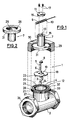
- a current monitor 1 shown in FIG. 1 essentially has a line piece 2 to be flowed through by the medium to be monitored and provided with a lateral line connection piece 27, an actuating element 5, a cap-shaped housing 7, and a protective contact 10 surrounding it as a reed contact trained switch 9 and a lid 11.
- the pipe section 2 has an opening 4 in the pipe socket 27, which is surrounded by a flange 12 provided with an external screw thread 28.
- connection between the one cylindrical housing 7 and the line piece 2 takes place via a union nut 29, which rotatably comes into contact with an inwardly extending shoulder 30 on the back of a flange 31 arranged at the front end of the housing 7 and can be screwed onto the screw thread 28 .
- the end face 21 of the flange 12 has an annular groove 32 with an inserted sealing ring 33.
- the end face of the flange 31 of the housing 7 has a shoulder 25 which is to be placed on the upper side of the support plate 18 and has a radial groove 26 for the nose 22 of the support plate 18, the support plate 18 with nose being in the assembled state 22 is positively received between the end face 21 of the flange 12 with an associated groove 23 and the shoulder 25 formed on the inside of the flange 31 with an associated groove 26.
- the groove-shaped recess 13 provided at its upper end defines the position of the protective sheath 10 surrounding the switch 9 with respect to the effective range of the permanent magnet 8.
- a flow monitor is created, which has good access for maintenance and cleaning of the parts prone to contamination, as well as an automatic fixation of the inflow part or its inflow surface in the flow path of the medium and at the same time an alignment of the switch in the effective range of the permanent magnet during the Installation of the flow switch allowed.
- the switch can be installed without problems.
Landscapes
- Physics & Mathematics (AREA)
- General Physics & Mathematics (AREA)
- Measuring Volume Flow (AREA)
- Indicating Or Recording The Presence, Absence, Or Direction Of Movement (AREA)
- Feeding And Controlling Fuel (AREA)
Claims (11)
- Dispositif de surveillance de l'écoulement (1) monté sur un tronçon de tuyauterie (2) parcouru par le fluide à surveiller, comportant un élément de commande (5), qui est monté sur un support avec possibilité de déplacement à l'encontre de la force d'un ressort (6) de manière telle, qu'une partie immergée (3) pénètre par une ouverture (4) de la paroi du tronçon de tuyauterie (2) jusque dans le trajet d'écoulement du fluide et que l'autre extrémité de l'élément de commande (5) fait saillie dans un boîtier (7) placé au-dessus de l'ouverture (4) du tronçon de tuyauterie (2) et relié de manière démontable à celui-ci, et porte un aimant permanent (8) conçu de manière à commander, lors d'une déviation de l'élément de commande (5), un commutateur (9) d'un circuit se présentant sous la formé d'un contact de Reed, qui est entouré d'une enveloppe protectrice (10) et est logé dans une ouverture du boîtier (7), caractérisé en ce que le support est réalisé sous la forme d'une plaque-support (18) qui s'engage à des fins de positionnement angulaire, par un ergot (22) dans une rainure (23) aménagée au niveau de l'ouverture (4) dans la paroi du tronçon de tuyauterie (2), et par ce même ergot ou par un ergot supplémentaire, dans une rainure (26) aménagée dans le boîtier (7), la plaque-support (18) étant démontable, l'enveloppe protectrice (10) du commutateur (9) et la plaque-support (18) étant maintenus fixes en rotation.
- Dispositif de surveillance de l'écoulement selon la revendication 1, caractérisé en ce que la plaque-support (18) repose sur un épaulement (20) de la surface frontale (21) de l'ouverture (4) dans la paroi du tronçon de tuyauterie (2), venant en contact avec le bord inférieur du boîtier (7).
- Dispositif de surveillance de l'écoulement selon la revendication 2, caractérisé en ce que la plaque-support (18) est montée essentiellement par conjugaison de formes entre l'épaulement (20) et un épaulement (25) aménagé sur la face intérieure du bord inférieur du boîtier (7).
- Dispositif de surveillance de l'écoulement selon l'une des revendications 1 à 3, caractérisé en ce que la plaque-support (18) est serrée entre une bride (31) du boitier (7) et une bride (12) de l'ouverture (4), dans la paroi du tronçon de tuyauterie (2).
- Dispositif de surveillance de l'écoulement selon la revendication 4, caractérisé en ce que la bride (12) associée au tronçon de tuyauterie (2) comporte une gorge annulaire (32) munie d'un joint d'étanchéité (33).
- Dispositif de surveillance de l'écoulement selon l'une des revendications 1 à 5, caractérisé en ce que la paroi (15) du boîtier est réalisée essentiellement en forme de coiffe cylindrique, qui présente à son extrémité extérieure une ouverture (13, 16) pour le montage de l'enveloppe protectrice (10) du commutateur (9) et en ce que l'enveloppe protectrice (10) et le commutateur (9) sont tenus sur le boîtier (7) par un couvercle (11) qui peut être fixé en maintenant libre l'ouverture (13, 16).
- Dispositif de surveillance de l'écoulement selon la revendication 6, caractérisé en ce que l'ouverture (13, 16) recevant l'enveloppe protectrice (10) du commutateur (9) est formée par un évidement (13) dans l'extrémité du boîtier (7) et par un évidement (16) dans le couvercle (11).
- Dispositif de surveillance de l'écoulement selon la revendication 6, caractérisé en ce que l'enveloppe protectrice (10) du commutateur (9) est aplatie dans la région de sa paroi extérieure venant en contact avec une surface maintenue plane du couvercle (11).
- Dispositif de surveillance de l'écoulement selon l'une des revendications 1 à 8, caractérisé en ce que l'immobilisation en rotation de l'enveloppe protectrice (10) du commutateur (9) est réalisée sous forme de système rainure-clavette.
- Dispositif de surveillance de l'écoulement selon l'une des revendications 6 à 8, caractérisé en ce que le couvercle (11) est monté au moyen d'un assemblage vissé (17) sur le boîtier (7) avec serrage sur une grande surface de l'enveloppe protectrice (10) du commutateur (9) dans l'ouverture (13, 16).
- Dispositif de surveillance de l'écoulement selon l'une des revendications précédentes, caractérisé en ce que le boîtier (7) au moins est en matériau non magnétisable, tel que du laiton, de la matière plastique ou analogue.
Priority Applications (1)
| Application Number | Priority Date | Filing Date | Title |
|---|---|---|---|
| AT87117642T ATE71454T1 (de) | 1986-12-09 | 1987-11-28 | Stroemungswaechter. |
Applications Claiming Priority (2)
| Application Number | Priority Date | Filing Date | Title |
|---|---|---|---|
| DE8632832U | 1986-12-09 | ||
| DE8632832U DE8632832U1 (de) | 1986-12-09 | 1986-12-09 | Strömungswächter |
Publications (2)
| Publication Number | Publication Date |
|---|---|
| EP0270960A1 EP0270960A1 (fr) | 1988-06-15 |
| EP0270960B1 true EP0270960B1 (fr) | 1992-01-08 |
Family
ID=6800944
Family Applications (1)
| Application Number | Title | Priority Date | Filing Date |
|---|---|---|---|
| EP87117642A Expired - Lifetime EP0270960B1 (fr) | 1986-12-09 | 1987-11-28 | Appareil de surveillance d'écoulement |
Country Status (6)
| Country | Link |
|---|---|
| US (1) | US4827092A (fr) |
| EP (1) | EP0270960B1 (fr) |
| AT (1) | ATE71454T1 (fr) |
| CA (1) | CA1309875C (fr) |
| DE (2) | DE8632832U1 (fr) |
| ES (1) | ES2029821T3 (fr) |
Families Citing this family (11)
| Publication number | Priority date | Publication date | Assignee | Title |
|---|---|---|---|---|
| US5021619A (en) * | 1990-04-02 | 1991-06-04 | Harwil Corporation | Flow responsive switch apparatus |
| US5091612A (en) * | 1990-10-31 | 1992-02-25 | Johnson Service Company | Magnetically actuated proximity flow switch |
| US5126097A (en) * | 1991-06-07 | 1992-06-30 | Yu Feng Enterprise Co., Ltd. | Fluid flow sensing and switching device |
| US5183983A (en) * | 1992-03-20 | 1993-02-02 | Dwyer Instruments, Inc. | Flow switch assembly for fluid flow monitoring |
| US6032540A (en) * | 1998-03-27 | 2000-03-07 | Agrilcultural Products Inc. | In-line, field adjustable irrigation flow indicator for high, normal and low flow rates |
| US6563064B2 (en) | 2000-12-21 | 2003-05-13 | Itt Manufacturing Enterprises, Inc. | Fluid flow switch sensing device having a test button |
| US6548775B1 (en) | 2002-06-21 | 2003-04-15 | Breed Automotive Technology, Inc. | Paddle flow monitoring device |
| US20050028609A1 (en) * | 2003-07-17 | 2005-02-10 | Langemann Peter J. | Flow-monitoring method and device |
| US7105756B1 (en) * | 2005-09-21 | 2006-09-12 | Plastic Magen, Lp | Flowswitch having reduced number of parts |
| US7389684B2 (en) * | 2005-11-03 | 2008-06-24 | Roy Jude B | Gas lift flow surveillance device |
| CN101405587B (zh) * | 2006-03-29 | 2010-11-17 | 株式会社Jms | 压力检测装置 |
Family Cites Families (9)
| Publication number | Priority date | Publication date | Assignee | Title |
|---|---|---|---|---|
| US2600309A (en) * | 1950-02-14 | 1952-06-10 | Revere Corp America | Flow-responsive electrical switch means |
| US2943486A (en) * | 1957-02-18 | 1960-07-05 | Richard E Osgood | High response flow-meter |
| US3368045A (en) * | 1964-11-30 | 1968-02-06 | Acme Machine Works Inc | Flow indicator utilizing permanent magnets for switch actuation |
| US4074097A (en) * | 1976-10-18 | 1978-02-14 | Hutchinson Harold D | Fluid responsive sealed pivot arm means |
| DE2744901C2 (de) * | 1977-10-06 | 1985-06-13 | Turbo-Werk Messtechnik GmbH, 5000 Köln | Wächter für den Durchfluß oder Füllstand von Medien |
| US4282413A (en) * | 1979-07-02 | 1981-08-04 | Grunau Company, Inc. | Liquid flow indicator |
| DE2926811A1 (de) * | 1979-07-03 | 1981-01-22 | Malmedie & Co Maschf | Durchflussmesseinrichtung |
| DE2946826C2 (de) * | 1979-11-20 | 1984-01-19 | Interflux AG, 8700 Küsnacht, Zürich | Durchflußwächter für flüssige oder gasförmige Medien |
| DE3317923A1 (de) * | 1982-05-19 | 1983-11-24 | Gerhard Walter Prof. Dr.-Ing. 5630 Remscheid Seulen | Durchflussschalter |
-
1986
- 1986-12-09 DE DE8632832U patent/DE8632832U1/de not_active Expired
-
1987
- 1987-11-28 EP EP87117642A patent/EP0270960B1/fr not_active Expired - Lifetime
- 1987-11-28 AT AT87117642T patent/ATE71454T1/de not_active IP Right Cessation
- 1987-11-28 DE DE8787117642T patent/DE3775903D1/de not_active Expired - Lifetime
- 1987-11-28 ES ES198787117642T patent/ES2029821T3/es not_active Expired - Lifetime
- 1987-12-09 US US07/132,884 patent/US4827092A/en not_active Expired - Lifetime
- 1987-12-09 CA CA000553888A patent/CA1309875C/fr not_active Expired - Lifetime
Also Published As
| Publication number | Publication date |
|---|---|
| ES2029821T3 (es) | 1992-10-01 |
| EP0270960A1 (fr) | 1988-06-15 |
| ATE71454T1 (de) | 1992-01-15 |
| DE3775903D1 (de) | 1992-02-20 |
| DE8632832U1 (de) | 1987-03-05 |
| US4827092A (en) | 1989-05-02 |
| CA1309875C (fr) | 1992-11-10 |
Similar Documents
| Publication | Publication Date | Title |
|---|---|---|
| DE68911842T2 (de) | Filtersystem. | |
| DE19781179B4 (de) | Nichtmetallisches, austauschbares Filter | |
| DE4240512C2 (de) | Durchflußschalter | |
| DE102013101120A1 (de) | Kabelfixierung | |
| DE3813091C2 (de) | Luftströmungsschalter für Luftleitungen | |
| DE4017328C1 (fr) | ||
| EP0559938B1 (fr) | Débitmètre à ultrasons pour des liquides | |
| EP0270960A1 (fr) | Appareil de surveillance d'écoulement | |
| DE2417064C3 (de) | Strömungsschalter | |
| EP0139943B1 (fr) | Dispositif d'étranglement | |
| DE102008055518A1 (de) | Verbindungsstück | |
| EP0570667B1 (fr) | Connection de serrage en plastique | |
| DE69813857T2 (de) | Werkzeug für spanabhebende bearbeitung | |
| EP1193433B1 (fr) | Soupape électromagnétique | |
| DE3438077A1 (de) | Sperrventil fuer fluessigkeiten | |
| DE2004205A1 (de) | Hochdruckfiltervorrichtung | |
| EP4347961B1 (fr) | Dispositif pour modifier un chemin d'écoulement d'un liquide d'une douche sanitaire | |
| EP0604835A1 (fr) | Robinet à papillon | |
| DE202004014184U1 (de) | Vorrichtung zum Reinigen eines Meßseils bei einem Seillängengeber | |
| DE3800374C2 (fr) | ||
| EP0937490B1 (fr) | Dispositif de filtration modulaire | |
| DE3527357C2 (fr) | ||
| DE2800948C2 (de) | Gleitringdichtung | |
| DE19715780A1 (de) | Vorrichtung zur optischen Erfassung von Störlichtbogen in Schaltgeräten und -anlagen | |
| WO2021074067A1 (fr) | Insert de filtre pour la séparation de liquides, en particulier d'un aérosol |
Legal Events
| Date | Code | Title | Description |
|---|---|---|---|
| PUAI | Public reference made under article 153(3) epc to a published international application that has entered the european phase |
Free format text: ORIGINAL CODE: 0009012 |
|
| AK | Designated contracting states |
Kind code of ref document: A1 Designated state(s): AT BE CH DE ES FR GB IT LI NL SE |
|
| 17P | Request for examination filed |
Effective date: 19881011 |
|
| 17Q | First examination report despatched |
Effective date: 19891116 |
|
| GRAA | (expected) grant |
Free format text: ORIGINAL CODE: 0009210 |
|
| AK | Designated contracting states |
Kind code of ref document: B1 Designated state(s): AT BE CH DE ES FR GB IT LI NL SE |
|
| REF | Corresponds to: |
Ref document number: 71454 Country of ref document: AT Date of ref document: 19920115 Kind code of ref document: T |
|
| REF | Corresponds to: |
Ref document number: 3775903 Country of ref document: DE Date of ref document: 19920220 |
|
| ITF | It: translation for a ep patent filed | ||
| GBT | Gb: translation of ep patent filed (gb section 77(6)(a)/1977) | ||
| ET | Fr: translation filed | ||
| REG | Reference to a national code |
Ref country code: ES Ref legal event code: FG2A Ref document number: 2029821 Country of ref document: ES Kind code of ref document: T3 |
|
| PLBE | No opposition filed within time limit |
Free format text: ORIGINAL CODE: 0009261 |
|
| STAA | Information on the status of an ep patent application or granted ep patent |
Free format text: STATUS: NO OPPOSITION FILED WITHIN TIME LIMIT |
|
| 26N | No opposition filed | ||
| EAL | Se: european patent in force in sweden |
Ref document number: 87117642.6 |
|
| REG | Reference to a national code |
Ref country code: GB Ref legal event code: IF02 |
|
| PGFP | Annual fee paid to national office [announced via postgrant information from national office to epo] |
Ref country code: GB Payment date: 20021104 Year of fee payment: 16 |
|
| PGFP | Annual fee paid to national office [announced via postgrant information from national office to epo] |
Ref country code: NL Payment date: 20021118 Year of fee payment: 16 Ref country code: FR Payment date: 20021118 Year of fee payment: 16 |
|
| PGFP | Annual fee paid to national office [announced via postgrant information from national office to epo] |
Ref country code: AT Payment date: 20021119 Year of fee payment: 16 |
|
| PGFP | Annual fee paid to national office [announced via postgrant information from national office to epo] |
Ref country code: SE Payment date: 20021122 Year of fee payment: 16 Ref country code: CH Payment date: 20021122 Year of fee payment: 16 Ref country code: BE Payment date: 20021122 Year of fee payment: 16 |
|
| PGFP | Annual fee paid to national office [announced via postgrant information from national office to epo] |
Ref country code: ES Payment date: 20021126 Year of fee payment: 16 |
|
| PG25 | Lapsed in a contracting state [announced via postgrant information from national office to epo] |
Ref country code: GB Free format text: LAPSE BECAUSE OF NON-PAYMENT OF DUE FEES Effective date: 20031128 Ref country code: AT Free format text: LAPSE BECAUSE OF NON-PAYMENT OF DUE FEES Effective date: 20031128 |
|
| PG25 | Lapsed in a contracting state [announced via postgrant information from national office to epo] |
Ref country code: SE Free format text: LAPSE BECAUSE OF NON-PAYMENT OF DUE FEES Effective date: 20031129 Ref country code: ES Free format text: LAPSE BECAUSE OF NON-PAYMENT OF DUE FEES Effective date: 20031129 |
|
| PG25 | Lapsed in a contracting state [announced via postgrant information from national office to epo] |
Ref country code: LI Free format text: LAPSE BECAUSE OF NON-PAYMENT OF DUE FEES Effective date: 20031130 Ref country code: CH Free format text: LAPSE BECAUSE OF NON-PAYMENT OF DUE FEES Effective date: 20031130 Ref country code: BE Free format text: LAPSE BECAUSE OF NON-PAYMENT OF DUE FEES Effective date: 20031130 |
|
| BERE | Be: lapsed |
Owner name: *KOBOLD KLAUS Effective date: 20031130 |
|
| PG25 | Lapsed in a contracting state [announced via postgrant information from national office to epo] |
Ref country code: NL Free format text: LAPSE BECAUSE OF NON-PAYMENT OF DUE FEES Effective date: 20040601 |
|
| EUG | Se: european patent has lapsed | ||
| REG | Reference to a national code |
Ref country code: CH Ref legal event code: PL |
|
| GBPC | Gb: european patent ceased through non-payment of renewal fee |
Effective date: 20031128 |
|
| PG25 | Lapsed in a contracting state [announced via postgrant information from national office to epo] |
Ref country code: FR Free format text: LAPSE BECAUSE OF NON-PAYMENT OF DUE FEES Effective date: 20040730 |
|
| NLV4 | Nl: lapsed or anulled due to non-payment of the annual fee |
Effective date: 20040601 |
|
| REG | Reference to a national code |
Ref country code: FR Ref legal event code: ST |
|
| REG | Reference to a national code |
Ref country code: ES Ref legal event code: FD2A Effective date: 20031129 |
|
| PG25 | Lapsed in a contracting state [announced via postgrant information from national office to epo] |
Ref country code: IT Free format text: LAPSE BECAUSE OF NON-PAYMENT OF DUE FEES;WARNING: LAPSES OF ITALIAN PATENTS WITH EFFECTIVE DATE BEFORE 2007 MAY HAVE OCCURRED AT ANY TIME BEFORE 2007. THE CORRECT EFFECTIVE DATE MAY BE DIFFERENT FROM THE ONE RECORDED. Effective date: 20051128 |
|
| PGFP | Annual fee paid to national office [announced via postgrant information from national office to epo] |
Ref country code: DE Payment date: 20070124 Year of fee payment: 20 |