EP0271263A2 - Verfahren und Vorrichtung zum Auflegen einer Folie auf eine Oberfläche - Google Patents
Verfahren und Vorrichtung zum Auflegen einer Folie auf eine Oberfläche Download PDFInfo
- Publication number
- EP0271263A2 EP0271263A2 EP87310462A EP87310462A EP0271263A2 EP 0271263 A2 EP0271263 A2 EP 0271263A2 EP 87310462 A EP87310462 A EP 87310462A EP 87310462 A EP87310462 A EP 87310462A EP 0271263 A2 EP0271263 A2 EP 0271263A2
- Authority
- EP
- European Patent Office
- Prior art keywords
- sheet
- diaphragm
- transfer tool
- tool
- transfer
- Prior art date
- Legal status (The legal status is an assumption and is not a legal conclusion. Google has not performed a legal analysis and makes no representation as to the accuracy of the status listed.)
- Withdrawn
Links
Images


Classifications
-
- B—PERFORMING OPERATIONS; TRANSPORTING
- B29—WORKING OF PLASTICS; WORKING OF SUBSTANCES IN A PLASTIC STATE IN GENERAL
- B29C—SHAPING OR JOINING OF PLASTICS; SHAPING OF MATERIAL IN A PLASTIC STATE, NOT OTHERWISE PROVIDED FOR; AFTER-TREATMENT OF THE SHAPED PRODUCTS, e.g. REPAIRING
- B29C70/00—Shaping composites, i.e. plastics material comprising reinforcements, fillers or preformed parts, e.g. inserts
- B29C70/04—Shaping composites, i.e. plastics material comprising reinforcements, fillers or preformed parts, e.g. inserts comprising reinforcements only, e.g. self-reinforcing plastics
- B29C70/28—Shaping operations therefor
- B29C70/54—Component parts, details or accessories; Auxiliary operations, e.g. feeding or storage of prepregs or SMC after impregnation or during ageing
- B29C70/541—Positioning reinforcements in a mould, e.g. using clamping means for the reinforcement
-
- B—PERFORMING OPERATIONS; TRANSPORTING
- B29—WORKING OF PLASTICS; WORKING OF SUBSTANCES IN A PLASTIC STATE IN GENERAL
- B29C—SHAPING OR JOINING OF PLASTICS; SHAPING OF MATERIAL IN A PLASTIC STATE, NOT OTHERWISE PROVIDED FOR; AFTER-TREATMENT OF THE SHAPED PRODUCTS, e.g. REPAIRING
- B29C70/00—Shaping composites, i.e. plastics material comprising reinforcements, fillers or preformed parts, e.g. inserts
- B29C70/04—Shaping composites, i.e. plastics material comprising reinforcements, fillers or preformed parts, e.g. inserts comprising reinforcements only, e.g. self-reinforcing plastics
- B29C70/28—Shaping operations therefor
- B29C70/30—Shaping by lay-up, i.e. applying fibres, tape or broadsheet on a mould, former or core; Shaping by spray-up, i.e. spraying of fibres on a mould, former or core
-
- B—PERFORMING OPERATIONS; TRANSPORTING
- B29—WORKING OF PLASTICS; WORKING OF SUBSTANCES IN A PLASTIC STATE IN GENERAL
- B29L—INDEXING SCHEME ASSOCIATED WITH SUBCLASS B29C, RELATING TO PARTICULAR ARTICLES
- B29L2031/00—Other particular articles
- B29L2031/08—Blades for rotors, stators, fans, turbines or the like, e.g. screw propellers
- B29L2031/082—Blades, e.g. for helicopters
Definitions
- This invention relates to a method and apparatus for laying a sheet of material on a surface, and is particularly concerned with the laying of such sheet material having a naturally sticky or tacky texture.
- One such material consists of a pre-impregnated fibre-reinforced material by which we mean a material comprising a layer of woven, unidirectional or random fibres impregnated with a thermo-setting resin.
- a pre-impregnated fibre-reinforced material by which we mean a material comprising a layer of woven, unidirectional or random fibres impregnated with a thermo-setting resin.
- Such materials are now widely used due to their high strength to weight ratio and the relative ease by which complex shapes can be made using appropriate mould or forming tools, and find particular application in the aircraft industry for example in the manufacture of helicopter rotor blades.
- sheet is intended to include a sheet cut from a roll of material and a sheet made up of a plurality of adjacently laid narrow tapes.
- the invention provides a method for laying a sheet of material on to a surface comprising the steps of applying pressure by way of an inflatable flexible diaphragm to force the sheet of material on to the surface, and thereafter adjusting the position of the diaphragm so that the surface of the diaphragm assumes a varying curved convex shape whereby said diaphragm is peeled gradually from the surface of the sheet of material inwardly from an edge region.
- the varying curved convex surface may be formed by slowly withdrawing the inflated diaphragm from said surface and the sheet of material thereon.
- the invention provides a method for laying a sheet of pre-impregnated fibre-reinforced material on to a surface, comprising the steps of locating a transfer tool carrying the sheet of material so that said sheet is in contact with the said surface, inflating a flexible diaphragm between juxtaposed surfaces of the transfer tool and the sheet of material whereby a substantially uniform pressure is applied to force the sheet into contact with the surface, withdrawing the transfer tool from the surface to cause the diaphragm to stretch under the influence of the inflation pressure so as to take a varying curved convex shape as the transfer tool is withdrawn from the surface whereby the diaphragm is peeled gradually from the surface of the sheet of material inwardly from its edge region, and removing the transfer tool.
- the above method can be preceded by cutting the sheet of pre-impregnated fibre-reinforced material to a desired profile on a generally flat cutting table, locating the transfer tool in proximity with the sheet of material on the cutting table, inflating the diaphragm to apply a uniform pressure over the surface of the sheet of material so that the sheet of material becomes attached to the surface of the diaphragm on the transfer tool, releasing the inflating pressure, and withdrawing the transfer tool and attached sheet of material from the cutting table.
- the aforementioned method may be preceded by forming the sheet of material to a desired profile using a plurality of adjacently laid narrow tapes on a generally flat surface, locating the transfer tool in proximity with the sheet of material, inflating the diaphragm to apply a uniform pressure over the surface of the sheet of material so that the sheet of material becomes attached to the surface of the diaphragm on the transfer tool, releasing the inflating pressure, and withdrawing the transfer tool and attached sheet of material from the surface.
- a vacuum may be applied following deflation of the diaphragm whereby the diaphragm and attached sheet of material are drawn into conformity with the shape of the surface of the transfer tool.
- the aforementioned method may be preceded by forming the sheet of material to a desired profile using a plurality of adjacent narrow tapes laid directly on the generally flat surface of a flexible diaphragm secured around the periphery of the transfer tool.
- the invention provides apparatus for laying a sheet of material on to a surface comprising a transfer tool for transferring a layer of said material between various stages of a manufacturing process, said transfer tool having a transfer surface, a flexible diaphragm fluid tightly attached across said surface and means for introducing pressurised fluid so that during certain phases of operation the diaphragm is stretched so as to form a curved convex protrusion.
- the transfer surface may be shaped so as to conform during certain phases of operation with the shape of the surface of a forming tool into which said layer of material is to be transferred.
- Means may also be provided for establishing a vacuum inside the diaphragm during certain phases of operation to draw the diaphragm into contact with the transfer surface.
- the invention provides apparatus for the manufacture of a helicopter rotor blade from pre-impregnated fibre-reinforced material including a cutting table in which sheets of said material to be used in the manufacture of the blade are cut to a desired profile, a mould tool in which said sheets are laid and subsequently cured by the application of heat and pressure, and a transfer tool for transferring sheets from the cutting table to a desired location in the mould tool, said transfer tool having a transfer surface covered by a flexible diaphragm on which the sheet is transferred and means for inflating the diaphragm after location of the sheet in the mould tool, whereby as the transfer tool is withdrawn from the mould tool the diaphragm automatically assumes a varying curved convex shape so that the diaphragm is peeled gradually from the surface of the sheet of material inwardly from an outer edge region.
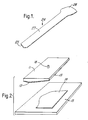
- a helicopter main sustaining rotor blade 24 constructed of pre-impregnated fibre-reinforced material includes a root end 25 adapted for attachment to a rotor hub (not shown), a central parallel portion 27 having an aerofoil cross sectional shape and a tip portion 28 having an intricate plan form profile.
- a transfer tool 11 has a surface 12 shaped to conform to the shape of the surface of a forming tool (not shown) with which it is to be used.
- a flexible diaphragm 13 is fluid tightly attached around the periphery of transfer tool 11 and a pipe 18 protruding from the rear surface of tool 11 is provided for selectively connecting a supply of pressurised fluid or a source of vacuum to the interior of the diaphragm 13.
- the transfer tool 11 is used in an automated manufacturing process for manufacturing the helicopter main rotor blade 24 illustrated in Figure 1.
- the tool 11 is used in the construction of the intricately shaped tip portion 28 of the blade by transferring sheets of pre-impregnated fibre-reinforced material cut to a desired profile on a cutting table to a mould tool in which the rotor blade is eventually cured by the application of heat and pressure.
- a sequence of steps involved in a method according to one embodiment of the invention will now be described with reference to Figures 3 to 7 inclusive.
- a sheet 14 of pre-impregnated fibre-reinforced material is cut from a roll of material on a generally flat cutting table 15 to a predetermined profile shape required in the tip area 28 of the helicopter rotor blade 24 ( Figure 1).
- the transfer tool 11 is located with the flexible diaphragm 13 lowermost and is lowered until the diaphragm 13 just contacts the upper surface of sheet 14.
- Air pressure is introduced through pipe 18 to inflate the diaphragm 13 ( Figure 4) so that a uniform pressure is applied over the entire surface of the sheet 14 which due to the aforementioned natural tackiness of the material, ensures that the sheet 14 adheres to the surface of the diaphragm 13.
- the air pressure is released and a source of vacuum applied through pipe 18 to draw the diaphragm 13 and attached sheet 14 into conformity with the shape of the lower surface 12 of transfer tool 11, as illustrated in Figure 5.
- Transfer tool 11 is then moved to a mould tool 16 having an upper profiled surface 17 shaped to conform to the external shape of one half of the rotor blade 24.
- the transfer tool 11 is lowered until the sheet 14 is correctly positioned in the tip area 28 of the blade and in contact with surface 17 as shown in Figure 6.
- Air pressure is again introduced through pipe 18 to inflate diaphragm 13 and provide a substantially uniform pressure forcing the sheet 14 into contact with surface 17 of mould tool 16.
- Transfer tool 11 is then slowly withdrawn from tool 16 as shown in Figure 7 which causes stretching of diaphragm 13 under the influence of the inflation pressure so that the surface of the diaghragm 13 assumes a convex surface that is presented towards tool 16, the curvature varying as the separation distance increases.
- This causes the surface of the diaphragm 13 to be peeled gradually away from the surface of sheet 14 inwardly from its edge region so as to release a gradually increasing area of the upper surface of sheet 14.
- the adhesion between the whole of the area of the lower surface of sheet 14 and the surface of the tool 16 is greater than that between the upper surface of sheet 14 and the small area of the diaphragm 13 that is being continuously peeled away which ensures that the sheet 14 is retained in the mould tool 16 whilst the transfer tool 11 is withdrawn.
- lay-up procedure is repeated in a second identical mould tool 16 to produce the other half of the rotor blade 24, whereafter the two are joined and the lay-up cured by the application of heat and pressure to form the complete rotor blade 24.
- the desired thickness of material can be built up on the surface of the diaphragm 13 on the transfer tool 11 itself either automatically as described or by hand lay-up of individual sheets 14 previously cut to a desired profile. In such an embodiment it is desirable that the multi-layer lay-up is de-bulked prior to being transferred to the surface 17 of mould tool 16.
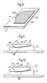
- the shaped sheet of pre-impregnated fibre-reinforced material 19 is made up of a plurality of adjacently laid narrow tapes 19 a .
- the tapes 19 a are laid by a tape laying machine directly on the surface of a flexible diaphragm 20 secured around the periphery of a flat surface 21 of a transfer tool 22 as shown in Figure 8.
- Transfer tool 22 is then inverted as shown in Figure 9, located above the mould tool 16 and the diaphragm 20 is inflated through pipe 23 to provide a substantially uniform pressure forcing the sheet 19 comprising tapes 19 a into contact with surface 17 of mould tool 16.
- the transfer tool 22 is then slowly withdrawn from mould tool 16 as shown in Figure 10 which causes stretching of the diaphragm 20 so that it is peeled gradually away from the surface of the sheet 19 inwardly from its edge region.
- the tapes 19 a could be laid on a flat surface similar to the cutting table 15 of the embodiment of Figures 2 to 7, and transferred to the mould tool 16 using either the transfer tool 11 of Figures 2 to 7 inclusive or the transfer tool 22 of the embodiment of Figures 8 to 10 inclusive. Both alternatives represent a simpler operation than the current technique of laying tape directly on to the concave surface such as surface 17 of mould tool 16.
- this invention overcomes the aforementioned problem by ensuring sufficient transfer of a sheet of tacky material from a transfer tool on to a curved surface of a mould tool and therefore makes possible automated techniques in the manufacture of composite components to improve consistency of the products and minimise manufacturing costs.
- the invention has been described and illustrated with particular reference to the laying of pre-impregnated fibre-reinforced materials and to the use of such materials in the manufacture of a helicopter blade, however, the invention can of course be used with other materials and in the manufacture of other components such as wing sections and body panels for fixed wing aircraft.
Landscapes
- Chemical & Material Sciences (AREA)
- Engineering & Computer Science (AREA)
- Composite Materials (AREA)
- Mechanical Engineering (AREA)
- Moulding By Coating Moulds (AREA)
- Casting Or Compression Moulding Of Plastics Or The Like (AREA)
- Lining Or Joining Of Plastics Or The Like (AREA)
Applications Claiming Priority (2)
| Application Number | Priority Date | Filing Date | Title |
|---|---|---|---|
| GB8629267 | 1986-12-08 | ||
| GB868629267A GB8629267D0 (en) | 1986-12-08 | 1986-12-08 | Laying pre-impregnated fibre reinforced material on surface |
Publications (2)
| Publication Number | Publication Date |
|---|---|
| EP0271263A2 true EP0271263A2 (de) | 1988-06-15 |
| EP0271263A3 EP0271263A3 (de) | 1990-03-14 |
Family
ID=10608626
Family Applications (1)
| Application Number | Title | Priority Date | Filing Date |
|---|---|---|---|
| EP87310462A Withdrawn EP0271263A3 (de) | 1986-12-08 | 1987-11-26 | Verfahren und Vorrichtung zum Auflegen einer Folie auf eine Oberfläche |
Country Status (3)
| Country | Link |
|---|---|
| US (1) | US4875962A (de) |
| EP (1) | EP0271263A3 (de) |
| GB (1) | GB8629267D0 (de) |
Cited By (20)
| Publication number | Priority date | Publication date | Assignee | Title |
|---|---|---|---|---|
| WO1991013747A1 (es) * | 1990-03-15 | 1991-09-19 | Construcciones Aeronauticas, S.A. | Maquina para el transporte y posicionado de precision de piezas de tejido, cintas y similares |
| EP0577505A1 (de) * | 1992-07-02 | 1994-01-05 | Societe Nationale D'etude Et De Construction De Moteurs D'aviation "Snecma" | Einhüllanlage zur Herstellung von mehrlagigen Strukturen aus Kompositmaterialien |
| EP0588363A1 (de) * | 1992-09-18 | 1994-03-23 | IVECO FIAT S.p.A. | Kunststoffplattenhaltevorrichtung zum Beladen von einer Form |
| US6723272B2 (en) | 2000-06-10 | 2004-04-20 | Westland Helicopters Limited | Moulding process |
| WO2007039085A1 (en) * | 2005-09-20 | 2007-04-12 | Airbus Deutschland Gmbh | Method and device for placing thin material layers onto a relief mould |
| EP2338668A1 (de) * | 2009-12-22 | 2011-06-29 | Lm Glasfiber A/S | Verfahren zur Herstellung einer Verbundschalenstruktur |
| EP2383106A1 (de) * | 2010-04-27 | 2011-11-02 | The Boeing Company | Verfahren und Vorrichtung zur Bildung und Ablage von Verbundlagenwerkstoffen mit komplexen Geometrien |
| CN102555229A (zh) * | 2010-11-12 | 2012-07-11 | 波音公司 | 使用可变形载体膜在弯曲工具上铺设预浸层板的方法 |
| US8333864B2 (en) | 2008-09-30 | 2012-12-18 | The Boeing Company | Compaction of prepreg plies on composite laminate structures |
| US8505361B2 (en) | 2006-12-22 | 2013-08-13 | The Boeing Company | Leak detection in vacuum bags |
| US8568551B2 (en) | 2007-05-22 | 2013-10-29 | The Boeing Company | Pre-patterned layup kit and method of manufacture |
| EP2703150A1 (de) * | 2012-09-04 | 2014-03-05 | Robert Bürkle GmbH | Verfahren und Vorrichtung zum Einlegen von Gelegen aus Rovings in eine Presse |
| US8707766B2 (en) | 2010-04-21 | 2014-04-29 | The Boeing Company | Leak detection in vacuum bags |
| US8752293B2 (en) | 2007-12-07 | 2014-06-17 | The Boeing Company | Method of fabricating structures using composite modules and structures made thereby |
| US8916010B2 (en) | 2007-12-07 | 2014-12-23 | The Boeing Company | Composite manufacturing method |
| US9387657B2 (en) | 2010-11-12 | 2016-07-12 | The Boeing Company | Method of fabricating a curved composite structure using composite prepreg tape |
| EP2937207A4 (de) * | 2012-11-23 | 2016-09-14 | Ind Delta Vigo S L | System zur handhabung von porösen geweben |
| US9586344B2 (en) | 2014-09-03 | 2017-03-07 | The Boeing Company | Method and system of forming a releasable support and method of pre-cure removal of a composite laminate |
| US9701067B2 (en) | 2010-11-12 | 2017-07-11 | The Boeing Company | Method of laying up prepreg plies on contoured tools using a deformable carrier film |
| US9770871B2 (en) | 2007-05-22 | 2017-09-26 | The Boeing Company | Method and apparatus for layup placement |
Families Citing this family (13)
| Publication number | Priority date | Publication date | Assignee | Title |
|---|---|---|---|---|
| JP2923126B2 (ja) * | 1991-10-28 | 1999-07-26 | コーニング インコーポレイテッド | オフセット熱剥離デカルコマニア転写装置および方法 |
| US5648109A (en) * | 1995-05-03 | 1997-07-15 | Massachusetts Institute Of Technology | Apparatus for diaphragm forming |
| US20110198024A1 (en) * | 2007-04-05 | 2011-08-18 | Avery Dennison Corporation | Systems and Processes for Applying Heat Transfer Labels |
| WO2011094117A2 (en) | 2010-01-28 | 2011-08-04 | Avery Dennison Corporation | Label applicator belt system |
| US8997642B2 (en) * | 2011-08-08 | 2015-04-07 | The Boeing Company | Method for transporting, placing and compacting composite stiffeners |
| US9931807B2 (en) | 2011-08-08 | 2018-04-03 | The Boeing Company | Flexible compactor with reinforcing spine |
| WO2014107241A1 (en) * | 2013-01-07 | 2014-07-10 | The Boeing Company | Method of fabricating a curved composite structure using composite prepreg tape |
| US9272767B2 (en) | 2013-04-19 | 2016-03-01 | The Boeing Company | Compacting uncured composite members on contoured mandrel surfaces |
| US9370922B1 (en) * | 2014-03-18 | 2016-06-21 | The Boeing Company | Systems and methods for stretch-forming multi-thickness composite skins |
| US9873230B1 (en) | 2014-08-19 | 2018-01-23 | The Boeing Company | Mobile system for automated layup and compaction of composite laminates |
| US11951695B2 (en) * | 2017-02-02 | 2024-04-09 | Toray Industries, Inc. | Method for producing fiber-reinforced plastic |
| GB2566752B (en) * | 2017-09-26 | 2020-09-16 | Univ Cranfield | Method of manufacturing a moulded article |
| CN116161472B (zh) * | 2022-12-30 | 2025-10-21 | 南京航空航天大学无锡研究院 | 大宽度编织带展带装置及方法 |
Family Cites Families (11)
| Publication number | Priority date | Publication date | Assignee | Title |
|---|---|---|---|---|
| NL6707146A (de) * | 1967-05-23 | 1968-11-25 | ||
| GB1187665A (en) * | 1967-07-22 | 1970-04-15 | Braithwaite I & Son Eng Ltd | Improvements in Pressing Machines for Use in the Laundry, Dry Cleaning and Clothing Industries |
| US3868901A (en) * | 1972-05-22 | 1975-03-04 | Interspace Corp | Apparatus for mechanical contact in printing on ceramic tableware |
| US4191717A (en) * | 1977-05-13 | 1980-03-04 | Weber Hermann P | Casting process for plastic lenses |
| US4417670A (en) * | 1981-01-12 | 1983-11-29 | Booher Homer L | Device for dispensing tissue paper and sheet material |
| JPS57166264A (en) * | 1981-04-02 | 1982-10-13 | Pentel Kk | Sheet sticking device |
| FR2511656A1 (fr) * | 1981-08-19 | 1983-02-25 | Aerospatiale | Procede et installation de drapage de plis en materiaux composites |
| US4511425A (en) * | 1983-06-13 | 1985-04-16 | Dennison Manufacturing Company | Heated pad decorator |
| US4475976A (en) * | 1983-12-23 | 1984-10-09 | The Boeing Company | Method and apparatus for forming composite material articles |
| US4557790A (en) * | 1984-07-12 | 1985-12-10 | Cincinnati Milacron Inc. | Tape laminator |
| US4571320A (en) * | 1984-10-31 | 1986-02-18 | General Motors Corporation | Method and apparatus for loading and unloading sheet molding compound in and from a press |
-
1986
- 1986-12-08 GB GB868629267A patent/GB8629267D0/en active Pending
-
1987
- 1987-11-26 EP EP87310462A patent/EP0271263A3/de not_active Withdrawn
- 1987-12-02 US US07/127,420 patent/US4875962A/en not_active Expired - Fee Related
Cited By (42)
| Publication number | Priority date | Publication date | Assignee | Title |
|---|---|---|---|---|
| WO1991013747A1 (es) * | 1990-03-15 | 1991-09-19 | Construcciones Aeronauticas, S.A. | Maquina para el transporte y posicionado de precision de piezas de tejido, cintas y similares |
| EP0577505A1 (de) * | 1992-07-02 | 1994-01-05 | Societe Nationale D'etude Et De Construction De Moteurs D'aviation "Snecma" | Einhüllanlage zur Herstellung von mehrlagigen Strukturen aus Kompositmaterialien |
| FR2693146A1 (fr) * | 1992-07-02 | 1994-01-07 | Snecma | Installation pour la fabrication par drapage de structures multicouches en matériaux composites. |
| US5427518A (en) * | 1992-07-02 | 1995-06-27 | Societe Nationale D'etude Et De Construction De Moteurs D'aviation Snecma | Installation for the production by draping of multilayer structures formed from composite materials |
| EP0588363A1 (de) * | 1992-09-18 | 1994-03-23 | IVECO FIAT S.p.A. | Kunststoffplattenhaltevorrichtung zum Beladen von einer Form |
| US5388978A (en) * | 1992-09-18 | 1995-02-14 | Iveco Fiat S.P.A. | Fixture for loading plastic sheet material into a mold |
| US6723272B2 (en) | 2000-06-10 | 2004-04-20 | Westland Helicopters Limited | Moulding process |
| US8066929B2 (en) | 2005-09-20 | 2011-11-29 | Airbus Operations Gmbh | Method and device for placing thin material layers onto a relief mould |
| WO2007039085A1 (en) * | 2005-09-20 | 2007-04-12 | Airbus Deutschland Gmbh | Method and device for placing thin material layers onto a relief mould |
| US8371838B2 (en) | 2005-09-20 | 2013-02-12 | Airbus Deutschland Gmbh | Method and device for placing thin material layers onto a relief mould |
| RU2423236C2 (ru) * | 2005-09-20 | 2011-07-10 | Эйрбас Дойчланд Гмбх | Способ укладки по меньшей мере одного слоя материала на рельефную пресс-форму и устройство для его осуществления |
| CN101267935B (zh) * | 2005-09-20 | 2011-09-28 | 空中客车德国有限公司 | 用于将薄材料层置于浮雕模上的方法和装置 |
| US8505361B2 (en) | 2006-12-22 | 2013-08-13 | The Boeing Company | Leak detection in vacuum bags |
| US9046437B2 (en) | 2006-12-22 | 2015-06-02 | The Boeing Company | Leak detection in vacuum bags |
| US10603848B2 (en) | 2007-05-22 | 2020-03-31 | The Boeing Company | Apparatus for layup placement |
| US9770871B2 (en) | 2007-05-22 | 2017-09-26 | The Boeing Company | Method and apparatus for layup placement |
| US8568551B2 (en) | 2007-05-22 | 2013-10-29 | The Boeing Company | Pre-patterned layup kit and method of manufacture |
| US10052827B2 (en) | 2007-07-28 | 2018-08-21 | The Boeing Company | Method for forming and applying composite layups having complex geometries |
| US9500593B2 (en) | 2007-07-28 | 2016-11-22 | The Boeing Company | Leak detection in vacuum bags |
| US8936695B2 (en) | 2007-07-28 | 2015-01-20 | The Boeing Company | Method for forming and applying composite layups having complex geometries |
| US8752293B2 (en) | 2007-12-07 | 2014-06-17 | The Boeing Company | Method of fabricating structures using composite modules and structures made thereby |
| US9764499B2 (en) | 2007-12-07 | 2017-09-19 | The Boeing Company | Structures using composite modules and structures made thereby |
| US8916010B2 (en) | 2007-12-07 | 2014-12-23 | The Boeing Company | Composite manufacturing method |
| US8333864B2 (en) | 2008-09-30 | 2012-12-18 | The Boeing Company | Compaction of prepreg plies on composite laminate structures |
| US8613301B2 (en) | 2008-09-30 | 2013-12-24 | The Boeing Company | Compaction of prepreg plies on composite laminate structures |
| EP2338668A1 (de) * | 2009-12-22 | 2011-06-29 | Lm Glasfiber A/S | Verfahren zur Herstellung einer Verbundschalenstruktur |
| CN102834247A (zh) * | 2009-12-22 | 2012-12-19 | Lm玻璃纤维制品有限公司 | 制造复合壳体结构的方法 |
| WO2011076857A1 (en) | 2009-12-22 | 2011-06-30 | Lm Glasfiber A/S | Method of producing a composite shell structure |
| CN102834247B (zh) * | 2009-12-22 | 2015-09-02 | Lm玻璃纤维制品有限公司 | 制造复合壳体结构的方法 |
| US8707766B2 (en) | 2010-04-21 | 2014-04-29 | The Boeing Company | Leak detection in vacuum bags |
| CN102233708B (zh) * | 2010-04-27 | 2015-07-22 | 波音公司 | 用于形成和施加具有复杂几何形状的复合铺层的方法和设备 |
| CN102233708A (zh) * | 2010-04-27 | 2011-11-09 | 波音公司 | 用于形成和施加具有复杂几何形状的复合铺层的方法和设备 |
| EP2383106A1 (de) * | 2010-04-27 | 2011-11-02 | The Boeing Company | Verfahren und Vorrichtung zur Bildung und Ablage von Verbundlagenwerkstoffen mit komplexen Geometrien |
| CN102555229B (zh) * | 2010-11-12 | 2015-12-16 | 波音公司 | 使用可变形载体膜在弯曲工具上铺设预浸层板的方法 |
| US9387657B2 (en) | 2010-11-12 | 2016-07-12 | The Boeing Company | Method of fabricating a curved composite structure using composite prepreg tape |
| US8551380B2 (en) | 2010-11-12 | 2013-10-08 | The Boeing Company | Method of laying up prepreg plies on contoured tools using a deformable carrier film |
| US9701067B2 (en) | 2010-11-12 | 2017-07-11 | The Boeing Company | Method of laying up prepreg plies on contoured tools using a deformable carrier film |
| EP2452806A3 (de) * | 2010-11-12 | 2012-09-19 | The Boeing Company | Verfahren zum Ablegen von Prepreg-Stapeln auf profilierten Werkzeugen mittels verformbarem Trägerfilm |
| CN102555229A (zh) * | 2010-11-12 | 2012-07-11 | 波音公司 | 使用可变形载体膜在弯曲工具上铺设预浸层板的方法 |
| EP2703150A1 (de) * | 2012-09-04 | 2014-03-05 | Robert Bürkle GmbH | Verfahren und Vorrichtung zum Einlegen von Gelegen aus Rovings in eine Presse |
| EP2937207A4 (de) * | 2012-11-23 | 2016-09-14 | Ind Delta Vigo S L | System zur handhabung von porösen geweben |
| US9586344B2 (en) | 2014-09-03 | 2017-03-07 | The Boeing Company | Method and system of forming a releasable support and method of pre-cure removal of a composite laminate |
Also Published As
| Publication number | Publication date |
|---|---|
| US4875962A (en) | 1989-10-24 |
| GB8629267D0 (en) | 1987-02-11 |
| EP0271263A3 (de) | 1990-03-14 |
Similar Documents
| Publication | Publication Date | Title |
|---|---|---|
| US4875962A (en) | Method for laying a sheet of material on a surface | |
| JP3839476B2 (ja) | 翼構造体の製造方法及び製造装置 | |
| US3795559A (en) | Aircraft fluted core radome and method for making the same | |
| JP4068091B2 (ja) | ヘリコプタメインロータブレードの製造装置及び製造方法 | |
| EP2383106B1 (de) | Verfahren und Vorrichtung zur Bildung und Ablage von Verbundlagenwerkstoffen mit komplexen Geometrien | |
| US4861406A (en) | Method and apparatus for handling plies of composite material | |
| CA2945828C (en) | Method of laying up prepreg plies on contoured tools using a deformable carrier film | |
| US7935289B2 (en) | Method of making composite panels for a fuselage | |
| US9387657B2 (en) | Method of fabricating a curved composite structure using composite prepreg tape | |
| JP3676678B2 (ja) | 積層物を作るために織物をレイアップするための機械 | |
| EP2179918A2 (de) | Gewellte Häute für ein Flugzeug und Herstellungsverfahren dafür | |
| JPH0671681A (ja) | 複合材料から形成された多層構造体にドレープを付与するための製造装置 | |
| GB2268699A (en) | Forming fibre reinforced plastics laminate | |
| US5862576A (en) | Apparatus for installing a leading-edge sheath onto a helicopter main rotor blade subassembly | |
| US4362588A (en) | Method of fabricating a ducted blanket for a rotor spar | |
| WO2014107241A1 (en) | Method of fabricating a curved composite structure using composite prepreg tape | |
| US5832605A (en) | Methods for fabricating a helicopter main rotor blade | |
| US3285794A (en) | Inflatable tool for applying bonding pressure to patterned areas | |
| CA2286830A1 (en) | Apparatus and methods for assembling a helicopter main rotor blade subassembly | |
| EP1019242B1 (de) | Gerät und verfahren zum einbau einer leitkantenhülle auf einer hauptrotorblattzusammenstellung eines hubschraubers | |
| EP4140683B1 (de) | Formgerät, verfahren und systeme | |
| EP0665097B1 (de) | Verfahren und Vorrichtung zur Herstellung von strukturellen Platten mit einem Wellenprofilkern | |
| US3348476A (en) | Flat-formed inflatable pressure bags | |
| EP2888097B1 (de) | Verfahren zur herstellung von verbundstrukturen und verschleissteilanordnung dafür | |
| WO2021040960A1 (en) | Method for securing core to tool during machining |
Legal Events
| Date | Code | Title | Description |
|---|---|---|---|
| PUAI | Public reference made under article 153(3) epc to a published international application that has entered the european phase |
Free format text: ORIGINAL CODE: 0009012 |
|
| AK | Designated contracting states |
Kind code of ref document: A2 Designated state(s): DE ES FR GB IT NL |
|
| PUAL | Search report despatched |
Free format text: ORIGINAL CODE: 0009013 |
|
| AK | Designated contracting states |
Kind code of ref document: A3 Designated state(s): DE ES FR GB IT NL |
|
| 17P | Request for examination filed |
Effective date: 19900419 |
|
| 17Q | First examination report despatched |
Effective date: 19910719 |
|
| STAA | Information on the status of an ep patent application or granted ep patent |
Free format text: STATUS: THE APPLICATION HAS BEEN WITHDRAWN |
|
| 18W | Application withdrawn |
Withdrawal date: 19910902 |
|
| R18W | Application withdrawn (corrected) |
Effective date: 19910902 |
|
| RIN1 | Information on inventor provided before grant (corrected) |
Inventor name: BREAKSPEAR, COLIN JAMES |