EP0271475A1 - Brennkraftmaschine mit pro Zylinder zwei nebeneinanderliegenden Einlassventilen und einem gegenüberliegenden Auslassventil - Google Patents
Brennkraftmaschine mit pro Zylinder zwei nebeneinanderliegenden Einlassventilen und einem gegenüberliegenden Auslassventil Download PDFInfo
- Publication number
- EP0271475A1 EP0271475A1 EP87890250A EP87890250A EP0271475A1 EP 0271475 A1 EP0271475 A1 EP 0271475A1 EP 87890250 A EP87890250 A EP 87890250A EP 87890250 A EP87890250 A EP 87890250A EP 0271475 A1 EP0271475 A1 EP 0271475A1
- Authority
- EP
- European Patent Office
- Prior art keywords
- exhaust valve
- rocker arm
- inlet
- combustion engine
- rocker
- Prior art date
- Legal status (The legal status is an assumption and is not a legal conclusion. Google has not performed a legal analysis and makes no representation as to the accuracy of the status listed.)
- Granted
Links
- 238000002485 combustion reaction Methods 0.000 title claims abstract description 25
- 210000003813 thumb Anatomy 0.000 claims description 8
- 238000004519 manufacturing process Methods 0.000 description 4
- 238000003754 machining Methods 0.000 description 3
- 230000006835 compression Effects 0.000 description 2
- 238000007906 compression Methods 0.000 description 2
- 238000005553 drilling Methods 0.000 description 1
- 238000000034 method Methods 0.000 description 1
- 238000003860 storage Methods 0.000 description 1
Images
Classifications
-
- F—MECHANICAL ENGINEERING; LIGHTING; HEATING; WEAPONS; BLASTING
- F02—COMBUSTION ENGINES; HOT-GAS OR COMBUSTION-PRODUCT ENGINE PLANTS
- F02F—CYLINDERS, PISTONS OR CASINGS, FOR COMBUSTION ENGINES; ARRANGEMENTS OF SEALINGS IN COMBUSTION ENGINES
- F02F1/00—Cylinders; Cylinder heads
- F02F1/24—Cylinder heads
- F02F1/42—Shape or arrangement of intake or exhaust channels in cylinder heads
- F02F1/4214—Shape or arrangement of intake or exhaust channels in cylinder heads specially adapted for four or more valves per cylinder
-
- F—MECHANICAL ENGINEERING; LIGHTING; HEATING; WEAPONS; BLASTING
- F01—MACHINES OR ENGINES IN GENERAL; ENGINE PLANTS IN GENERAL; STEAM ENGINES
- F01L—CYCLICALLY OPERATING VALVES FOR MACHINES OR ENGINES
- F01L1/00—Valve-gear or valve arrangements, e.g. lift-valve gear
- F01L1/26—Valve-gear or valve arrangements, e.g. lift-valve gear characterised by the provision of two or more valves operated simultaneously by same transmitting-gear; peculiar to machines or engines with more than two lift-valves per cylinder
- F01L1/267—Valve-gear or valve arrangements, e.g. lift-valve gear characterised by the provision of two or more valves operated simultaneously by same transmitting-gear; peculiar to machines or engines with more than two lift-valves per cylinder with means for varying the timing or the lift of the valves
-
- F—MECHANICAL ENGINEERING; LIGHTING; HEATING; WEAPONS; BLASTING
- F02—COMBUSTION ENGINES; HOT-GAS OR COMBUSTION-PRODUCT ENGINE PLANTS
- F02B—INTERNAL-COMBUSTION PISTON ENGINES; COMBUSTION ENGINES IN GENERAL
- F02B1/00—Engines characterised by fuel-air mixture compression
- F02B1/02—Engines characterised by fuel-air mixture compression with positive ignition
- F02B1/04—Engines characterised by fuel-air mixture compression with positive ignition with fuel-air mixture admission into cylinder
-
- F—MECHANICAL ENGINEERING; LIGHTING; HEATING; WEAPONS; BLASTING
- F02—COMBUSTION ENGINES; HOT-GAS OR COMBUSTION-PRODUCT ENGINE PLANTS
- F02B—INTERNAL-COMBUSTION PISTON ENGINES; COMBUSTION ENGINES IN GENERAL
- F02B2275/00—Other engines, components or details, not provided for in other groups of this subclass
- F02B2275/20—SOHC [Single overhead camshaft]
-
- F—MECHANICAL ENGINEERING; LIGHTING; HEATING; WEAPONS; BLASTING
- F02—COMBUSTION ENGINES; HOT-GAS OR COMBUSTION-PRODUCT ENGINE PLANTS
- F02F—CYLINDERS, PISTONS OR CASINGS, FOR COMBUSTION ENGINES; ARRANGEMENTS OF SEALINGS IN COMBUSTION ENGINES
- F02F1/00—Cylinders; Cylinder heads
- F02F1/02—Cylinders; Cylinder heads having cooling means
- F02F1/10—Cylinders; Cylinder heads having cooling means for liquid cooling
- F02F2001/104—Cylinders; Cylinder heads having cooling means for liquid cooling using an open deck, i.e. the water jacket is open at the block top face
-
- F—MECHANICAL ENGINEERING; LIGHTING; HEATING; WEAPONS; BLASTING
- F02—COMBUSTION ENGINES; HOT-GAS OR COMBUSTION-PRODUCT ENGINE PLANTS
- F02F—CYLINDERS, PISTONS OR CASINGS, FOR COMBUSTION ENGINES; ARRANGEMENTS OF SEALINGS IN COMBUSTION ENGINES
- F02F1/00—Cylinders; Cylinder heads
- F02F1/24—Cylinder heads
- F02F2001/244—Arrangement of valve stems in cylinder heads
- F02F2001/245—Arrangement of valve stems in cylinder heads the valve stems being orientated at an angle with the cylinder axis
Definitions
- the invention relates to an internal combustion engine with two adjacent intake valves per cylinder and an opposite exhaust valve, with a camshaft which is at the same distance from the two intake valves and the exhaust valve, two rocker arm shafts running parallel to the camshaft being provided for receiving the rocker arms actuating the valves are, and wherein the connecting line between the cam thumb and adjusting mechanism of an intake rocker arm and the exhaust rocker arm is rotated in the same direction with respect to its axis of rotation by the same angle.
- a single camshaft which is at substantially the same distance from the intake valves and the exhaust valve.
- the cams actuating the valves are arranged on a camshaft and are connected to the shaft ends of the intake and exhaust valves by two intake rocker arms and one exhaust rocker arm which are pivotally supported by rocker arm shafts.
- One of the intake rocker arms and the exhaust rocker arms are shaped to have the same dimensions, so that these rocker arms are interchangeable.
- the pair of intake rocker arms consists of a left and a right rocker arm, i.e.
- a four-cylinder engine has, for example, six right-hand and six left-hand rocker arms, which is a disadvantage in terms of the number of different parts, particularly with regard to machining or storage.
- the position of the spark plug and the exhaust valve from cylinder to cylinder is included in the internal combustion engine different, namely mirrored about a transverse plane between cylinders 2 and 3, which additionally causes difficulties in the manufacture of the cylinder head.
- the object of the present invention is to avoid the above-mentioned disadvantages in an internal combustion engine which has three valves per cylinder and, in particular, to provide an internal combustion engine whose valve actuation mechanism is easier to manufacture, the number of different components also being to be reduced.
- the number of different rocker arm types is reduced to just one, for example by using twelve left-hand rocker arms for a four-cylinder engine, which also have identical values in all length dimensions and are therefore fully interchangeable.
- the warehousing is accordingly simplified and reduced in cost.
- the inlet valves, the outlet valve and the spark plug are arranged congruently for all cylinders of a multi-cylinder internal combustion engine.
- this design also simplifies the manufacture of the cylinder head, for example in the case of V-type engines the cylinder heads may be congruent but may be rotated by 180 °, so that the exhaust ports are then on the outer side of the engine block .
- a further advantage lies in the machining of the piston surface, since any piston recesses or valve pockets can be designed to be completely congruent, with all pistons being able to be installed in the cylinder block with the same spatial orientation, in particular in the case of in-line internal combustion engines, which simplifies the assembly process accordingly.
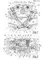
- FIG. 1 shows an internal combustion engine according to the invention, partly in section along the line I-I in FIG. 2, and FIG. 2 shows a plan view of part of the internal combustion engine according to FIG. 1.
- FIG. 1 Of the internal combustion engine according to the invention, essentially only the cylinder head 1 is shown in FIG. 1, which is attached to the cylinder block 3 with the interposition of a seal 2.
- two intake valves 6, each controlling intake openings 5.5 ⁇ , and an exhaust valve 8 assigned to an exhaust opening 7 are provided for each cylinder 4 of the in-line internal combustion engine.
- the two inlet openings 5 and 5 ⁇ , which open into the combustion chamber 12 arranged in the cylinder head 1, are arranged on one side of the plane 11 containing the cylinder axis 9 and extending parallel to the camshaft 10.
- the outlet opening 7 opens into the combustion chamber 12 on the opposite side of the level 11, and the spark plug 13 is located next to it.
- the camshaft 10 is eccentric to the plane 11, which eliminates a parameter that would restrict the design of the combustion chamber 12.
- rocker arm shafts 14 and 15 Parallel to the camshaft 10 lying between the intake and exhaust valves, two rocker arm shafts 14 and 15, each arranged at the same distance from the camshaft 10 on the cylinder head 1, are provided, with the two intake rocker arms 16 and 16 ⁇ being pivotally mounted on one rocker arm shaft 14, each by means of bearings 28 .
- the exhaust rocker arm 17 On the other rocker arm shaft 15 is the exhaust rocker arm 17, which is mounted in a completely identical manner.
- rocker arms are of identical design and each have at their outer end facing the shaft end 18 of an inlet or outlet valve an adjusting mechanism 19 which interacts with this shaft end 18, and at the opposite end one with the corresponding cam - inlet cam 20, 20 ⁇ or outlet cam 21 - engaged cam thumb 22.
- the adjusting mechanism 19 can consist of an adjusting screw as well as an automatic, hydraulic valve adjusting mechanism.
- Fig. 2 which includes only the area of a cylinder, it can be seen that the connecting line 23 between the cam thumb 22 and adjusting mechanism 19 of each rocker arm is pivoted in the same direction by the same angle ⁇ to the axis of rotation 24 or 25 of the rocker arm shaft 14 or 15.
- the cam thumb 22 of the inlet rocker arm 16 ⁇ accesses the inlet cam 20 ⁇ shown above in FIG. 2 next to the camshaft bearing 26.
- the next cam 20 in this order controls the second intake rocker arm 16, the exhaust cam 21 cooperating with the exhaust rocker arm 17 being arranged on the camshaft 10 between the intake cam 20 and a further camshaft bearing 26. All camshaft bearings 26 are fastened to the cylinder head 1 with screws 27.
- the same task is performed for the exhaust rocker arm by a compression spring 30 arranged on the rocker arm shaft 15.
- the two inlet channels are designated 31 and the outlet channel 32.
- the two inlet valves 6, have valve springs 33 and the outlet valve has a valve spring 34, which are each supported on spring plates 35 arranged at the shaft end 18 of the valves.
Landscapes
- Engineering & Computer Science (AREA)
- Mechanical Engineering (AREA)
- General Engineering & Computer Science (AREA)
- Chemical & Material Sciences (AREA)
- Combustion & Propulsion (AREA)
- Valve-Gear Or Valve Arrangements (AREA)
- Ignition Installations For Internal Combustion Engines (AREA)
Abstract
Description
- Die Erfindung bezieht sich auf eine Brennkraftmaschine mit pro Zylinder zwei nebeneinanderliegenden Einlaßventilen und einem gegenüberliegenden Auslaßventil, mit einer Nockenwelle, die zu den beiden Einlaßventilen und dem Auslaßventil den gleichen Abstand besitzt, wobei zwei parallel zur Nockenwelle verlaufende Kipphebelwellen zur Aufnahme der die Ventile betätigenden Kipphebel vorgesehen sind, und wobei die Verbindungslinie zwischen Nockendaumen und Einstellmechanismus eines Einlaßkipphebels und des Auslaßkipphebels bezüglich seiner Drehachse um den selben Winkel gleichsinnig gedreht ist.
- Eine Brennkraftmaschine der eingangs genannten Art, welche einen Ventilbetätigungsmechanismus zur Steuerung von zwei Ansaug- und einem Auslaßventil aufweist, ist aus der DE-OS 33 42 115 bekannt. Zwischen den beiden Einlaßventilen und dem Auslaßventil liegt eine einzige Nockenwelle, welche im wesentlichen gleichen Abstand von den Einlaßventilen und dem Auslaßventil aufweist. Die die Ventile betätigenden Nocken sind auf einer Nockenwelle angeordnet und stehen mit den Schaftenden der Einlaß- bzw. des Auslaßventiles durch zwei Einlaßkipphebel und einem Auslaßkipphebel in Verbindung, welche schwenkbar von Kipphebelwellen getragen werden. Einer der Einlaßkipphebel und der Auslaßkipphebel sind so geformt, daß sie die gleichen Abmessungen aufweisen, womit diese Kipphebel untereinander austauschbar sind. Das Einlaßkipphebelpaar besteht dabei aus einem links- und einem rechtsorientierten Kipphebel, d.h., die Verbindungslinie Mitte Nockendaumen zur Einstellschraube ist zur Drehachse des Kiphebels nach links oder rechts gedreht. Der Auslaßkipphebel ist entweder mit dem links- oder rechtsorientierten Einlaßkipphebel austauschbar. Ein Vierzylindermotor weist beispielsweise sechs rechtsorientierte und sechs linksorientierte Kipphebel auf, was von der Anzahl der verschiedenen Teile her einen Nachteil, insbesondere im Bezug auf die Bearbeitung bzw. Lagerhaltung darstellt.
- Zusätzlich ist bein der Brennkraftmaschine die Position der Zündkerze und des Auslaßventiles von Zylinder zu Zylinder unterschiedlich, nämlich um eine Querebene zwischen Zylinder 2 und 3 gespiegelt, was zusätzlich Schwierigkeiten bei der Herstellung des Zylinderkopfes verursacht.
- Aufgabe der vorliegenden Erfindung ist es, bei einer Brennkraftmaschine, welche drei Ventile pro Zylinder aufweist, die obengenannten Nachteile zu vermeiden und insbesondere eine Brennkraftmaschine zu schaffen, deren Ventilbetätigungsmechanismus einfacher herstellbar ist, wobei auch die Anzahl verschiedener Bauteile verringert werden soll.
- Diese Aufgabe wird erfindungsgemäß dadurch gelöst, daß die Verbindungslinie zwischen Nockendaumen und Einstellmechanismus auch des anderen Einlaßkipphebels und des Auslaßkipphebels bezüglich seiner Drehachse um den selben Winkel α gleichsinnig gedreht ist, wobei der das Auslaßventil betätigende Auslaßkipphebel zwischen dem Nockenwellenlager und jenem Einlaßkipphebel liegt, der das dem Auslaßventil gegenüberliegende Einlaßventil betätigt. Das den Einlaßventilen gegenüberliegende Auslaßventil wird somit nicht von einem zwischen dem Einlaßnocken liegenden Auslaßnocken betätigt, sondern von einem Auslaßnocken, der neben den beiden Einlaßnocken nahe dem Nockenwellenlager liegt. Damit wird bei optimaler Anordnung der Ventil im Zylinderkopf die Anzahl der verschiedenen Kipphebelbauarten auf nur eine einzige reduziert, indem beispielsweise für einen Vierzylindermotor zwölf linksorientierte Kipphebel verwendet werden, die zusätzlich in allen Längenabmessungen übereinstimmende Werte aufweisen und somit voll austauschbar sind. Neben einer vereinfachten Produktion - nur eine Ausführungsform muß hergestellt werden - wird somit auch die Lagerhaltung entsprechend vereinfact und verbilligt.
- Von Vorteil ist es weiters, wenn nach einem weiteren Merkmal der Erfindung die Einlaßventile, das Auslaßventil und die Zündkerze für alle Zylinder einer mehrzylindrigen Brennkraftmaschine deckungsgleich angeordnet sind. Neben der vorteilhaften Verwendung nur einer Kipphebelausführung wird durch diese Ausbildung auch die Herstellung des Zylinderkopfes vereinfacht, wobei beispielsweise bei V-Motoren die Zylinderköpfe zwar deckungsgleich aber durchaus um 180° gedreht ausgebildet sein können, sodaß dann die Auslaßkanäle jeweils an der äußeren Seite des Motorblocks liegen.
- Schließlich ist es erfindungsgemäß möglich, daß insbesondere bei einer Reihenbrennkraftmaschine die Anordnung der Einlaßventile und des Auslaßventiles, sowie der Zündkerze translationsinvariant gegenüber der Translation um den Abstand zweier Zylinder ist. Alle Bohrungs- bzw. Bearbeitungsvorgänge an einem derart ausgebildeten Zylinderkopf einer Reihenbrennkraftmaschine können somit jeweils nach einem Vorschub um einen Zylinderabstand völlig gleichartig ausgeführt werden.
- Ein weiterer Vorteil liegt in der Bearbeitung der Kolbenoberfläche, da auch allfällige Kolbenmulden bzw. Ventiltaschen völlig deckungsgleich ausgebildet werden können, wobei insbesondere bei Reihenbrennkraftmaschinen alle Kolben räumlich gleich orientiert in den Zylinderblock eingebaut werden können, was den Bestückungsvorgang entrsprechend vereinfact.
- Bei 3- bzw. 5-Zylinder-Reihenbrennkraftmaschinen stellt sich nun nich mehr das Problem, daß die Anzahl der rechts- bzw. linksorientierten Kipphebel differiert, wie bei herkömmlichen Brennkraftmaschinen, bei welchen dann natürlich auch eine Spiegelung um eine Querebene unmöglich ist.
- Im folgenden wird die Erfindung anhand einer Reihenbrennkraftmaschine näher erläutert.
- Fig. 1 zeigt eine Brennkraftmaschine nach der Erfindung teilweise geschnitten nach der Linie I-I in Fig. 2, und Fig. 2 eine Draufsicht auf einen Teil der Brennkraftmaschine nach Fig. 1.
- Von der erfindungsgemäßen Brennkraftmaschine ist in Fig. 1 im wesentlichen nur der Zylinderkopf 1 dargestellt, welcher unter Zwischenschaltung einer Dichtung 2 auf dem Zylinderblock 3 befestigt ist. Für jeden Zylinder 4 der Reihenbrennkraftmaschine sind zwei jeweils Einlaßöffnungen 5,5ʹ steuernde Einlaßventile 6 und ein einer Auslaßöffnung 7 zugeordnetes Auslaßventil 8 vorgesehen. Die beiden Einlaßöffnungen 5 und 5ʹ, welche in den im Zylinderkopf 1 angeordneten Brennraum 12 münden, sind dabei auf einer Seite der die Zylinderachse 9 beinhaltenden, zur Nockenwelle 10 parallel verlaufenden Ebene 11 angeordnet. Auf der gegenüberliegenden Seite der Ebene 11 mündet die Auslaßöffnung 7 in den Brennraum 12, daneben liegt die Zündkerze 13.
- Die Nockenwelle 10 liegt zur Ebene 11 exzentrisch, wodurch ein Parameter entfällt, der die Gestaltung des Brennraumes 12 einschränken würde.
- Parallel zur zwischen den Ein- und Auslaßventilen liegenden Nockenwelle 10 sind zwei jeweils im gleichen Abstand zur Nockenwelle 10 am Zylinderkopf 1 angeordnete Kipphebelwellen 14 und 15 vorgesehen, wobei auf der einen Kipphebelwelle 14 die beiden Einlaßkipphebel 16 und 16ʹ, jeweils mittels Lager 28 schwenkbar gelagert sind. Auf der anderen Kipphebelwelle 15 befindet sich der völlig gleichartig gelagerte Auslaßkipphebel 17.
- Alle Kipphebel sind identisch aufgebaut und weisen je an ihrem äußeren, dem Schaftende 18 eines Ein- oder Auslaßventiles zugewandten Ende einen mit diesem Schaftende 18 zusammenwirkenden Einstellmechanismus 19, sowie am gegenüberliegenden Ende einen mit dem entsprechenden Nocken - Einlaßnocken 20, 20ʹ bzw. Auslaßnocken 21 - im Eingriff stehenden Nockendaumen 22 auf. Der Einstellmechanismus 19 kann sowohl aus einer Einstellschraube als auch aus einem automatischen, hydraulischen Ventileinstellmechanismus bestehen.
- Aus der Fig. 2, welche nur den Bereich eines Zylinders umfaßt, ist ersichtlich, daß die Verbindungslinie 23 zwischen Nockendaumen 22 und Einstellmechanismus 19 jedes Kipphebels gleichsinning um den selben Winkel α zur Drehachse 24 bzw. 25 der Kipphebelwelle 14 bzw. 15 verschwenkt ist. Der Nockendaumen 22 des Einlaßkipphebels 16ʹ greift dabei auf den in Fig. 2 oben dargestellten Einlaßnocken 20ʹ neben dem Nockenwellenlager 26 zu. Der in dieser Reihenfolge nächste Nocken 20 steuert den zweiten Einlaßkipphebel 16, wobei zwischen dem Einlaßnokken 20 und einem weiteren Nockenwellenlager 26 der mit dem Auslaßkipphebel 17 zusammenwirkende Auslaßnocken 21 auf der Nockenwelle 10 angeordnet ist. Alle Nockenwellenlager 26 sind mit Schrauben 27 am Zylinderkopf 1 befestigt.
- Die beiden Einlaßkipphebel 16, 16ʹ werden durch eine zwischen den Kipphebeln auf der Kipphebelwelle 14 angeordnete Druckfeder 29 in der gewünschten Position gehalten. Die gleiche Aufgabe übernimmt für den Auslaßkipphebel eine auf der Kipphebelwelle 15 angeordnete Druckfeder 30.
- Es ist natürlich im Sinne der Erfindung auch möglich, die Position des Auslaßventiles 8 und der Zündkerze 13 zu vertauschen, sodaß dann der Auslaßnocken 21 zwischen den Einlaßnokken 20 und 20ʹ liegt. Es muß dafür gesorgt werden, daß alle Längenabmessungen der Kipphebel, sowie der Winkel α zwischen der Verbindungslinie 23 und der Drehachse 24 bzw. 25 gleich groß sind, um zu gewährleisten, daß alle Kipphebel untereinander austauschbar sind.
- Der Vollständigkeit halber sei noch erwähnt, daß die beiden Einlaßkanäle mit 31 und der Auslaßkanal mit 32 bezeichnet ist. Die beiden Einlaßventile 6, weisen Ventilfedern 33 und das Auslaßventil eine Ventilfeder 34 auf, welche sich jeweils an am Schaftende 18 der Ventile angeordneten Federteller 35 abstützen.
Claims (3)
Applications Claiming Priority (2)
| Application Number | Priority Date | Filing Date | Title |
|---|---|---|---|
| AT311786A AT404389B (de) | 1986-11-21 | 1986-11-21 | Brennkraftmaschine mit einer nockenwelle zum antrieb von pro zylinder zwei nebeneinanderliegenden einlassventilen und einem gegenüberliegenden auslassventil |
| AT3117/86 | 1986-11-21 |
Publications (2)
| Publication Number | Publication Date |
|---|---|
| EP0271475A1 true EP0271475A1 (de) | 1988-06-15 |
| EP0271475B1 EP0271475B1 (de) | 1990-09-12 |
Family
ID=3545565
Family Applications (1)
| Application Number | Title | Priority Date | Filing Date |
|---|---|---|---|
| EP19870890250 Expired - Lifetime EP0271475B1 (de) | 1986-11-21 | 1987-11-09 | Brennkraftmaschine mit pro Zylinder zwei nebeneinanderliegenden Einlassventilen und einem gegenüberliegenden Auslassventil |
Country Status (4)
| Country | Link |
|---|---|
| EP (1) | EP0271475B1 (de) |
| JP (1) | JPS63205409A (de) |
| AT (1) | AT404389B (de) |
| DE (1) | DE3764936D1 (de) |
Cited By (1)
| Publication number | Priority date | Publication date | Assignee | Title |
|---|---|---|---|---|
| DE4112496C1 (en) * | 1991-04-17 | 1992-08-27 | Mercedes-Benz Aktiengesellschaft, 7000 Stuttgart, De | Liq. cooled IC engine in-line cylinder head - has ideal line, inter-setting inlet valve centre axes at valve seats, is at specified angle to long cylinder head axis |
Families Citing this family (1)
| Publication number | Priority date | Publication date | Assignee | Title |
|---|---|---|---|---|
| JPH0278702U (de) * | 1988-12-02 | 1990-06-18 |
Citations (4)
| Publication number | Priority date | Publication date | Assignee | Title |
|---|---|---|---|---|
| FR2048182A6 (de) * | 1969-06-03 | 1971-03-19 | Citroen Sa | |
| EP0068336A1 (de) * | 1981-06-26 | 1983-01-05 | Bayerische Motoren Werke Aktiengesellschaft, Patentabteilung AJ-3 | Zweizylinder-Viertakt-Boxermotor, insbesondere fahrtwind-luftgekühlt für Motorräder |
| DE3342115A1 (de) * | 1982-11-24 | 1984-05-24 | Honda Giken Kogyo K.K., Tokio/Tokyo | Ventil-betaetigungsmechanismus einer drei-ventil-brennkraftmaschine |
| EP0187287A2 (de) * | 1984-12-10 | 1986-07-16 | Mazda Motor Corporation | Brennkraftmaschine |
Family Cites Families (1)
| Publication number | Priority date | Publication date | Assignee | Title |
|---|---|---|---|---|
| JPS5996405A (ja) * | 1982-11-24 | 1984-06-02 | Yamaha Motor Co Ltd | 頭上カム軸式多バルブエンジン |
-
1986
- 1986-11-21 AT AT311786A patent/AT404389B/de not_active IP Right Cessation
-
1987
- 1987-11-09 EP EP19870890250 patent/EP0271475B1/de not_active Expired - Lifetime
- 1987-11-09 DE DE8787890250T patent/DE3764936D1/de not_active Expired - Lifetime
- 1987-11-18 JP JP29165387A patent/JPS63205409A/ja active Pending
Patent Citations (4)
| Publication number | Priority date | Publication date | Assignee | Title |
|---|---|---|---|---|
| FR2048182A6 (de) * | 1969-06-03 | 1971-03-19 | Citroen Sa | |
| EP0068336A1 (de) * | 1981-06-26 | 1983-01-05 | Bayerische Motoren Werke Aktiengesellschaft, Patentabteilung AJ-3 | Zweizylinder-Viertakt-Boxermotor, insbesondere fahrtwind-luftgekühlt für Motorräder |
| DE3342115A1 (de) * | 1982-11-24 | 1984-05-24 | Honda Giken Kogyo K.K., Tokio/Tokyo | Ventil-betaetigungsmechanismus einer drei-ventil-brennkraftmaschine |
| EP0187287A2 (de) * | 1984-12-10 | 1986-07-16 | Mazda Motor Corporation | Brennkraftmaschine |
Cited By (1)
| Publication number | Priority date | Publication date | Assignee | Title |
|---|---|---|---|---|
| DE4112496C1 (en) * | 1991-04-17 | 1992-08-27 | Mercedes-Benz Aktiengesellschaft, 7000 Stuttgart, De | Liq. cooled IC engine in-line cylinder head - has ideal line, inter-setting inlet valve centre axes at valve seats, is at specified angle to long cylinder head axis |
Also Published As
| Publication number | Publication date |
|---|---|
| DE3764936D1 (de) | 1990-10-18 |
| ATA311786A (de) | 1998-03-15 |
| AT404389B (de) | 1998-11-25 |
| EP0271475B1 (de) | 1990-09-12 |
| JPS63205409A (ja) | 1988-08-24 |
Similar Documents
| Publication | Publication Date | Title |
|---|---|---|
| DE3436426C2 (de) | ||
| DE69030035T2 (de) | Auslassventilsteuervorrichtung für einen parallelen Mehrzylinder-Zweitaktmotor | |
| DE69027032T2 (de) | Nockenwellenanordnung für eine Mehrventil-Brennkraftmaschine | |
| DE4326159C2 (de) | Mehrzylindrige Brennkraftmaschine mit V-förmig angeordneten Zylinderreihen | |
| DE69017614T2 (de) | Zylinderkopf und Ventilanordnung für Mehrventil-Brennkraftmaschine. | |
| DE69314439T2 (de) | Ventiltrieb für Brennkraftmaschine | |
| DE3883501T2 (de) | Mehrventilzylinderkopf. | |
| DE69612087T2 (de) | Kipphebelvorrichtung für brennkraftmaschine | |
| DE4227566A1 (de) | Zylinderkopfseitiges Nockenwellenlager für eine mehrzylindrige Brennkraftmaschine | |
| DE69024117T2 (de) | Zylinderkopf-Schmiersystem einer Brennkraftmaschine | |
| DE69414557T2 (de) | Zylinderkopfanordnung für eine Mehrventil-Brennkraftmaschine mit obenliegender Nockenwelle | |
| DE10239224B4 (de) | Ventiltrieb für Doppelnockenwellenmotor mit drei Ventilen | |
| DE69016289T2 (de) | Ventiltriebeinrichtung für Brennkraftmaschine. | |
| DE69416923T2 (de) | Pneumatische Ventilvorrichtung für Brennkraftmaschine | |
| DE69016709T2 (de) | Ventil und Federanordnung für Brennkraftmaschine. | |
| DE69411413T2 (de) | Brennkraftmaschine | |
| EP0271475B1 (de) | Brennkraftmaschine mit pro Zylinder zwei nebeneinanderliegenden Einlassventilen und einem gegenüberliegenden Auslassventil | |
| EP0845582B1 (de) | Ventilsteuerung für eine mit Hubventilen zum Ladungswechsel ausgerüstete Brennkraftmaschine | |
| DE19745761A1 (de) | Variable Ventilsteuerung für Hubkolben-Brennkraftmaschinen | |
| DE3342115A1 (de) | Ventil-betaetigungsmechanismus einer drei-ventil-brennkraftmaschine | |
| DE3932293C1 (de) | ||
| EP0262250B1 (de) | Viertakt-Brennkraftmaschine | |
| DE19620546A1 (de) | Zylinderkopf für eine mehrzylindrige Brennkraftmaschine | |
| DE69003052T2 (de) | Zylinderkopf für eine Brennkraftmaschine mit fünf Ventilen pro Zylinder. | |
| DE4235103B4 (de) | Nockenwellen-Ventilsteuerung für eine Brennkraftmaschine mit zwei Zylinderreihen |
Legal Events
| Date | Code | Title | Description |
|---|---|---|---|
| PUAI | Public reference made under article 153(3) epc to a published international application that has entered the european phase |
Free format text: ORIGINAL CODE: 0009012 |
|
| AK | Designated contracting states |
Kind code of ref document: A1 Designated state(s): DE FR GB |
|
| GBC | Gb: translation of claims filed (gb section 78(7)/1977) | ||
| EL | Fr: translation of claims filed | ||
| 17P | Request for examination filed |
Effective date: 19880720 |
|
| 17Q | First examination report despatched |
Effective date: 19891010 |
|
| GRAA | (expected) grant |
Free format text: ORIGINAL CODE: 0009210 |
|
| AK | Designated contracting states |
Kind code of ref document: B1 Designated state(s): DE FR GB |
|
| ET | Fr: translation filed | ||
| GBT | Gb: translation of ep patent filed (gb section 77(6)(a)/1977) | ||
| REF | Corresponds to: |
Ref document number: 3764936 Country of ref document: DE Date of ref document: 19901018 |
|
| PLBE | No opposition filed within time limit |
Free format text: ORIGINAL CODE: 0009261 |
|
| STAA | Information on the status of an ep patent application or granted ep patent |
Free format text: STATUS: NO OPPOSITION FILED WITHIN TIME LIMIT |
|
| 26N | No opposition filed | ||
| PG25 | Lapsed in a contracting state [announced via postgrant information from national office to epo] |
Ref country code: GB Effective date: 19911109 |
|
| GBPC | Gb: european patent ceased through non-payment of renewal fee | ||
| PGFP | Annual fee paid to national office [announced via postgrant information from national office to epo] |
Ref country code: FR Payment date: 19921127 Year of fee payment: 6 |
|
| PG25 | Lapsed in a contracting state [announced via postgrant information from national office to epo] |
Ref country code: FR Effective date: 19940729 |
|
| REG | Reference to a national code |
Ref country code: FR Ref legal event code: ST |
|
| PGFP | Annual fee paid to national office [announced via postgrant information from national office to epo] |
Ref country code: DE Payment date: 19960126 Year of fee payment: 9 |
|
| PG25 | Lapsed in a contracting state [announced via postgrant information from national office to epo] |
Ref country code: DE Effective date: 19970801 |