EP0271630A2 - Medium für Informationsspeicherung und Verfahren zum Löschen von Information - Google Patents
Medium für Informationsspeicherung und Verfahren zum Löschen von Information Download PDFInfo
- Publication number
- EP0271630A2 EP0271630A2 EP87106531A EP87106531A EP0271630A2 EP 0271630 A2 EP0271630 A2 EP 0271630A2 EP 87106531 A EP87106531 A EP 87106531A EP 87106531 A EP87106531 A EP 87106531A EP 0271630 A2 EP0271630 A2 EP 0271630A2
- Authority
- EP
- European Patent Office
- Prior art keywords
- crystalline state
- recording layer
- phase crystalline
- information
- atomic
- Prior art date
- Legal status (The legal status is an assumption and is not a legal conclusion. Google has not performed a legal analysis and makes no representation as to the accuracy of the status listed.)
- Granted
Links
- 238000003860 storage Methods 0.000 title claims description 12
- 238000000034 method Methods 0.000 title claims description 5
- 239000010410 layer Substances 0.000 claims abstract description 86
- 230000009466 transformation Effects 0.000 claims abstract description 49
- 239000000956 alloy Substances 0.000 claims abstract description 36
- 229910045601 alloy Inorganic materials 0.000 claims abstract description 35
- 230000008018 melting Effects 0.000 claims abstract description 24
- 238000002844 melting Methods 0.000 claims abstract description 24
- 239000011241 protective layer Substances 0.000 claims abstract description 20
- 229910001245 Sb alloy Inorganic materials 0.000 claims abstract description 15
- 239000000758 substrate Substances 0.000 claims abstract description 14
- 239000002344 surface layer Substances 0.000 claims abstract description 7
- 239000011347 resin Substances 0.000 claims abstract description 5
- 229920005989 resin Polymers 0.000 claims abstract description 5
- 229910001152 Bi alloy Inorganic materials 0.000 claims description 9
- 229910015367 Au—Sb Inorganic materials 0.000 claims description 6
- 230000001131 transforming effect Effects 0.000 claims 2
- 230000003287 optical effect Effects 0.000 abstract description 16
- VYPSYNLAJGMNEJ-UHFFFAOYSA-N Silicium dioxide Chemical compound O=[Si]=O VYPSYNLAJGMNEJ-UHFFFAOYSA-N 0.000 abstract description 9
- 235000012239 silicon dioxide Nutrition 0.000 abstract description 4
- 229910052681 coesite Inorganic materials 0.000 abstract description 3
- 229910052906 cristobalite Inorganic materials 0.000 abstract description 3
- 239000000377 silicon dioxide Substances 0.000 abstract description 3
- 229910052682 stishovite Inorganic materials 0.000 abstract description 3
- 229910052905 tridymite Inorganic materials 0.000 abstract description 3
- 229920000515 polycarbonate Polymers 0.000 abstract 1
- 239000004417 polycarbonate Substances 0.000 abstract 1
- 239000013078 crystal Substances 0.000 description 9
- 239000000463 material Substances 0.000 description 6
- WPYVAWXEWQSOGY-UHFFFAOYSA-N indium antimonide Chemical compound [Sb]#[In] WPYVAWXEWQSOGY-UHFFFAOYSA-N 0.000 description 4
- 230000005855 radiation Effects 0.000 description 4
- 238000000151 deposition Methods 0.000 description 3
- 238000009792 diffusion process Methods 0.000 description 3
- 238000010438 heat treatment Methods 0.000 description 3
- 238000004544 sputter deposition Methods 0.000 description 3
- 230000015572 biosynthetic process Effects 0.000 description 2
- 150000004770 chalcogenides Chemical class 0.000 description 2
- 238000001816 cooling Methods 0.000 description 2
- 238000002425 crystallisation Methods 0.000 description 2
- 230000008025 crystallization Effects 0.000 description 2
- 238000010894 electron beam technology Methods 0.000 description 2
- 229920003229 poly(methyl methacrylate) Polymers 0.000 description 2
- 229920005668 polycarbonate resin Polymers 0.000 description 2
- 239000004431 polycarbonate resin Substances 0.000 description 2
- 239000004926 polymethyl methacrylate Substances 0.000 description 2
- 238000005204 segregation Methods 0.000 description 2
- 238000007711 solidification Methods 0.000 description 2
- 230000008023 solidification Effects 0.000 description 2
- 229910008772 Sn—Se Inorganic materials 0.000 description 1
- 230000015556 catabolic process Effects 0.000 description 1
- 230000000052 comparative effect Effects 0.000 description 1
- 230000008602 contraction Effects 0.000 description 1
- 238000007872 degassing Methods 0.000 description 1
- 238000006731 degradation reaction Methods 0.000 description 1
- 230000000593 degrading effect Effects 0.000 description 1
- 230000008021 deposition Effects 0.000 description 1
- 238000009826 distribution Methods 0.000 description 1
- 239000003822 epoxy resin Substances 0.000 description 1
- 239000011521 glass Substances 0.000 description 1
- 239000000203 mixture Substances 0.000 description 1
- 238000005191 phase separation Methods 0.000 description 1
- 229920000647 polyepoxide Polymers 0.000 description 1
- 239000010453 quartz Substances 0.000 description 1
- 239000004065 semiconductor Substances 0.000 description 1
- 238000004904 shortening Methods 0.000 description 1
- 238000007782 splat cooling Methods 0.000 description 1
- 238000000844 transformation Methods 0.000 description 1
- 239000012780 transparent material Substances 0.000 description 1
Images

Classifications
-
- G—PHYSICS
- G11—INFORMATION STORAGE
- G11B—INFORMATION STORAGE BASED ON RELATIVE MOVEMENT BETWEEN RECORD CARRIER AND TRANSDUCER
- G11B7/00—Recording or reproducing by optical means, e.g. recording using a thermal beam of optical radiation by modifying optical properties or the physical structure, reproducing using an optical beam at lower power by sensing optical properties; Record carriers therefor
- G11B7/24—Record carriers characterised by shape, structure or physical properties, or by the selection of the material
- G11B7/241—Record carriers characterised by shape, structure or physical properties, or by the selection of the material characterised by the selection of the material
- G11B7/242—Record carriers characterised by shape, structure or physical properties, or by the selection of the material characterised by the selection of the material of recording layers
- G11B7/243—Record carriers characterised by shape, structure or physical properties, or by the selection of the material characterised by the selection of the material of recording layers comprising inorganic materials only, e.g. ablative layers
- G11B7/2433—Metals or elements of Groups 13, 14, 15 or 16 of the Periodic Table, e.g. B, Si, Ge, As, Sb, Bi, Se or Te
-
- G—PHYSICS
- G11—INFORMATION STORAGE
- G11B—INFORMATION STORAGE BASED ON RELATIVE MOVEMENT BETWEEN RECORD CARRIER AND TRANSDUCER
- G11B7/00—Recording or reproducing by optical means, e.g. recording using a thermal beam of optical radiation by modifying optical properties or the physical structure, reproducing using an optical beam at lower power by sensing optical properties; Record carriers therefor
- G11B7/004—Recording, reproducing or erasing methods; Read, write or erase circuits therefor
- G11B7/0055—Erasing
- G11B7/00557—Erasing involving phase-change media
-
- G—PHYSICS
- G11—INFORMATION STORAGE
- G11B—INFORMATION STORAGE BASED ON RELATIVE MOVEMENT BETWEEN RECORD CARRIER AND TRANSDUCER
- G11B7/00—Recording or reproducing by optical means, e.g. recording using a thermal beam of optical radiation by modifying optical properties or the physical structure, reproducing using an optical beam at lower power by sensing optical properties; Record carriers therefor
- G11B7/24—Record carriers characterised by shape, structure or physical properties, or by the selection of the material
- G11B7/241—Record carriers characterised by shape, structure or physical properties, or by the selection of the material characterised by the selection of the material
- G11B7/242—Record carriers characterised by shape, structure or physical properties, or by the selection of the material characterised by the selection of the material of recording layers
- G11B7/243—Record carriers characterised by shape, structure or physical properties, or by the selection of the material characterised by the selection of the material of recording layers comprising inorganic materials only, e.g. ablative layers
-
- G—PHYSICS
- G11—INFORMATION STORAGE
- G11B—INFORMATION STORAGE BASED ON RELATIVE MOVEMENT BETWEEN RECORD CARRIER AND TRANSDUCER
- G11B7/00—Recording or reproducing by optical means, e.g. recording using a thermal beam of optical radiation by modifying optical properties or the physical structure, reproducing using an optical beam at lower power by sensing optical properties; Record carriers therefor
- G11B7/24—Record carriers characterised by shape, structure or physical properties, or by the selection of the material
- G11B7/241—Record carriers characterised by shape, structure or physical properties, or by the selection of the material characterised by the selection of the material
- G11B7/242—Record carriers characterised by shape, structure or physical properties, or by the selection of the material characterised by the selection of the material of recording layers
- G11B7/243—Record carriers characterised by shape, structure or physical properties, or by the selection of the material characterised by the selection of the material of recording layers comprising inorganic materials only, e.g. ablative layers
- G11B2007/24302—Metals or metalloids
- G11B2007/24308—Metals or metalloids transition metal elements of group 11 (Cu, Ag, Au)
-
- G—PHYSICS
- G11—INFORMATION STORAGE
- G11B—INFORMATION STORAGE BASED ON RELATIVE MOVEMENT BETWEEN RECORD CARRIER AND TRANSDUCER
- G11B7/00—Recording or reproducing by optical means, e.g. recording using a thermal beam of optical radiation by modifying optical properties or the physical structure, reproducing using an optical beam at lower power by sensing optical properties; Record carriers therefor
- G11B7/24—Record carriers characterised by shape, structure or physical properties, or by the selection of the material
- G11B7/241—Record carriers characterised by shape, structure or physical properties, or by the selection of the material characterised by the selection of the material
- G11B7/242—Record carriers characterised by shape, structure or physical properties, or by the selection of the material characterised by the selection of the material of recording layers
- G11B7/243—Record carriers characterised by shape, structure or physical properties, or by the selection of the material characterised by the selection of the material of recording layers comprising inorganic materials only, e.g. ablative layers
- G11B2007/24302—Metals or metalloids
- G11B2007/2431—Metals or metalloids group 13 elements (B, Al, Ga, In)
-
- G—PHYSICS
- G11—INFORMATION STORAGE
- G11B—INFORMATION STORAGE BASED ON RELATIVE MOVEMENT BETWEEN RECORD CARRIER AND TRANSDUCER
- G11B7/00—Recording or reproducing by optical means, e.g. recording using a thermal beam of optical radiation by modifying optical properties or the physical structure, reproducing using an optical beam at lower power by sensing optical properties; Record carriers therefor
- G11B7/24—Record carriers characterised by shape, structure or physical properties, or by the selection of the material
- G11B7/241—Record carriers characterised by shape, structure or physical properties, or by the selection of the material characterised by the selection of the material
- G11B7/242—Record carriers characterised by shape, structure or physical properties, or by the selection of the material characterised by the selection of the material of recording layers
- G11B7/243—Record carriers characterised by shape, structure or physical properties, or by the selection of the material characterised by the selection of the material of recording layers comprising inorganic materials only, e.g. ablative layers
- G11B2007/24302—Metals or metalloids
- G11B2007/24314—Metals or metalloids group 15 elements (e.g. Sb, Bi)
-
- G—PHYSICS
- G11—INFORMATION STORAGE
- G11B—INFORMATION STORAGE BASED ON RELATIVE MOVEMENT BETWEEN RECORD CARRIER AND TRANSDUCER
- G11B7/00—Recording or reproducing by optical means, e.g. recording using a thermal beam of optical radiation by modifying optical properties or the physical structure, reproducing using an optical beam at lower power by sensing optical properties; Record carriers therefor
- G11B7/24—Record carriers characterised by shape, structure or physical properties, or by the selection of the material
- G11B7/241—Record carriers characterised by shape, structure or physical properties, or by the selection of the material characterised by the selection of the material
- G11B7/252—Record carriers characterised by shape, structure or physical properties, or by the selection of the material characterised by the selection of the material of layers other than recording layers
- G11B7/253—Record carriers characterised by shape, structure or physical properties, or by the selection of the material characterised by the selection of the material of layers other than recording layers of substrates
- G11B7/2533—Record carriers characterised by shape, structure or physical properties, or by the selection of the material characterised by the selection of the material of layers other than recording layers of substrates comprising resins
- G11B7/2534—Record carriers characterised by shape, structure or physical properties, or by the selection of the material characterised by the selection of the material of layers other than recording layers of substrates comprising resins polycarbonates [PC]
-
- G—PHYSICS
- G11—INFORMATION STORAGE
- G11B—INFORMATION STORAGE BASED ON RELATIVE MOVEMENT BETWEEN RECORD CARRIER AND TRANSDUCER
- G11B7/00—Recording or reproducing by optical means, e.g. recording using a thermal beam of optical radiation by modifying optical properties or the physical structure, reproducing using an optical beam at lower power by sensing optical properties; Record carriers therefor
- G11B7/24—Record carriers characterised by shape, structure or physical properties, or by the selection of the material
- G11B7/241—Record carriers characterised by shape, structure or physical properties, or by the selection of the material characterised by the selection of the material
- G11B7/252—Record carriers characterised by shape, structure or physical properties, or by the selection of the material characterised by the selection of the material of layers other than recording layers
- G11B7/254—Record carriers characterised by shape, structure or physical properties, or by the selection of the material characterised by the selection of the material of layers other than recording layers of protective topcoat layers
- G11B7/2542—Record carriers characterised by shape, structure or physical properties, or by the selection of the material characterised by the selection of the material of layers other than recording layers of protective topcoat layers consisting essentially of organic resins
-
- G—PHYSICS
- G11—INFORMATION STORAGE
- G11B—INFORMATION STORAGE BASED ON RELATIVE MOVEMENT BETWEEN RECORD CARRIER AND TRANSDUCER
- G11B7/00—Recording or reproducing by optical means, e.g. recording using a thermal beam of optical radiation by modifying optical properties or the physical structure, reproducing using an optical beam at lower power by sensing optical properties; Record carriers therefor
- G11B7/24—Record carriers characterised by shape, structure or physical properties, or by the selection of the material
- G11B7/241—Record carriers characterised by shape, structure or physical properties, or by the selection of the material characterised by the selection of the material
- G11B7/252—Record carriers characterised by shape, structure or physical properties, or by the selection of the material characterised by the selection of the material of layers other than recording layers
- G11B7/257—Record carriers characterised by shape, structure or physical properties, or by the selection of the material characterised by the selection of the material of layers other than recording layers of layers having properties involved in recording or reproduction, e.g. optical interference layers or sensitising layers or dielectric layers, which are protecting the recording layers
Definitions
- the present invention relates to an information storage medium such as a so-called erasable optical disk having a recording layer irradiated with a beam to cause changes in optical characteristics, thereby writing information therein or erasing it therefrom.
- Some conventional erasable optical disks subjected to information erasure in addition to information read/write access utilize transformation between crystalline and amorphous phases.
- the recording layer is local strictlyly applied to a beam to cause a transformation between the crystalline and amorphous phases in the applied site and to read information by utilizing different complex indices of refraction of the phases.
- the optical disk is made of a material easily transformed into an amorphous phase upon beam radiation and subsequent rapid cooling.
- Such materials are chalcogenide-based materials such as TeO x , Te-Sn-Se, and Ge-Te (see “Erasable Large-Capacity Optical Disk", ll6th research meeting, l3lst committee, the Japan Society for the Promotion of Science (May, l983), for TeO x ).
- the amorphous phase of chalcogenide-based materials is not stable, and stable information recording cannot be performed. Moreover, if a material having a high crystallization temperature is used in order to stabilize the amorphous phase, it takes a long period of time to cause a transformation from the amorphous phase to the crystalline phase in the information erase mode.
- An information storage medium comprises: a transparent substrate; and a recording layer disposed on the substrate, which comprises an alloy having a melting point of 200 to 900°C and being capable of undergoing a phase transformation between a stable phase crystalline state and a metastable phase crystalline state; wherein the recording layer is exposed to a light beam to cause the phase transformation between the stable phase crystalline state and the metastable phase crystalline state in a site exposed to the beam, thereby writing information therein and erasing information therefrom.
- An information storage medium comprises: a transparent substrate; a recording layer which comprises an alloy, having a melting point of 200 to 900°C and being capable of undergoing a phase transformation between a stable phase crystalline state and a metastable phase crystalline state; a first protective layer disposed between the substrate and the recording layer; and a second protective layer disposed on the recording layer; wherein the recording layer is exposed to a light beam to cause the phase transformation between the stable phase crystalline state and the metastable phase crystalline state in a site exposed to the beam, thereby writing information therein and erasing information therefrom.
- a method of erasing information comprises: providing an information storage medium comprising a transparent substrate, and a recording layer comprising an alloy having a melting point of 200 to 900°C and capable of undergoing a phase transformation between a stable phase crystalline state and a metastable phase crystalline state, the recording layer being provided with a recording mark in the stable phase crystalline state; and applying a light beam to the recording mark to heat it to a temperature higher than a temperature of phase transformation between the stable and metastable phases but lower than the melting point of the recording layer, thereby causing the phase transformation from the metastable phase crystalline state to the stable phase crystalline state and hence erasing the information.
- information can be written and erased by a phase transformation between the crystalline phases in an alloy constituting the recording layer.
- the crystalline phase is stably maintained in both the stable and metastable states at room temperature. Therefore, the recorded information can be stored stably. Furthermore, since the melting point of the alloy constituting the recording layer is relatively low, the phase transformation temperatures are accordingly low. Moreover diffusion of atoms required for the phase transformation between the crystalline phases is comparatively little. Therefore, the site of the recording layer, applied with the beam, is subjected to the phase transformation in a very short period of time, and thus information can be recorded and erased at high speed.
- the major surfaces of the recording layer are covered by the protective layers, and the recording layer can be effectively protected from damage caused by beam radiation. As a result, information can be stored with still higher stability.
- the light beam can be applied to the recording mark to heat it to a temperature higher than the phase transformation temperature but lower than the melting point of the recording layer, thereby erasing the information.
- the phase transformation temperature is very low.
- a light beam having a low output can be used to erase the information at a higher speed.
- information can be erased with the light beam having a low output without causing melting of the recording mark. Therefore, the erasure portion is not degraded, and repetition of recording and erasure does not degrade the recording characteristics.
- Fig. l is a sectional view of an information storage medium (optical disk) according to an embodiment of the present invention.
- Substrate l is made of a transparent material which is not easily deteriorated over time and is exemplified by glass, quartz, polymethylmethacrylate (PMMA) resin, polycarbonate resin (PC), or epoxy resin.
- Protective layer 2, recording layer 3, and protective layers 4 and surface layer 5 are formed on substrate l in the order named.
- Protective layers 2 and 4 sandwich recording layer 3 therebetween.
- Protective layers 2 and 4 need not be formed. However, formation of these layers prevents scattering of recording layer 3 and formation of holes therein by applying of a laser beam.
- Protective layers 2 and 4 may be formed by depositing or sputtering a dielectric such as SiO2, SiO, or AlN.
- the thickness of each of protective layers 2 and 4 preferably falls within the range of l nm to l0 ⁇ m.
- Surface layer 5 is formed to prevent recording layer 3 from damage such as scratches during handling of the optical disk.
- Surface layer 5 is formed of a material having high adhesion strength with protective layer 4.
- Surface layer 5 can be formed by applying an ultraviolet (UV) curing resin on protective layer 4 and curing the resin upon radiation of ultraviolet rays.
- UV ultraviolet
- Recording layer 3 is made of an alloy having a melting point of 200 to 900°C and being capable of undergoing a phase transformation between a stable phase crystalline state and a metastable phase crystalline state, when a light beam, such as a laser beam, is applied to recording layer 3.
- the phase transformation temperature of the alloy is lower than the melting point thereof. Therefore, if the melting point of the alloy is lower than 200°C, a phase transformation tends to occur at a low temperature, thereby degrading storage characteristics of information at room temperature. If the melting point is higher than 900°C, a phase transformation requires a long period of time.
- Examples of such an alloy are an Au-Bi alloy containing 70 to 80 atomic% of Bi, an Au-Bi alloy containing 55 to 65 atomic% of Bi, an Au-Bi alloy containing 45 to 55 atomic% of Bi, an Au-Sb alloy containing 5 to 25 atomic% of Sb, an Au-Sb alloy containing 70 to 90 atomic% of Sb, an In-Sb alloy containing 30 to 45 atomic% of Sb, an In-Sb alloy containing 50 to 80% of Sb, a Pb-Sb alloy containing 30 to 40 atomic% of Sb, and a Pb-Sb alloy containing 40 to 70 atomic% of Sb.
- These alloys have low melting points as described above and can be easily melted with radiation of a low-output light beam.
- the alloy In order to transform the phase of such an alloy from the stable phase crystalline state to the metastable phase crystalline state, the alloy is melted to prevent remaining of stable-phase components and then rapidly cooled.
- the melting point of the alloy since the melting point of the alloy is low, melting can be performed in a very short period of time.
- the phase of the alloy can be transformed from the stable phase to the metastable phase in a very short period of time.
- the temperature of phase transformation between the stable and metastable phases is as low as l00 to 300°C.
- the alloy can be heated to a temperature as low as l00 to 300°C in order to transform this portion into a stable phase crystalline state, thus achieving a phase transformation in a very short period of time.
- the phase transformation is limited to that between crystalline phases, and is not attended with phase separation therefore diffusion of atoms required for the phase transformation can be comparatively little, thus further shortening the phase transformation time.
- the above alloys are stable at room temperature even in a metastable crystalline state, since the phase transformation temperature of alloys is higher than room temperature.
- recording layer 3 is applied to a laser beam having predetermined conditions and is melted.
- the layer is rapidly cooled according to splat cooling or the like to change the stable phase crystalline state to the ⁇ -phase (metastable phase) crystalline state.
- the ⁇ -phase alloy is applied to a laser beam having predetermined conditions and is heated to a temperature higher than the phase transformation temperature, the ⁇ -phase crystalline state is transformed back into the stable phase crystalline state. In this case, the ⁇ -phase crystalline state is transformed into the stable phase crystalline state at a temperature as low as l00 to 300°C but is stable at room temperature.
- the thickness of recording layer 3 preferably falls within the range of l nm to 5 ⁇ m.
- Layer 3 can be formed by multi-element co-sputtering or co-deposition using elements constituting the alloy. Layer 3 may be formed by sputtering or deposition using a single alloy material.
- optical disk As shown in Fig. l, light beam 8 such as a laser beam emitted from a light source (not shown) is focused by lens 7, and recording layer 3 is exposed to the focused laser beam from the side of substrate l.
- light beam 8 such as a laser beam emitted from a light source (not shown) is focused by lens 7, and recording layer 3 is exposed to the focused laser beam from the side of substrate l.
- recording layer 3 In order to record information, recording layer 3 must be maintained in a stable phase crystalline state. If the formed recording layer is held in the amorphous or metastable crystalline state, the layer must be converted into the stable phase crystalline state prior to use of the optical disk.
- Initialization of the optical disk is performed as follows. Recording layer 3 is heated to temperature exceeding the crystallization temperature (if the layer is amorphous) or to a temperature exceeding the phase transformation temperature for changing the metastable phase crystalline state into the stable phase crystalline state (if the layer has the metastable phase). Heating of recording layer 3 in the metastable phase crystalline state may be performed until recording layer 3 is melted. Heating may be performed using a heater, or the light beam is applied to the entire surface of recording layer 3. After heating, recording layer 3 is gradually cooled to prevent phase transformation into an amorphous state or a metastable phase.
- recording layer 3 maintained in the stable phase crystalline state is selectively applied to a laser beam to melt only beam-applied site 6.
- Beam-applied site 6 is rapidly cooled to transform its state into a metastable phase crystalline state.
- Beam-applied site 6 serves as a recording mark.
- the light beam is preferably a pulsed laser beam having a short period of l0 nsec to 2 ⁇ sec.
- the output power of the laser beam is set to melt beam-applied site 6 by one pulse. When a conventional semiconductor laser is used, the output power falls within the range of 5 to 30 mW.
- rapid cooling of the recording mark (site 6) this site is transformed into the metastable phase crystal state. In other words, information is written in site 6.
- the metastable phase crystal is stable at room temperature and thus information can be stored stably.
- Information recorded in recording layer 3 can be read from the recording mark (beam-applied site 6) exposed to a laser beam by detecting an intensity of light reflected by the recording site. Since the reflectance of the surface as the stable phase crystal is different from that of the surface as the metastable phase crystal, the difference between beam densities reflected by these surfaces is detected to determine whether the beam is reflected by the stable or metastable phase crystal.
- the recording mark (site 6) of recording layer 3 is exposed to a laser beam having a power smaller than that in the information recording mode, and is heated to a temperature lower than the melting point of the alloy constituting recording layer 3 but higher than the temperature of phase transformation from the metastable phase crystalline state to the stable phase crystalline state.
- the recording mark 6 of recording layer 3 is transformed into the stable phase crystal, thus erasing information from the recording mark 6.
- the entire disk may be heated to a temperature exceeding the phase transformation temperature by a heater or the like.
- only beam-applied site 6 of recording layer 3 may be sequentially applied to a laser beam spot.
- the phase transformation from the metastable phase crystal to the stable phase crystal requires only a short period of time as compared with the transformation from the amorphous phase to the crystalline phase since the phase transformation temperature is low and comparative little diffusion of atoms is required. Therefore, information can be erased at high speed.
- the alloy forming recording layer 3 has a melting point of 200 to 900°C. Moreover, recording layer 3 is heated to a temperature lower than the melting point thereof to undergo the phase transformation from the metastable phase to the stable phase. Therefore, the light beam having a low output can be used to erase the information at a higher speed.
- the recording mark is melted and then rapidly cooled to erase information
- a light beam having a high output is required and degassing and solidification contraction occur at the time of alloy solidification. Therefore, the erasure portion is deformed and cracked. If recording and erasing are repeated, the erasing portion is greatly degraded.
- the above conventional problem is not posed. Even if recording and erasing are repeatedly performed, degradation of the recording characteristics can be minimized.
- a sample is prepared by forming a recording layer of a thin In-Sb alloy film and a recording mark is formed in the recording layer. Under these conditions, the recording layer is analyzed by TEM-XMA and electron beam diffraction.
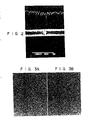
- Fig. 2 is a photograph showing results of linear analysis of Sb in the recording mark of the sample by TEM-XMA. According to this photograph, segregation of Sb is not found in the recording mark.
- Fig. 3A is a photograph showing results of In planar analysis of the recording layer of the sample by TEM-XMA
- Fig. 3B is a photograph showing results of Sb planar analysis. Segregation of In and Sb is not found in the recording mark and recording track having no information therein.
- Table l shows analytic results of the recording track having no information therein and the recording mark according to electron beam diffraction.
- the main phase of the recording site was a coarse metastable ⁇ -phase, and the central portion of recording track having no information was an InSb fine crystal.
- the In and Sb distributions of the recording layer are substantially uniform. Since the recording mark had the ⁇ -phase and the recording track central portion having no information was fine InSb, it was confirmed that information recording and erasing were caused by the phase transformation between the stable and metastable phase crystalline states and that the composition of the recording layer itself did not change.
Landscapes
- Chemical & Material Sciences (AREA)
- Inorganic Chemistry (AREA)
- Thermal Transfer Or Thermal Recording In General (AREA)
- Optical Record Carriers And Manufacture Thereof (AREA)
Applications Claiming Priority (2)
| Application Number | Priority Date | Filing Date | Title |
|---|---|---|---|
| JP61301485A JPS63155436A (ja) | 1986-12-19 | 1986-12-19 | 情報記録再生消去方法 |
| JP301485/86 | 1986-12-19 |
Publications (3)
| Publication Number | Publication Date |
|---|---|
| EP0271630A2 true EP0271630A2 (de) | 1988-06-22 |
| EP0271630A3 EP0271630A3 (en) | 1989-09-13 |
| EP0271630B1 EP0271630B1 (de) | 1993-02-17 |
Family
ID=17897474
Family Applications (1)
| Application Number | Title | Priority Date | Filing Date |
|---|---|---|---|
| EP87106531A Expired - Lifetime EP0271630B1 (de) | 1986-12-19 | 1987-05-06 | Medium für Informationsspeicherung und Verfahren zum Löschen von Information |
Country Status (5)
| Country | Link |
|---|---|
| US (1) | US4860274A (de) |
| EP (1) | EP0271630B1 (de) |
| JP (1) | JPS63155436A (de) |
| KR (1) | KR910001334B1 (de) |
| DE (1) | DE3784227T2 (de) |
Cited By (4)
| Publication number | Priority date | Publication date | Assignee | Title |
|---|---|---|---|---|
| EP0458604A3 (en) * | 1990-05-22 | 1992-07-01 | Canon Kabushiki Kaisha | Medium and related method and apparatus for recording and reproducing information in cells using multiple interference |
| EP0410704B1 (de) * | 1989-07-28 | 1995-10-04 | Matsushita Electric Industrial Co., Ltd. | Optisches Aufzeichnungsgerät |
| EP1369860A3 (de) * | 2002-05-31 | 2005-07-27 | TDK Corporation | Optisches Aufzeichnungsmedium |
| US7083894B2 (en) | 2002-06-14 | 2006-08-01 | Tdk Corporation | Optical recording medium |
Families Citing this family (12)
| Publication number | Priority date | Publication date | Assignee | Title |
|---|---|---|---|---|
| JPH01224939A (ja) * | 1988-03-04 | 1989-09-07 | Mitsubishi Metal Corp | 相変化型光ディスクの記録媒体用合金薄膜 |
| EP0337806B1 (de) * | 1988-04-14 | 1994-11-30 | Fuji Photo Film Co., Ltd. | Verfahren zum Wiederschreiben von Informationen auf ein Aufzeichnungsmedium |
| NL8801327A (nl) * | 1988-05-24 | 1989-12-18 | Philips Nv | Methode voor het optisch aftasten van een informatievlak en optische registratiedragers en aftastinrichtingen geschikt voor toepassing van de methode. |
| US5191565A (en) * | 1989-06-19 | 1993-03-02 | Matsushita Electric Industrial Co., Ltd. | Optical information recording medium |
| JP2556183B2 (ja) * | 1990-09-11 | 1996-11-20 | 富士ゼロックス株式会社 | 光学的記録方法とこの方法を用いる光記録媒体 |
| US5714748A (en) * | 1992-10-02 | 1998-02-03 | Goldstar Co., Ltd. | Magnetic cards employing optical recording material |
| JP3434419B2 (ja) * | 1996-08-09 | 2003-08-11 | パイオニア株式会社 | 記録媒体とその読み出し装置 |
| EP1369256B1 (de) | 2001-03-06 | 2010-04-14 | Mitsubishi Kagaku Media Co., Ltd. | Optisches informationsaufzeichnungsmaterial und aufzeichnungs-/erlöschungsverfahren |
| AU2003255928A1 (en) * | 2002-08-28 | 2004-03-19 | Koninklijke Philips Electronics N.V. | Rewritable optical data storage medium and use of such a medium |
| TWI226058B (en) * | 2002-09-11 | 2005-01-01 | Tdk Corp | Optical recording medium |
| US7801004B2 (en) * | 2005-10-31 | 2010-09-21 | Hewlett-Packard Development Company, L.P. | Method of error correction for a series of marks on an optical disc |
| US8031518B2 (en) * | 2009-06-08 | 2011-10-04 | Micron Technology, Inc. | Methods, structures, and devices for reducing operational energy in phase change memory |
Family Cites Families (17)
| Publication number | Priority date | Publication date | Assignee | Title |
|---|---|---|---|---|
| US3530441A (en) * | 1969-01-15 | 1970-09-22 | Energy Conversion Devices Inc | Method and apparatus for storing and retrieving information |
| US3801966A (en) * | 1971-08-18 | 1974-04-02 | Hitachi Ltd | Optical memory device |
| US3971874A (en) * | 1973-08-29 | 1976-07-27 | Matsushita Electric Industrial Co., Ltd. | Optical information storage material and method of making it |
| US4340655A (en) * | 1980-06-18 | 1982-07-20 | Eastman Kodak Company | Thermal and mechanical barrier layers for optical recording elements |
| JPS5968844A (ja) * | 1982-10-14 | 1984-04-18 | Matsushita Electric Ind Co Ltd | 光学的可逆記録再生装置 |
| JPS60177446A (ja) * | 1984-02-23 | 1985-09-11 | Nippon Telegr & Teleph Corp <Ntt> | 光デイスク記録媒体 |
| JPH066393B2 (ja) * | 1984-03-07 | 1994-01-26 | 株式会社日立製作所 | 情報の記録・消去方法 |
| US4718053A (en) * | 1984-11-09 | 1988-01-05 | Hitachi, Ltd. | Optical information apparatus and method of recording and erasing information |
| JPS61133065A (ja) * | 1984-12-03 | 1986-06-20 | Hitachi Ltd | 光情報記録装置 |
| JPS61134944A (ja) * | 1984-12-05 | 1986-06-23 | Fujitsu Ltd | 光学的情報記憶媒体 |
| CN1008845B (zh) * | 1984-12-05 | 1990-07-18 | 富士通株式会社 | 光学信息记录介质及信息的记录与擦抹的方法 |
| DE3581522D1 (de) * | 1984-12-28 | 1991-02-28 | Toshiba Kawasaki Kk | Auswechselbares speichersystem. |
| JPH0734267B2 (ja) * | 1985-05-24 | 1995-04-12 | 松下電器産業株式会社 | 可逆的光学情報記録媒体および記録再生方法 |
| US4660175A (en) * | 1985-07-08 | 1987-04-21 | Energy Conversion Devices, Inc. | Data storage device having novel barrier players encapsulating the data storage medium |
| US4667309A (en) * | 1985-07-08 | 1987-05-19 | Energy Conversion Devices, Inc. | Erasure means |
| US4744055A (en) * | 1985-07-08 | 1988-05-10 | Energy Conversion Devices, Inc. | Erasure means and data storage system incorporating improved erasure means |
| US4803660A (en) * | 1986-02-28 | 1989-02-07 | Kabushiki Kaisha Toshiba | Optical recording medium |
-
1986
- 1986-12-19 JP JP61301485A patent/JPS63155436A/ja active Pending
-
1987
- 1987-05-06 DE DE8787106531T patent/DE3784227T2/de not_active Expired - Lifetime
- 1987-05-06 EP EP87106531A patent/EP0271630B1/de not_active Expired - Lifetime
- 1987-05-06 US US07/046,543 patent/US4860274A/en not_active Expired - Lifetime
- 1987-12-19 KR KR1019870014544A patent/KR910001334B1/ko not_active Expired
Cited By (5)
| Publication number | Priority date | Publication date | Assignee | Title |
|---|---|---|---|---|
| EP0410704B1 (de) * | 1989-07-28 | 1995-10-04 | Matsushita Electric Industrial Co., Ltd. | Optisches Aufzeichnungsgerät |
| EP0458604A3 (en) * | 1990-05-22 | 1992-07-01 | Canon Kabushiki Kaisha | Medium and related method and apparatus for recording and reproducing information in cells using multiple interference |
| US5786117A (en) * | 1990-05-22 | 1998-07-28 | Canon Kabushiki Kaisha | Medium and related method and apparatus for recording and reproducing information in cells using multiple interference |
| EP1369860A3 (de) * | 2002-05-31 | 2005-07-27 | TDK Corporation | Optisches Aufzeichnungsmedium |
| US7083894B2 (en) | 2002-06-14 | 2006-08-01 | Tdk Corporation | Optical recording medium |
Also Published As
| Publication number | Publication date |
|---|---|
| US4860274A (en) | 1989-08-22 |
| KR880008263A (ko) | 1988-08-30 |
| DE3784227T2 (de) | 1993-08-26 |
| JPS63155436A (ja) | 1988-06-28 |
| EP0271630A3 (en) | 1989-09-13 |
| DE3784227D1 (de) | 1993-03-25 |
| EP0271630B1 (de) | 1993-02-17 |
| KR910001334B1 (ko) | 1991-03-04 |
Similar Documents
| Publication | Publication Date | Title |
|---|---|---|
| US4947372A (en) | Optical information memory medium for recording and erasing information | |
| USRE36383E (en) | Optical recording medium and production process for the medium | |
| EP0224313B1 (de) | Verfahren zur optischen Aufzeichnung von Information und ein optisches Aufzeichnungselement, das in diesem Verfahren benutzt wird | |
| EP0271630B1 (de) | Medium für Informationsspeicherung und Verfahren zum Löschen von Information | |
| EP0260920B1 (de) | Amorphe optische Aufzeichnungsfilme vom Dünnschichttyp | |
| MXPA01013105A (es) | Medio optico de grabacion y el uso de dicho medio optico de grabacion. | |
| EP0474311A1 (de) | Optischer Aufzeichnungsträger für Daten, Verfahren zum Schreiben und Lesen von Daten und Vorrichtung zum Aufzeichnen von Daten | |
| EP1030292B1 (de) | Optischer Aufzeichnungsträger und Verfahren zu dessen Initialisierung | |
| JPH08153339A (ja) | 光ディスク | |
| KR100586874B1 (ko) | 게르마늄-안티몬-텔루르 합금으로 구성된 재기록 가능한 광학 정보매체 | |
| JPH11513166A (ja) | 可逆性光情報媒体 | |
| KR100854953B1 (ko) | 재기록가능한 광학 데이터 저장매체와 이 매체의 용도 | |
| JP2577349B2 (ja) | 光記録媒体 | |
| JPH01100745A (ja) | 情報記録媒体 | |
| JP2583221B2 (ja) | 光記録媒体 | |
| EP0838807A2 (de) | Optische Platte mit Phasenwechsel und Verfahren zur Aufzeichnung und Wiedergabe optischer Informationen einer optischen Platte | |
| KR100186525B1 (ko) | 상변화형 광디스크 구조 | |
| JP2588169B2 (ja) | 光記録媒体 | |
| JP2000026960A (ja) | 光記録媒体の製造方法 | |
| JP2577353B2 (ja) | 情報記録媒体 | |
| JPS62226438A (ja) | 光記録媒体 | |
| JPS63155439A (ja) | 情報記録媒体 | |
| JP2592239B2 (ja) | 情報記録媒体ならびに情報記録および消去方法 | |
| JP2003331467A (ja) | 光記録媒体 | |
| JP2001126312A (ja) | 情報記録媒体 |
Legal Events
| Date | Code | Title | Description |
|---|---|---|---|
| PUAI | Public reference made under article 153(3) epc to a published international application that has entered the european phase |
Free format text: ORIGINAL CODE: 0009012 |
|
| 17P | Request for examination filed |
Effective date: 19870603 |
|
| AK | Designated contracting states |
Kind code of ref document: A2 Designated state(s): DE FR GB NL |
|
| PUAL | Search report despatched |
Free format text: ORIGINAL CODE: 0009013 |
|
| AK | Designated contracting states |
Kind code of ref document: A3 Designated state(s): DE FR GB NL |
|
| 17Q | First examination report despatched |
Effective date: 19910114 |
|
| RBV | Designated contracting states (corrected) |
Designated state(s): DE GB |
|
| GRAA | (expected) grant |
Free format text: ORIGINAL CODE: 0009210 |
|
| AK | Designated contracting states |
Kind code of ref document: B1 Designated state(s): DE GB |
|
| REF | Corresponds to: |
Ref document number: 3784227 Country of ref document: DE Date of ref document: 19930325 |
|
| PLBE | No opposition filed within time limit |
Free format text: ORIGINAL CODE: 0009261 |
|
| STAA | Information on the status of an ep patent application or granted ep patent |
Free format text: STATUS: NO OPPOSITION FILED WITHIN TIME LIMIT |
|
| 26N | No opposition filed | ||
| REG | Reference to a national code |
Ref country code: GB Ref legal event code: 746 Effective date: 19981012 |
|
| REG | Reference to a national code |
Ref country code: GB Ref legal event code: IF02 |
|
| PGFP | Annual fee paid to national office [announced via postgrant information from national office to epo] |
Ref country code: GB Payment date: 20060503 Year of fee payment: 20 |
|
| PGFP | Annual fee paid to national office [announced via postgrant information from national office to epo] |
Ref country code: DE Payment date: 20060508 Year of fee payment: 20 |
|
| REG | Reference to a national code |
Ref country code: GB Ref legal event code: PE20 |
|
| PG25 | Lapsed in a contracting state [announced via postgrant information from national office to epo] |
Ref country code: GB Free format text: LAPSE BECAUSE OF EXPIRATION OF PROTECTION Effective date: 20070505 |