EP0271648A1 - Système pour fixer des plaques de façade à une sous-construction - Google Patents
Système pour fixer des plaques de façade à une sous-construction Download PDFInfo
- Publication number
- EP0271648A1 EP0271648A1 EP87113734A EP87113734A EP0271648A1 EP 0271648 A1 EP0271648 A1 EP 0271648A1 EP 87113734 A EP87113734 A EP 87113734A EP 87113734 A EP87113734 A EP 87113734A EP 0271648 A1 EP0271648 A1 EP 0271648A1
- Authority
- EP
- European Patent Office
- Prior art keywords
- screw
- washer
- diameter
- thread
- centering ring
- Prior art date
- Legal status (The legal status is an assumption and is not a legal conclusion. Google has not performed a legal analysis and makes no representation as to the accuracy of the status listed.)
- Withdrawn
Links
Images


Classifications
-
- E—FIXED CONSTRUCTIONS
- E04—BUILDING
- E04F—FINISHING WORK ON BUILDINGS, e.g. STAIRS, FLOORS
- E04F13/00—Coverings or linings, e.g. for walls or ceilings
- E04F13/07—Coverings or linings, e.g. for walls or ceilings composed of covering or lining elements; Sub-structures therefor; Fastening means therefor
- E04F13/08—Coverings or linings, e.g. for walls or ceilings composed of covering or lining elements; Sub-structures therefor; Fastening means therefor composed of a plurality of similar covering or lining elements
- E04F13/0801—Separate fastening elements
- E04F13/0832—Separate fastening elements without load-supporting elongated furring elements between wall and covering elements
- E04F13/0833—Separate fastening elements without load-supporting elongated furring elements between wall and covering elements not adjustable
- E04F13/0835—Separate fastening elements without load-supporting elongated furring elements between wall and covering elements not adjustable the fastening elements extending into the back side of the covering elements
- E04F13/0837—Separate fastening elements without load-supporting elongated furring elements between wall and covering elements not adjustable the fastening elements extending into the back side of the covering elements extending completely through the covering elements
-
- F—MECHANICAL ENGINEERING; LIGHTING; HEATING; WEAPONS; BLASTING
- F16—ENGINEERING ELEMENTS AND UNITS; GENERAL MEASURES FOR PRODUCING AND MAINTAINING EFFECTIVE FUNCTIONING OF MACHINES OR INSTALLATIONS; THERMAL INSULATION IN GENERAL
- F16B—DEVICES FOR FASTENING OR SECURING CONSTRUCTIONAL ELEMENTS OR MACHINE PARTS TOGETHER, e.g. NAILS, BOLTS, CIRCLIPS, CLAMPS, CLIPS OR WEDGES; JOINTS OR JOINTING
- F16B37/00—Nuts or like thread-engaging members
- F16B37/14—Cap nuts; Nut caps or bolt caps
-
- F—MECHANICAL ENGINEERING; LIGHTING; HEATING; WEAPONS; BLASTING
- F16—ENGINEERING ELEMENTS AND UNITS; GENERAL MEASURES FOR PRODUCING AND MAINTAINING EFFECTIVE FUNCTIONING OF MACHINES OR INSTALLATIONS; THERMAL INSULATION IN GENERAL
- F16B—DEVICES FOR FASTENING OR SECURING CONSTRUCTIONAL ELEMENTS OR MACHINE PARTS TOGETHER, e.g. NAILS, BOLTS, CIRCLIPS, CLAMPS, CLIPS OR WEDGES; JOINTS OR JOINTING
- F16B43/00—Washers or equivalent devices; Other devices for supporting bolt-heads or nuts
Definitions
- the invention relates to a system for fastening facade panels to a substructure according to the preamble of claim 1.
- Facade panels which are fastened to a substructure, for example from wooden slats, by means of screws usually have a relatively high coefficient of expansion, especially if they are bonded together in layers as so-called solid core panels from film material. It is therefore mandatory that the fastening screws do not inhibit or even prevent the expansion of the facade panels. If the screws were subjected to one-sided pressure due to the thermal expansion of the plates, there would even be a risk that the screws would break.
- this play must be at least 2.7 mm when fully assembled. If, for example, the plate bores are 6.7 mm in diameter, screws must be used whose thread-free neck section has a maximum of 4 mm in diameter. To produce a wood screw with a 4 mm neck diameter, a screw blank must be used, which also has a cylindrical wire diameter of 4 mm. However, only a thread can be rolled onto such a blank of 4 mm, which has an outer diameter of at most 5.3 to 5.5 mm.
- the centering ring With the centering ring according to the invention it is ensured that the screws are always screwed exactly into the center of the plate bore without the fitter having to take appropriate alignment measures.
- the plate In the fully assembled state, in which the screw rests with the underside of its flat head or over the interposed washer with surface pressure on the top of the plate, the plate can still move and expand in all directions in the radial direction due to the highly elastic design of the centering ring, without the screw hitting the edge of the plate hole. This prevents the thermal expansion of the facade panels from transferring lateral forces to the screw shaft via the friction pressure. In this way, shearing of the screws is reliably prevented.
- the centering ring is shaped so that the between the screw and the The free space provided in the plate bore wall is not unnecessarily restricted, ie the centering ring itself should be as thin and as little material as possible in this area, so that it does not unnecessarily restrict the desired radial freedom of movement between screws and facade panel in the fully assembled state.
- the centering ring is only connected to the thread of the screw via a narrow guide bar so that it can exert the desired centering effect when inserting the screw into the plate hole. This part of the centering ring is also shaped and dimensioned so that the desired radial movements are not hindered by this .
- this guide section of the centering ring together with the selected plastic material can be such that in the fully assembled state, due to repeated material deformation of the centering ring due to thermal expansion of the plate, the centering ring gradually dissolves, which can possibly even be deliberately made easier by additional predetermined breaking points on the centering ring.
- the threaded guide section of the centering ring is shaped so that the centering ring can be screwed tightly onto the lower end of the screw, so that not only the exact central guidance is ensured, but at the same time the centering ring is also placed on the screw before assembly can and is held captive there. This allows the elastic centering ring to be placed on the screw beforehand and thus offered to the fitter as a preassembled mounting kit, so that only the screw with the centering ring attached at its tip has to be inserted into the hole in the plate at the construction site.
- this centering ring at the same time as a fastening part for a washer, so that the washer is also captively held on the screw in a preassembly position.
- the exact central screwing in of the screws is achieved solely by dimensioning the outer thread diameter, ie for a plate bore of, for example, 6.7 mm, a screw is used whose outer thread diameter is, for example, 6.5 mm. Since such a screw with an outer thread diameter of 6.5 mm can only be produced from a screw blank of 5 mm wire diameter, in which the thread-free neck section remaining below the screw head would then also be 5 mm, such a screw therefore does not meet the requirement for one would correspond to play of 2.7 mm, according to the invention, the outer diameter of this thread-free neck section is reduced to, for example, 4 mm by an additional operation.
- Such a special screw fulfills the requirement for play of 2.7 mm on the one hand and on the other hand can always be inserted exactly in the center of the hole in the facade panel, since the screw at Insert with its outer thread circumference is guided centrally within the bore.
- the edge of the washer is more or less pressed into the surface of the facade plate by the contact pressure of the screw, which not only damages and unsightly the surface of the facade plate, but above all also prevents that the facade panel can expand unhindered in the sense of the above task.
- a screw is therefore proposed according to claim 16 and 17, which ensures that the outer edge of the washer resting on the facade plate does not cut into the surface of the facade plate and the plate therefore unhindered can expand against the screw.
- This screw according to the invention is particularly advantageous in connection with a fastening system according to one of the preceding claims, but it can also be used independently of this for fastening facade panels without centering, since the rounded edge of the washer alone creates an improved expansion option for the facade panel becomes.
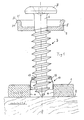
- Fig. 1 shows the fastening of a facade panel 1 to a slat substructure 2 by means of a screw 3, which can be a wood screw with a nail tip, a screw nail or another known self-drilling screw.
- a bore 4 is pre-drilled, which is larger in diameter than the outer diameter of the screw neck 6 lying in this fully assembled state in this bore 4, so that the facade panel 1 can expand unhindered relative to the substructure 2 and the screw 3.
- a washer 8 is captively attached below the screw head 7, the diameter of which is selected to be larger than the diameter of the bore 4.
- the outer edge 9 of this washer 8 is rounded, so that in the fully assembled state, in which the washer is firmly pressed onto the surface of the plate 1, the surface is not damaged by this edge during expansion.
- a centering ring 10 On the lower end of the screw 3, a centering ring 10 is placed, which has a cup-like shape and consists of an elastic plastic material.
- the thin-walled cup part 11 of the centering ring fits with free play in the bore 4 of the plate 1, the outer diameter of the cup part 11 is chosen so that there is little clearance between the cup part 11 and the bore wall.
- the cup part 11 merges into an upper guide section 12, which is slightly drawn radially inwards and ends in a threaded section 13 which corresponds approximately to the shape of the thread of the screw 3. About this section 13, the centering ring 10 is held on the thread of the screw 3 with a preferably tight fit.
- section 13 is only an annular collar projecting radially inward from the rim of the cup, in which the screw cuts itself automatically due to partial deformation of the elastic ring material, but this section 13 is preferably already designed in an injection molding process such that it matches the thread shape of screw 3 is adjusted so that the centering ring 10 can not only be easily screwed onto the screw like a nut, but also ensures that the centering ring can actually be placed and held concentrically with the screw axis.
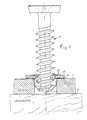
- a single thread with the pitch and shape of the screw thread is formed on the upper guide section 12; in the exemplary embodiment according to FIG. 2, the thread is formed by a plurality of knobs 14 formed on the inner circumference of the guide section 12 and projecting radially inward which correspond in shape and arrangement to the screw thread.
- either the plastic centering ring 10 is previously inserted into the bore 4 and then the Screw 3 screwed into the centering ring 10 until the screw tip grips in the substructure 2.
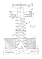
- Another possibility is to place the centering ring 10 on the screw 3 beforehand, for example in the preassembly position shown in FIG. 1. The fitter then only needs to insert the screw with the centering ring 10 attached to the tip into the bore and screw the screw into the substructure. Through the centering ring 10, the screw 3 is always guided exactly in the center of the bore 4 when it is being attached and also during screwing in, until the end position shown in FIG. 3 is reached, in which the washer 8 rests with pressure on the top of the plate 1.
- the axial height of the centering ring 10 is preferably chosen to be less than the thickness of the plate 1, so that the centering ring 10 is held loosely in the bore 4 in the final assembly position and there is a large distance on all sides in the radial direction between the inside of the cup part 11 and the screw shaft 6 exists, which enables an unimpeded radial displacement between facade panel and screw.
- Such a radial displacement is also not hindered by the guide section 12, because firstly the material of the centering ring is resilient and this guide section 12 has only a small axial height.
- the aforementioned formation of the threaded section 13 by distributed projecting knobs, through which the radial movement is even more unhindered, is particularly advantageous for this purpose.
- washer 8 is designed in a manner known per se as a pot-shaped pressed part, on the edge of which, after assembly, a plastic cover cap 15 can optionally be placed.
- FIG. 4 shows another form of the centering ring 10, here the underside is also drawn in radially inward in a funnel shape in order to facilitate insertion into the bore 4.
- the guide section 12, with which the centering ring 10 is held centrally on the screw 3 and which has the guide thread 13 on the inside, is additionally provided in FIG. 4 with an annular groove 16, into which, with snap action, a washer 18, which may also be 1 can again be designed as a cup part 8, can be used.
- the washer 18 is therefore first inserted into the guide section 12 in the groove 16 and is held there captively by the elastic material of the centering ring. If the unit consisting of centering ring 10 and attached washer 18 is now placed on the screw, the washer is also held together with the centering ring in a preassembly position. In this way, a simple, loss-proof preassembly of the washer on the screw is possible, which was previously only possible by simultaneously placing the washer and rolling the thread.
- the shape of the centering ring 10 can be of any type; if necessary, it can also be provided with additional cutouts, that is to say of a cage-like configuration, essentially is only that it reduces the space between screw 3 and bore 4 as little as possible in the fully assembled state so that this space remains fully available for radial movements, on the other hand the centering ring only has to be shaped and dimensioned so that it also has the desired centering effect assembly guaranteed.
- FIG. 5 shows a further possibility for the central insertion of a screw 3 into the bore 4 of a facade panel 1.
- This screw 3 has a thread 20, for example, again of a self-drilling type, the outer diameter 21 of which is chosen to be exactly as large or at most a few tenths of a millimeter smaller than the inner diameter of the bore 4 in the plate 1.
- the bore 4 has an inner diameter of 6.7 mm, for example, a screw 3 is used which has an outer thread diameter 21 of 6.5 mm.
- the drill tip is preferably relatively blunt so that the lower threads of the screw have their full outer diameter 21 as soon as possible immediately after the tip and can thus perform their guiding function right from the start when the screw is inserted into the bore 3.
- the outer diameter is so that the required play of, for example, 2.7 mm between screw neck 6 and bore 4 is ensured in the fully assembled state of the screw neck 6 is reduced by an additional machining operation to an outer diameter 23 of, for example, 4 mm.
- FIG. 6 shows the production of such a special screw according to FIG. 5.
- the starting point is a screw blank 25 with a wire diameter 26 (cylindrical outer diameter of the raw shaft part) of, for example, 5 mm.
- the neck section 6 below the screw head 7 is then on an axial length of at least the thickness of the facade panel 1 to a diameter 27 of, for example 4 mm reduced, that is, to a diameter that corresponds to the required later play of, for example, 2.7 mm in relation to the inner diameter of the bore 4 of the facade panel.
- the drill tip 22 is then produced and finally the thread 20 is rolled onto this blank screw by a known thread rolling process, which, starting from a pressing dimension of 5 mm, gives an outer diameter 21 of 6.5 mm, with a core diameter of approximately 3.6 to 4 mm.
- the drill tip 22 is preferably designed in a manner known per se so that, despite the larger outside diameter of the screw, it can easily be screwed into the substructure in the manner of a self-tapping screw.
- the exemplary embodiment according to FIG. 5 it is also advantageous for the exemplary embodiment according to FIG. 5 to additionally use a washer 8, the outer diameter of which is selected to be larger than the bore 4. It is also advantageous to fasten this washer 8 again captively to the screw 3. After this, the washer must be pushed onto the neck 6 of the screw before rolling the thread, the inner diameter 28 of the hole of the washer 8 must be at least as large as the diameter 26 of the screw blank, so that the washer 8 before the thread 20 is rolled on the screw shaft can be pushed on. In the example mentioned, the diameter of the hole 28 must therefore be at least 5 mm. However, this means that the washer 8 is no longer guided in the center of the screw neck, since this is only 4 mm in diameter due to its reduction.
- the corresponding design of the screw head 7 and the shape of this washer 8 ensure that the washer 8 is always exactly in the center of the screw head 7 due to the functional interaction of these parts and thus also leads to the screw shaft.
- a narrow annular shoulder could optionally be provided only on the underside of the screw head, the axial length of which is at most as large as the thickness of the washer 8 and which fills the hole 28 of the washer and thereby centers it.
- the washer 8 is always guided centrally to the screw and certainly covers the bore 4 of the plate 1 in accordance with regulations.
- the outer edge 9 of the washer 8 is rounded so that the surface of the facade panel 1 is not damaged when it is expanded and the expansion is possible without hindrance.
- the upper edge of the pot-shaped washer 8 is shaped radially outward to a protruding bead 32, the top 31 of which is rounded and without sharp edges. This prevents plastic from being scraped off the cover cap when the cover cap 15 is placed on it, and the annular groove 33 on the inside of the cover cap 15, which receives the edge bead 32 in the attached state, being damaged.
- the round upper side 31 thus ensures that the cap 15 is placed on the washer 8 with a good, long-lasting snap action and held there.
- the underside 34 of the bead 32 goes obliquely or with a certain curvature in the cylindrical outer wall of the cup-shaped washer 8 about.
- the cover cap 15 thus receives a certain pretension due to the interaction of this inclined surface 34 with the edge 35 of the annular groove 33 axially downward in the direction of the surface of the facade panel 1.
- the profile 36 of the cover cap 15 is otherwise largely adapted to the outer profile of the cup-shaped washer 8 in the sense of FIG. 3.
- the underside 37 of the cap 15 is undercut somewhat in the sense of FIG. 3, so that an elastic lip 38 is formed on the outer edge, which rests tightly on the upper side of the facade panel 1 due to the aforementioned axial compressive force.
- the axial dimension between the lip 38 and the lower edge 35 of the annular groove 33 is selected to be somewhat larger than the corresponding distance between the oblique underside 34 of the edge bead 32 and the underside the washer 8.
Landscapes
- Engineering & Computer Science (AREA)
- General Engineering & Computer Science (AREA)
- Mechanical Engineering (AREA)
- Architecture (AREA)
- Civil Engineering (AREA)
- Structural Engineering (AREA)
- Finishing Walls (AREA)
- Bolts, Nuts, And Washers (AREA)
- Connection Of Plates (AREA)
Applications Claiming Priority (2)
| Application Number | Priority Date | Filing Date | Title |
|---|---|---|---|
| DE19863639748 DE3639748C2 (de) | 1986-11-21 | 1986-11-21 | Schraube zum Befestigen von Fassadenplatten an einer Unterkonstruktion |
| DE3639748 | 1986-11-21 |
Publications (1)
| Publication Number | Publication Date |
|---|---|
| EP0271648A1 true EP0271648A1 (fr) | 1988-06-22 |
Family
ID=6314426
Family Applications (1)
| Application Number | Title | Priority Date | Filing Date |
|---|---|---|---|
| EP87113734A Withdrawn EP0271648A1 (fr) | 1986-11-21 | 1987-09-19 | Système pour fixer des plaques de façade à une sous-construction |
Country Status (2)
| Country | Link |
|---|---|
| EP (1) | EP0271648A1 (fr) |
| DE (1) | DE3639748C2 (fr) |
Cited By (5)
| Publication number | Priority date | Publication date | Assignee | Title |
|---|---|---|---|---|
| FR2647744A1 (fr) * | 1989-05-31 | 1990-12-07 | Perfiles Plasticos Navarra Sa | Plate-forme perfectionnee pour camions |
| EP1213497A1 (fr) * | 2000-12-07 | 2002-06-12 | Aoyama Seisakusho Co., Ltd. | Vis avec membre de retenue et d'étanchéité |
| WO2005011892A1 (fr) * | 2003-07-25 | 2005-02-10 | Textron Verbindungstechnik Gmbh & Co. Ohg | Vis presentant une rainure entre le filetage et la tete |
| EP2226518A3 (fr) * | 2009-03-05 | 2013-04-10 | TOGE-Dübel A. Gerhard KG | Dispositif de fixation |
| CN105378303A (zh) * | 2013-07-08 | 2016-03-02 | 株式会社托普拉 | 螺栓部件 |
Families Citing this family (4)
| Publication number | Priority date | Publication date | Assignee | Title |
|---|---|---|---|---|
| DE4033206A1 (de) * | 1990-01-24 | 1991-07-25 | Itw Ateco Gmbh | Selbstbohrschraube zum befestigen von holzteilen auf blechen |
| DE4116981A1 (de) * | 1991-05-24 | 1992-11-26 | Adolf Wuerth Gmbh & Co Kg | Schraube zum befestigen von gipskartonplatten |
| DE4239333A1 (de) * | 1992-11-23 | 1994-05-26 | Alfons Knoche | Schraube zum Befestigen von Fassadenplatten |
| CN111593614B (zh) * | 2020-05-21 | 2025-03-18 | 广东华工环源环保科技有限公司 | 纸浆模塑制品成型装置及其纸塑模具 |
Citations (11)
| Publication number | Priority date | Publication date | Assignee | Title |
|---|---|---|---|---|
| FR467794A (fr) * | 1913-02-24 | 1914-06-20 | Voigt Und Haeffner Ag | Procédé pour la fixation des rondelles sur les vis à filetage obtenu par refoulement |
| GB1151861A (en) * | 1965-04-15 | 1969-05-14 | George Kendrick Findlay | Improvements relating to the Fixing of Wall Claddings to Building Structures. |
| US3560132A (en) * | 1966-10-31 | 1971-02-02 | Deutsch Fastener Corp | Arrangement for captive screw |
| FR2086693A5 (fr) * | 1970-04-06 | 1971-12-31 | Derely Jean | |
| FR2121270A5 (fr) * | 1971-01-07 | 1972-08-18 | Barber Colman Co | |
| US3828493A (en) * | 1973-02-14 | 1974-08-13 | Robertson Co H H | Explosion pressures release fastener |
| FR2408751A1 (fr) * | 1977-11-15 | 1979-06-08 | Rivex Sa | Vis roulee a etrier cambre imperdable et son procede de fabrication |
| DE3043478A1 (de) * | 1980-02-12 | 1982-07-08 | Frank 5758 Fröndenberg Knoche | Selbstbohrende schraube |
| GB2142108A (en) * | 1983-06-22 | 1985-01-09 | Sfs Stadler Ag | Fastener for securing roofing sheeting over soft insulating material to a fixed support |
| DE8506297U1 (de) * | 1985-03-05 | 1985-06-27 | BWM Dübel- u. Montagetechnik GmbH, 7022 Leinfelden-Echterdingen | Befestigungselement |
| FR2578009A1 (fr) * | 1985-02-28 | 1986-08-29 | Gulistan Bulent | Organe de fixation de type captif notamment pour panneau |
Family Cites Families (3)
| Publication number | Priority date | Publication date | Assignee | Title |
|---|---|---|---|---|
| DE8021054U1 (de) * | 1980-10-30 | J.H. Benecke Gmbh, 3000 Hannover | Befestigungselement zur Halterung nachgiebiger, verformbarer Kunststoffplatten | |
| DE8108279U1 (de) * | 1981-03-20 | 1981-06-04 | Bierbach, Georg J., 5990 Altena | Abdeckkoppe für den kopf von mit einer Unterlegscheibe versehenen Schrauben zum Befestigen von Fassadenplatten |
| DE3423950A1 (de) * | 1984-06-29 | 1986-01-02 | Emil Rüsing GmbH & Co KG, 5608 Radevormwald | Platte, insbesondere fassadenverkleidungsplatte aus kunststoff |
-
1986
- 1986-11-21 DE DE19863639748 patent/DE3639748C2/de not_active Expired - Fee Related
-
1987
- 1987-09-19 EP EP87113734A patent/EP0271648A1/fr not_active Withdrawn
Patent Citations (11)
| Publication number | Priority date | Publication date | Assignee | Title |
|---|---|---|---|---|
| FR467794A (fr) * | 1913-02-24 | 1914-06-20 | Voigt Und Haeffner Ag | Procédé pour la fixation des rondelles sur les vis à filetage obtenu par refoulement |
| GB1151861A (en) * | 1965-04-15 | 1969-05-14 | George Kendrick Findlay | Improvements relating to the Fixing of Wall Claddings to Building Structures. |
| US3560132A (en) * | 1966-10-31 | 1971-02-02 | Deutsch Fastener Corp | Arrangement for captive screw |
| FR2086693A5 (fr) * | 1970-04-06 | 1971-12-31 | Derely Jean | |
| FR2121270A5 (fr) * | 1971-01-07 | 1972-08-18 | Barber Colman Co | |
| US3828493A (en) * | 1973-02-14 | 1974-08-13 | Robertson Co H H | Explosion pressures release fastener |
| FR2408751A1 (fr) * | 1977-11-15 | 1979-06-08 | Rivex Sa | Vis roulee a etrier cambre imperdable et son procede de fabrication |
| DE3043478A1 (de) * | 1980-02-12 | 1982-07-08 | Frank 5758 Fröndenberg Knoche | Selbstbohrende schraube |
| GB2142108A (en) * | 1983-06-22 | 1985-01-09 | Sfs Stadler Ag | Fastener for securing roofing sheeting over soft insulating material to a fixed support |
| FR2578009A1 (fr) * | 1985-02-28 | 1986-08-29 | Gulistan Bulent | Organe de fixation de type captif notamment pour panneau |
| DE8506297U1 (de) * | 1985-03-05 | 1985-06-27 | BWM Dübel- u. Montagetechnik GmbH, 7022 Leinfelden-Echterdingen | Befestigungselement |
Cited By (7)
| Publication number | Priority date | Publication date | Assignee | Title |
|---|---|---|---|---|
| FR2647744A1 (fr) * | 1989-05-31 | 1990-12-07 | Perfiles Plasticos Navarra Sa | Plate-forme perfectionnee pour camions |
| GB2234473A (en) * | 1989-05-31 | 1991-02-06 | Navarra Perfiles Plasticos | A platform for lorries |
| EP1213497A1 (fr) * | 2000-12-07 | 2002-06-12 | Aoyama Seisakusho Co., Ltd. | Vis avec membre de retenue et d'étanchéité |
| US6679666B2 (en) | 2000-12-07 | 2004-01-20 | Aoyama Seisakusho Co., Ltd. | Screw having a temporary holding member on the screw shank |
| WO2005011892A1 (fr) * | 2003-07-25 | 2005-02-10 | Textron Verbindungstechnik Gmbh & Co. Ohg | Vis presentant une rainure entre le filetage et la tete |
| EP2226518A3 (fr) * | 2009-03-05 | 2013-04-10 | TOGE-Dübel A. Gerhard KG | Dispositif de fixation |
| CN105378303A (zh) * | 2013-07-08 | 2016-03-02 | 株式会社托普拉 | 螺栓部件 |
Also Published As
| Publication number | Publication date |
|---|---|
| DE3639748A1 (de) | 1988-06-01 |
| DE3639748C2 (de) | 1997-06-05 |
Similar Documents
| Publication | Publication Date | Title |
|---|---|---|
| EP0742873B1 (fr) | Unite de montage comprenant une partie de montage, une partie de fixation et un manchon faisant office de securite anti-desserrage, et procede de production de ladite unite de montage | |
| DE3309320C2 (fr) | ||
| EP1229257B1 (fr) | Dispositif d'assemblage constitué par une pièce à assembler et au moins une vis | |
| EP1690013B1 (fr) | Element fonctionnel, composant d'assemblage compose de l'element fonctionnel combine a une tole, procede de fabrication du composant d'assemblage et procede de fabrication de l'element fonctionnel | |
| EP2229538B1 (fr) | Élément de fixation et son procédé de fixage | |
| DE19902461A1 (de) | Mutter mit T-förmigem Querschnitt | |
| EP0307647A1 (fr) | Rondelle | |
| EP3707396B1 (fr) | Dispositif anti-détachement pour vis et unité de montage | |
| DE8512712U1 (de) | Schraube | |
| EP1205676B1 (fr) | Unité de montage constituée d'un composant et d'au moins une vis | |
| DE69501636T2 (de) | Einsatzmutter und Befestigungselement | |
| EP1117882B1 (fr) | Element de fixation et procede pour fixer des bandes ou des plaques isolantes sur une base fixe | |
| DE8606197U1 (de) | Selbstschneidende Schraube | |
| DE3120132A1 (de) | Befestigungselement | |
| DE1500792A1 (de) | Gewindebefestigungsanordnung | |
| EP0171745A1 (fr) | Dispositif de fixation consistant en une cheville d'écartement en matière plastique et une vis de fixation | |
| DE2925526A1 (de) | Befestigungselement und zugehoeriges werkzeug | |
| EP0319812A1 (fr) | Vis autoforante | |
| EP3199824A1 (fr) | Système de fixation et son utilisation | |
| DE3639748C2 (de) | Schraube zum Befestigen von Fassadenplatten an einer Unterkonstruktion | |
| DE69202387T2 (de) | Verfahren zur Herstellung einer Selbstbohrschraube. | |
| DE2620272A1 (de) | Zusammengesetztes befestigungsmittel | |
| WO1988009708A1 (fr) | Outil de vissage et vis utilisables avec cet outil | |
| EP1004782B1 (fr) | Boulon moleté | |
| DE102004031342A1 (de) | Befestigungsanordnung für eine Verkleidung und Befestigungsverfahren |
Legal Events
| Date | Code | Title | Description |
|---|---|---|---|
| PUAI | Public reference made under article 153(3) epc to a published international application that has entered the european phase |
Free format text: ORIGINAL CODE: 0009012 |
|
| AK | Designated contracting states |
Kind code of ref document: A1 Designated state(s): AT BE CH DE ES FR GB GR IT LI LU NL SE |
|
| 17P | Request for examination filed |
Effective date: 19880525 |
|
| 17Q | First examination report despatched |
Effective date: 19890913 |
|
| STAA | Information on the status of an ep patent application or granted ep patent |
Free format text: STATUS: THE APPLICATION IS DEEMED TO BE WITHDRAWN |
|
| 18D | Application deemed to be withdrawn |
Effective date: 19900124 |