EP0272070B1 - Eingabevorrichtung für einen Rechner - Google Patents
Eingabevorrichtung für einen Rechner Download PDFInfo
- Publication number
- EP0272070B1 EP0272070B1 EP87310981A EP87310981A EP0272070B1 EP 0272070 B1 EP0272070 B1 EP 0272070B1 EP 87310981 A EP87310981 A EP 87310981A EP 87310981 A EP87310981 A EP 87310981A EP 0272070 B1 EP0272070 B1 EP 0272070B1
- Authority
- EP
- European Patent Office
- Prior art keywords
- area
- key code
- registration
- visible information
- computer
- Prior art date
- Legal status (The legal status is an assumption and is not a legal conclusion. Google has not performed a legal analysis and makes no representation as to the accuracy of the status listed.)
- Expired - Lifetime
Links
Images


Classifications
-
- G—PHYSICS
- G06—COMPUTING OR CALCULATING; COUNTING
- G06F—ELECTRIC DIGITAL DATA PROCESSING
- G06F3/00—Input arrangements for transferring data to be processed into a form capable of being handled by the computer; Output arrangements for transferring data from processing unit to output unit, e.g. interface arrangements
- G06F3/01—Input arrangements or combined input and output arrangements for interaction between user and computer
- G06F3/02—Input arrangements using manually operated switches, e.g. using keyboards or dials
- G06F3/0202—Constructional details or processes of manufacture of the input device
- G06F3/021—Arrangements integrating additional peripherals in a keyboard, e.g. card or barcode reader, optical scanner
Definitions
- the present invention relates to an input apparatus used to input desired data to a computer.
- a keyboard for inputting data be sequentially operating a plurality of keys arranged.
- a digitizer of the type to input data by allowing a stylus pen to come into contact with the upper surface of a tablet a touch panel of the type to input data by allowing a light pen or a finger to directly come into contact with the surface of a CRT screen, a mouse of the type to input data by rotating balls or the like on a desk, a bar code reader of the type to input data by scanning bar codes with use of a light pen, and the like.
- Embodiments of the present invention aim to provide an input apparatus for a computer which can be applied to a computer having no special software and which is excellent in operating efficiency.
- the present invention as defined in claim 1 therefore provides an input apparatus for a computer having an area designating means on which a visible information sheet (S1-S3) having predetermined visible information is locatable and which is adapted to output an area designation signal indicative of a designated region of said visible information sheet, wherein said input apparatus is connectable between a computer and a keyboard having a plurality of keys provided thereon; and said input apparatus further comprises: switch means for selecting a registration mode or an input mode; receiving means which is enabled when the registration mode is selected by the switch means, for receiving a key code representing one or a plurality of keys provided on said keyboard, to which said designated area is to correspond, said key code being outputted from said keyboard; registration means which is enabled when the registration mode is selected by the switch means, for storing area data representing the designated area indicated by an area designation signal outputted from said area designating means and the key code received by said receiving means to which the designated area corresponds; data fetching means, which is enabled when the input mode is selected by the switch means, for retrieving the corresponding key code from
- the operator When registering, the operator designates a desired area on the visible information sheet put on the area designating means and also inputs a key code of one or a plurality of series of keys by the keyboard.
- the input key code signal is received by the receiving means.
- This key code and the designated area of the visible information are registered as mutually corresponding data into the registering means.
- the registering operations and processes are repeatedly executed for a desired number of areas on the visible information sheet.
- the operator can execute the input operations and processes using the input apparatus according to the invention. Namely, the operator designates the area of a desired visible information on the visible information sheet by use of the area designating means. Thus, the key code corresponding to the designated area is taken out of the registering means and transmitted to the computer through the transmitting means.
- the signal transmitted through the interface of a computer is the key code which is the same as the key code input from the keyboard. Therefore, the invention can be used for all of the computers having the software capable of processing the key code signal from the keyboard. Moreover, the easiness and simplicity in operation can be improved.
- the visible information sheet having the visible information Prior to using the foregoing input apparatus for computers, the visible information sheet having the visible information is set to the input apparatus.
- the operation to designate a desired area of the visible information and the operation of the keyboard are performed in parallel, thereby producing the registration data in which the key code is- made correspond to each designated area.
- This registration data is previously registered into the registering means in the input apparatus. Therefore, after completion of the data registration, by designating a desired area on the visible information sheet, the corresponding key code can be taken out of the registering means and transmitted to the computer.
- embodiments of the present invention provide an input apparatus for computers in which the complicated registering work is eliminated by enabling the registration data to be fed from an external system, a computer for example.
- an input apparatus for a computer as defined in claim 2 having an area designating means on which a visible information sheet (S1-S3) having predetermined visible information is locatable and which is adapted to output an area designation signal indicative of a designated region of said visible information sheet, wherein said input apparatus is connectable to a computer, an external apparatus and a keyboard having a plurality of keys provided thereon; and said input apparatus further comprises: switch means for selecting a registration mode or an input mode; receiving means which is enabled when the registration mode is selected by the switch means for receiving registration data comprising area data indicating a region of the visible information sheet and a key code representing one or a plurality of keys provided on said keyboard to which said designated area is to correspond, the registration data being received from said external apparatus; registration means which is enabled when the registration mode is selected by the switch means, for storing the registration data received by said receiving means, data fetching means which is enabled when the input mode is selected by the switch means for retrieving the corresponding key code from said registration means in response to an area designation signal
- the registration data comprising the area of the visible information on the visible information sheet and the key code corresponding to the area is received from an external system and stored into the memory means.
- the area of desired visible information is designated by the area designating means.
- the key code corresponding to the designated area is taken out of the memory means and transmitted to the computer by the transmitting means.
- the input operations are made easy and simplified and the complicated registering works can be eliminated.
- Fig. 1 shows an external view of an input apparatus 1 for computers according to an embodiment of the present invention.
- the input apparatus 1 for computers is connected between a keyboard 2 and a computer 3.
- the input apparatus 1 has a pad portion 4 on which a visible information sheet is attachably and detachably set and an operating section 5 in which various kinds of switches regarding the registering and transmitting operations and the like are arranged.
- the pad portion 4 detects the point at which the operator depressed the surface of the visible information sheet and outputs a signal indicative of the position (X and Y coordinates) of the depressed point.
- the pad portion 4 has a concave portion 7 into which a transparent holder 6 is positioned.
- the visible information sheet is inserted into the transparent holder 6.
- the pad portion 4 also has a clip 8 to hold the transparent holder 6 in the concave portion 7.
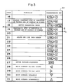
- the visible information relative to the keys on the keyboard 2 is written on the visible information sheet. Practical examples of the visible information sheets are illustrated in Figs. 3 to 5.
- the visible information sheet S1 shown in Fig. 3 shows the operating method of the keyboard 2 by a table in which the functions of the computer and the kinds of keys which are operated to realize the functions are shown so as to correspond to each other.
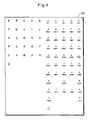
- the visible information sheet S2 shown in Fig. 4 shows alphabets in accordance with the alphabetical order of A, B, C, ... and also shows Japanese KATAKANA characters in accordance with the order of the KATAKANA syllabary in a manner such that these alphabets and KATAKANA characters are arranged on one plane.
- the key code signals which equivalently indicate that the keys of these characters on the keyboard 2 were depressed are given to the computer 3 from the input apparatus 1.
- a visible information sheet S3 shown in Fig. 5 the name of the users and the codes of the users are correspondingly shown.
- the sheet S3 is put on the pad portion 4 and the area in which a user's name is written is depressed. In this manner, the operator can input the user's code.
- the operating section 5 is operated by the operator to perform the registering and inputting operations.
- the operating section 5 has: a change-over switch 9; a sheet selecting switch 10; a registration-end switch 11; a corresponding switch 12; and a display 14 to display the sheet number or various kinds of messages.
- the switch 10, 11 and 12 constitute a switch growth 13.
- the switch 9 is used to select either the registering mode or the inputting mode.
- the switch 10 is used to select the number of visible information sheet which is set to the pad portion 4.
- the switch 11 is used to indicate the end of registering operation.
- the switch 12 is used to instruct the correspondence between the area of the visible information on the visible information sheet and the key code which is input by the keyboard 2.
- Fig. 2 shows an example of a circuit constitution of the input apparatus 1.
- switch group 13 and display 14 a key code receiver 16, key code transmitter 17, and registering memory 18 are connected to a CPU 15.
- the key code receiver 16 receives a key code signal sent from the keyboard 2.
- the key code read out from the registering memory 18 and the key code sent from the keyboard 2 are transmitted to the computer 3 by the transmitter 17.
- the CPU 15 controls the input and output of the pad portion 4, switch group 13, display 14, key code receiver 16 and key code transmitter 17. While the CPU 15 reads or writes data from or into the registering memory 18, the CPU 15 executes various kinds of arithmetic operations and processes by use of various functions regarding the registration processing and transmission (input processing).
- the CPU 15 has the following functions and the like with respect to the registration.
- the CPU 15 has the following functions and the like with respect to the transmission (input processing).
- the sheet numbers assigned to the visible information sheets S1, S2, S3, ... are stored into a sheet number memory 21 in the registering memory 18. Each of the sheet numbers is also made correspond to each area which is stored into the area memory 19.
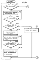
- Figs. 6a and 6b show the flows of the registering and inputting processings in the input apparatus 1.
- step 1 (hereinafter, abbreviated to "ST1") in Fig. 6a is "YES”.
- ST2 the apparatus waits for the input of a depressed point to define the area.
- the answer in ST3 is "YES" and the positions of the depressed points are detected by the pad portion 4.
- the CPU 15 sets a rectangular area a (indicated by bold lines in Fig. 3) which is specified by these depressed points as an area to be defined.
- the CPU 15 refers to the area memory 19 in the registering memory 18 and checks to see if this defining area overlaps the area which has already been defined or not. If it is determined that they overlap (“YES" in ST4), ST9 follows and the CPU 15 displays an error message by the display 14.
- the CPU 15 stores the defining area into the area memory 19 in the registering memory 18 and thereafter, the apparatus waits until the key code train corresponding to the defining area is received by the key code receiver 16 (ST5 and ST6).
- the key code train is received by the key code receiver 16.
- the answer in ST7 is "YES”.
- the CPU 15 defines the key code train regarding the reception as one word and stores this word into the word memory 20 in correspondence to the defining area (ST8).
- All of the areas on the visible information sheets S1 are sequentially defined by repeating the above operation.
- the operator depresses the registration-end switch 11.
- the CPU 15 gives the sheet number to the visible information sheet S1.
- This sheet number is stored into the sheet number memory 21 and also displayed by the display 14.
- the operator confirms the display content and writes the sheet number to a proper position on the sheet S1. Thereafter, the sheet S1 is exchanged to another visible information sheet and the similar operations are repeatedly executed.
- the holder 6 After the sheet S1 of the selected sheet number was inserted into the transparent holder 6, the holder 6 is set to the pad portion 4.
- the CPU 15 determines whether the area including the depressed point exists as the defining area or not (ST11) by referring to the content of the area memory 19. If the defining area exists, the answer in ST11 is "YES”. In ST12, the CPU 15 then reads out the key code train (in this case, the key code train regarding the "CTRL” and "S" keys) corresponding to the defining area from the word memory 20 and sends to the computer 3 from the key code transmitter 17.
- the program as the function of this command is executed and the temporary stop of the execution of program or the display on the screen is executed in the computer 3.
- the user can originally make his own visible information sheet and input desired data by use of this sheet. Therefore, the input apparatus for computers which can be remarkably easily used can be realized.
- Figs. 7 and 8 show the improved input apparatus.
- the same or similar parts and components as those shown in Figs. 1 and 2 are designated by the same reference numerals.
- the mode change-over switch 9 and sheet selecting switch 10 constitute the switch group 13.
- the other switches 11, 12 and the like are not provided.
- the switch 9 is used to make the pad portion 4 operative or inoperative.
- the sheet selecting switch 10 is used to select the number of visible information sheet which is set to the pad portion 4.
- a block indicated at numeral 17 is named as a transmitter/receiver.
- the transmitter/receiver 17 has the functions to transmit the key code read out from the registering memory 18 and the key code sent from the keyboard 2 to the computer 3 and to receive the registration data and other data from the computer 3 and other external systems.
- the registration data comprises area of the visible information on the visible information sheet and a predetermined key code train (including one key code) corresponding to this area.
- a predetermined key code train including one key code
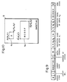
- Fig. 9 shows an example of a constitution of the registration data with respect to a visible information sheet S shown in Fig. 10.
- the sheet S of Fig. 10 includes two visible information areas a1 and a2.
- the area a1 is defined by the corner point P1 which is specified by coordinates (X1, Y1) and the corner point P2 which is specified by coordinates (X2, Y2).
- the key code train "A" corresponds to the area a1.
- the other area a2 is defined by a corner point P1′ which is specified by coordinates (X1′, Y1′) and a corner point P2′ which is specified by coordinates (X2′, Y2′).
- the key code train "BCDEF" corresponds to the area a2.
- this data includes: a start code (symbol); a sheet number, a sheet name, number of areas, length of data, defining data of the areas a1 and a2 (comprising the coordinates data of each corner point, length of key code (train) and key code (train)); and an end code (symbol).
- the CPU 15 controls the input and output operations and processing of the pad portion 4, switch group 13, display 14, key code receiver 16 and transmitter/receiver 17. While the CPU 15 reads or writes data from or into the registering memory 18, it executes various kinds of arithmetic operations and processes by use of various functions regarding the registration and transmission/reception.
- the CPU 15 has the following functions and the like with respect to the registration processing.
- the CPU 15 has the following functions and the like with respect to the transmission processing.
- a registering program is activated using an external apparatus, e.g., the keyboard 2 and computer 3.
- Fig. 13 shows a registering processing procedure by the computer 3.
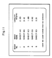
- a table of sheets as shown in Fig. 11 is displayed by the display of the computer 3.
- This table includes five kinds of registration data of the sheet numbers 1 to 5. The sheet name and memory capacity of each registration data is together shown in this table.
- the computer 3 enters the standby mode to wait for the transmission of a key code from the keyboard 2 (ST22).
- the operator looks at the content on the display screen and selects a desired registration data and inputs the relevant sheet number by operating the keyboard 2. If the desired registration data is not displayed on the screen, the display content on the screen is scrolled until the registration data whose sheet number is 6 or more is displayed on the display (ST24 and ST25).
- the answer in ST23 is "YES".
- the key code of this sheet number is transmitted to the computer 3 through the input apparatus 1.
- the computer 3 sends the registration data corresponding to the sheet number designated to the input apparatus 1 on the basis of the data format shown in Fig. 12 (ST26).
- Fig. 14 shows a registering procedure of the registration data in the input apparatus 1.
- the CPU 15 takes into the reception data from the transmitter/receiver 17 and reads out the sheet number. Further, the CPU 15 refers to the sheet number memory 21 in the registering memory 18 and determines whether the registration data of the sheet number received has already been registered or not (ST41 and ST42).
- the CPU 15 stores the sheet number of the registration data, area data and key code train into the sheet number memory 21, area memory 19 and key code train memory 20 in the registering memory 18 so as to correspond to each other. Then, the sheet number is displayed by the display 14 (ST46, ST47).
- the CPU 15 produces a command to inquire whether or not the registration data which had already been registered may be replaced by the registration data which has just been received. This command is sent to the computer 3 through the transmitter/receiver 17 (ST43).
- the computer 3 In response to the inquiry command, the computer 3 displays a message to inquire whether the registration data may be replaced or not by the display. Then, the computer 3 waits for an instruction which is input by the key operation by the operator (ST28 in Fig. 13).
- the operator wants to instruct the replacement of the registration data, the operator operates the keys on the keyboard 2 in accordance with this instruction. In this case, the answer in ST29 is "YES" and the command to instruct the replacement of the registration data is given to the input apparatus 1 (ST30). If the operator operates the key to inhibit the replacement of the registration data, the answer in ST29 is "NO", so that a command to inhibit the replacement of the registration data is given to the input apparatus 1 (ST31).
- the foregoing command is received by the key code receiver 16 in the input apparatus 1 (ST44 in Fig. 14). If this command is the command to instruct the replacement of the registration data, the answer in ST45 is "YES”. The registration data is stored into the registering memory 18 in ST46. The sheet number is displayed by the display 14 in ST47 and thereafter, the end of registration command is sent to the computer 3 from the transmitter/receiver (ST48).
- the sheet number is displayed on the display 14.
- the operator looks at the display content on the screen and depresses the sheet selecting switch 10 to change the sheet number, thereby selecting the desired visible information sheet (for example, S1) to by used now.
- the visible information sheet S1 of the sheet number is inserted into the holder 6. Then, the holder is set to the pad portion 4.
- the operator depresses an arbitrary position in the area a on the visible information sheet S1 by the finger.
- the CPU 15 refers to the registering memory 18 and reads out the key code train (in this case, the key code train regarding the "CTRL" and "S" keys) corresponding to the area a from the key code train memory 20 and sends this key code train from the transmitter/receiver 17 to the computer 3 in a manner similar to the foregoing embodiment.
- the computer 3 temporarily stops executed program or the display on the screen in accordance with the function of the relevant command.
- the registration data can be fetched from an external system. Therefore, if the registration data has preliminarily been made, by merely transferring the registration data from the external system, it can be easily registered. There is no need to perform the complicated work to "register" before the input apparatus is used. On the other hand, since the registration data can be held in an external medium, a number of visible information sheets in excess of the capacity of the registering memory can be used.
Landscapes
- Engineering & Computer Science (AREA)
- General Engineering & Computer Science (AREA)
- Theoretical Computer Science (AREA)
- Human Computer Interaction (AREA)
- Physics & Mathematics (AREA)
- General Physics & Mathematics (AREA)
- Input From Keyboards Or The Like (AREA)
Claims (3)
- Eingabevorrichtung (1) für einen Computer mit (einem) Flächenzuordnungsmittel(n) (4), auf dem bzw. denen ein sichtbares Informationsblatt (S₁-S₃) mit vorgegebener sichtbarer Information angebracht werden kann und das ausgebildet ist, um ein Flächenzuordnungssignal, das für einen zugeordneten Bereich des sichtbaren Informationsblattes bezeichnend ist, auszugeben,
dadurch gekennzeichnet, daß:
die Eingabevorrichtung zwischen bzw. mit einem Computer (3) und einer Tastatur (2) mit einer Vielzahl an darauf vorgesehenen Tasten (an)schaltbar bzw. verbindbar ist; und
daß die Eingabevorrichtung weiters umfaßt:
Schaltmittel (9) zum Auswählen eines Registrierungsmodus oder eines Eingabemodus;
Empfangsmittel (15,16), das bzw. die freigegeben bzw. eingeschaltet ist bzw. sind, wenn der Registrierungsmodus durch die Schaltmittel ausgewählt ist, um einen Tastencode zu empfangen, der eine oder eine Vielzahl der auf der Tastatur vorgesehenen Tasten repräsentiert, mit dem die zugeordnete Fläche korrespondieren soll, wobei der Tastencode von der Tastatur ausgegeben wird;
Registrierungsmittel (15,18), das bzw. die freigegeben bzw. eingeschaltet ist bzw. sind, wenn der Registrierungsmodus durch die Schaltmittel ausgewählt ist, um Flächendaten zu speichern, die die zugeordnete Fläche repräsentieren, bezeichnet durch ein Flächenzuordnungssignal, das von dem bzw. den Flächenzuordnungsmittel(n) ausgegeben wird und den von dem bzw. den Empfangsmittel(n) empfangenen Tastencode, mit dem die zugeordnete Fläche korrespondiert;
Datenholmittel (15), das bzw. die freigegeben bzw. eingeschaltet ist bzw. sind, wenn der Eingabemodus durch die Schaltmittel ausgewählt ist, um den korrespondierenden Tastencode von den Registrierungsmitteln als Antwort auf ein Flächenzuordnungssignal, das von den Flächenzuordnungsmitteln ausgegeben wurde, wiederzugewinnen, und
Sendemittel (17), das bzw. die freigegeben bzw. eingeschaltet ist bzw. sind, wenn der Eingabemodus durch die Schaltmittel ausgewählt ist, um den wiedergewonnenen Tastencode an den Computer zu senden. - Eingabevorrichtung (1) für einen Computer mit (einem) Flächenzuordnungsmittel(n) (4), auf dem bzw. denen ein sichtbares Informationsblatt (S₁-S₃) mit vorgegebener sichtbarer Information angebracht werden kann und das ausgebildet ist, um ein Flächenzuordnungssignal, das für einen zugeordneten Bereich des sichtbaren Informationsblattes bezeichnend ist, auszugeben,
dadurch gekennzeichnet, daß:
die Eingabevorrichtung an einen Computer (3), eine externe Vorrichtung (3) und eine Tastatur (2) mit einer Vielzahl an darauf vorgesehenen Tasten anschaltbar ist; und
daß die Eingabevorrichtung weiters umfaßt:
Schaltmittel (9) zum Auswählen eines Registrierungsmodus oder eines Eingabemodus;
Empfangsmittel (15,17), das bzw. die freigegeben bzw. eingeschaltet ist bzw. sind, wenn der Registrierungsmodus durch die Schaltmittel ausgewählt ist, um Registrierungsdaten zu empfangen, umfassend Flächendaten, die einen Bereich des sichtbaren Informationsblattes bezeichnen, und einen Tastencode, der eine oder eine Vielzahl der auf der Tastatur vorgesehenen Tasten repräsentiert, mit dem die zugeordnete Fläche korrespondieren soll, wobei die Registrierungsdaten von der externen Vorrichtung empfangen werden;
Registrierungsmittel (15,18), das bzw. die freigegeben bzw. eingeschaltet ist bzw. sind, wenn der Registrierungsmodus durch die Schaltmittel ausgewählt ist, um die von dem bzw. den Empfangsmittel(n) empfangenen Registrierungsdaten zu speichern,
Datenholmittel (15), das bzw. die freigegeben bzw. eingeschaltet ist bzw. sind, wenn der Eingabemodus durch die Schaltmittel ausgewählt ist, um den korrespondierenden Tastencode von dem bzw. den Registrierungsmittel(n) als Antwort auf ein Flächenzuordnungssignal, das von dem bzw. den Flächenzuordnungsmittel(n) ausgegeben wurde, wiederzugewinnen, und
Sendemittel (17), das bzw. die freigegeben bzw. eingeschaltet ist bzw. sind, wenn der Eingabemodus durch die Schaltmittel ausgewählt ist, um den wiedergewonnenen Tastencode an den Computer zu senden. - Vorrichtung nach Anspruch 1 oder 2, worin das Registrierungsmittel (18) einen ersten Speicherteil (19) zum Speichern von für die Fläche der sichtbaren Information bezeichnenden Daten und einen zweiten Speicherteil (20) zum Speichern des mit der Fläche der sichtbaren Information korrespondierenden Tastencodes umfaßt.
Applications Claiming Priority (4)
| Application Number | Priority Date | Filing Date | Title |
|---|---|---|---|
| JP298164/86 | 1986-12-15 | ||
| JP61298164A JPS63149718A (ja) | 1986-12-15 | 1986-12-15 | コンピユ−タ入力装置 |
| JP61300626A JPS63153621A (ja) | 1986-12-17 | 1986-12-17 | コンピユ−タ入力装置 |
| JP300626/86 | 1986-12-17 |
Publications (3)
| Publication Number | Publication Date |
|---|---|
| EP0272070A2 EP0272070A2 (de) | 1988-06-22 |
| EP0272070A3 EP0272070A3 (en) | 1989-11-29 |
| EP0272070B1 true EP0272070B1 (de) | 1995-03-01 |
Family
ID=26561402
Family Applications (1)
| Application Number | Title | Priority Date | Filing Date |
|---|---|---|---|
| EP87310981A Expired - Lifetime EP0272070B1 (de) | 1986-12-15 | 1987-12-14 | Eingabevorrichtung für einen Rechner |
Country Status (2)
| Country | Link |
|---|---|
| US (1) | US4916740A (de) |
| EP (1) | EP0272070B1 (de) |
Families Citing this family (20)
| Publication number | Priority date | Publication date | Assignee | Title |
|---|---|---|---|---|
| DE3920429A1 (de) * | 1989-06-22 | 1991-01-10 | Pfaff Haushaltmasch | Digitalisiergeraet |
| AU6290490A (en) * | 1989-09-07 | 1991-04-08 | Enno Messerschmitt | Input-output media for the input of data using an input device |
| JPH0666048B2 (ja) * | 1989-10-06 | 1994-08-24 | 富士ゼロックス株式会社 | 操作手順一括登録装置 |
| DE69125741T2 (de) * | 1990-02-20 | 1997-10-02 | Canon Kk | Faksimilegerät |
| DE69131496T2 (de) * | 1990-05-15 | 2000-01-05 | Canon K.K., Tokio/Tokyo | Bildverarbeitungs-Gerät und Verfahren |
| US5265029A (en) * | 1990-08-20 | 1993-11-23 | Chemical Concepts Corporation | Chemical calculator |
| US6225983B1 (en) * | 1990-10-11 | 2001-05-01 | Fuji Xerox Co., Ltd | Operation key registration system for a coordinate input device |
| EP0549956B1 (de) * | 1991-12-26 | 1998-03-18 | Seiko Instruments Inc. | Koordinatenablesesystem zur Detektion der Betriebszustände von zahlreichen Schaltern |
| IL103062A (en) * | 1992-09-04 | 1996-08-04 | Algorithmic Res Ltd | Data processor security system |
| US5450078A (en) * | 1992-10-08 | 1995-09-12 | Intellitools, Inc. | Membrane computer keyboard and method |
| US5627349A (en) * | 1993-07-01 | 1997-05-06 | Integral Information Systems | Interactive data entry apparatus |
| US5444192A (en) * | 1993-07-01 | 1995-08-22 | Integral Information Systems | Interactive data entry apparatus |
| US5613137A (en) * | 1994-03-18 | 1997-03-18 | International Business Machines Corporation | Computer system with touchpad support in operating system |
| US5559512A (en) * | 1995-03-20 | 1996-09-24 | Venturedyne, Ltd. | Method and apparatus for entering alpha-numeric data |
| US6018335A (en) * | 1997-08-19 | 2000-01-25 | Kdi Precision Products, Inc. | Programmable keyboard and method therefor |
| US6037928A (en) | 1997-11-13 | 2000-03-14 | Imageworks Manufacturing, Inc. | System and method for providing restrained, streamlined access to a computerized information source |
| US6337678B1 (en) | 1999-07-21 | 2002-01-08 | Tactiva Incorporated | Force feedback computer input and output device with coordinated haptic elements |
| US6700773B1 (en) * | 2000-11-03 | 2004-03-02 | Revolutionary Learning Systems, Inc. | Method and apparatus for implementing a configurable personal computing device |
| TWM267499U (en) * | 2004-12-01 | 2005-06-11 | Tatung Co | Incline structure using for a monitor |
| DE112009001503T5 (de) | 2008-06-20 | 2011-04-28 | Mattel, Inc., El Segundo | Kapazitives Tastfeld und Spielzeug, das ein solches enthält |
Family Cites Families (6)
| Publication number | Priority date | Publication date | Assignee | Title |
|---|---|---|---|---|
| JPS5533104B2 (de) * | 1973-01-22 | 1980-08-28 | ||
| US4385366A (en) * | 1980-09-02 | 1983-05-24 | Texas Instruments Incorporated | Programmable device using selectively connectable memory module to simultaneously define the functional capability and the display associated with input switches |
| EP0155409A1 (de) * | 1984-03-19 | 1985-09-25 | Luigi Langella | System zur automatischen Herstellung von graphischen Musikoriginalen |
| DE3586927T2 (de) * | 1984-04-20 | 1993-06-03 | Hitachi Ltd | Flaches bildschirmanzeigesystem mit integriertem eingabegeraet. |
| US4763252A (en) * | 1985-03-21 | 1988-08-09 | Rose David K | Computer entry system for predetermined text data sequences |
| US4716542A (en) * | 1985-09-26 | 1987-12-29 | Timberline Software Corporation | Method and apparatus for single source entry of analog and digital data into a computer |
-
1987
- 1987-12-14 EP EP87310981A patent/EP0272070B1/de not_active Expired - Lifetime
-
1989
- 1989-06-02 US US07/361,716 patent/US4916740A/en not_active Expired - Fee Related
Also Published As
| Publication number | Publication date |
|---|---|
| EP0272070A2 (de) | 1988-06-22 |
| EP0272070A3 (en) | 1989-11-29 |
| US4916740A (en) | 1990-04-10 |
Similar Documents
| Publication | Publication Date | Title |
|---|---|---|
| EP0272070B1 (de) | Eingabevorrichtung für einen Rechner | |
| CA2007411C (en) | Advanced user interface | |
| JP4577933B2 (ja) | コンピュータ切替器 | |
| US4881064A (en) | Information processor having cursor display system and control | |
| EP0243925B1 (de) | Befehlseingabesystem für einen elektronischen Rechner | |
| EP0538705A1 (de) | Graphische Benutzerschnittstelle mit Gestenerkennung in einer Umgebung mit mehreren Anwendungsprogrammen | |
| US5734377A (en) | Data matching method, coordinate input method, and coordinate input system | |
| KR880000251B1 (ko) | 도형 처리방법 | |
| EP0089132A1 (de) | Verfahren und Vorrichtung zum Setzen einer Informationseingangszone bei einem Koordinateneingabegerät | |
| JP4077959B2 (ja) | 文字処理装置及びその方法、及びそのプログラムを記憶した記憶媒体 | |
| JPH0594564A (ja) | データ処理システム | |
| JP2000148334A (ja) | 文字処理装置及びその方法、及びそのプログラムを記憶した記憶媒体 | |
| JPH09247338A (ja) | 画像処理装置並びに情報処理装置並びに画像処理システムおよび画像処理システムのデータ処理方法およびコンピュータで読出し可能なプログラムを格納した記憶媒体 | |
| JP2500283B2 (ja) | 仮想空間キ―ボ―ド装置 | |
| EP0367290A2 (de) | Steuerverfahren für Cursorbewegung und Vorrichtung zu deren Ausführung | |
| JP2970743B2 (ja) | データ通信装置 | |
| JP3720411B2 (ja) | 文書処理装置 | |
| JPH0610423Y2 (ja) | コンピユ−タ入力装置 | |
| JPH09258873A (ja) | 入力装置 | |
| JPH0736608A (ja) | 画面表示情報の選択システムおよびその選択方法 | |
| JPH01280853A (ja) | 端末コンピユータ | |
| JPS63149718A (ja) | コンピユ−タ入力装置 | |
| JPH06202846A (ja) | 言語入力システムおよび方法 | |
| JPS63153621A (ja) | コンピユ−タ入力装置 | |
| JP2002268800A (ja) | 電子機器、電子機器の制御方法、および電子機器の制御プログラム |
Legal Events
| Date | Code | Title | Description |
|---|---|---|---|
| PUAI | Public reference made under article 153(3) epc to a published international application that has entered the european phase |
Free format text: ORIGINAL CODE: 0009012 |
|
| 17P | Request for examination filed |
Effective date: 19880130 |
|
| AK | Designated contracting states |
Kind code of ref document: A2 Designated state(s): AT BE CH DE ES FR GB GR IT LI LU NL SE |
|
| PUAL | Search report despatched |
Free format text: ORIGINAL CODE: 0009013 |
|
| AK | Designated contracting states |
Kind code of ref document: A3 Designated state(s): AT BE CH DE ES FR GB GR IT LI LU NL SE |
|
| 17Q | First examination report despatched |
Effective date: 19920115 |
|
| RAP1 | Party data changed (applicant data changed or rights of an application transferred) |
Owner name: OMRON CORPORATION |
|
| GRAA | (expected) grant |
Free format text: ORIGINAL CODE: 0009210 |
|
| RBV | Designated contracting states (corrected) |
Designated state(s): GB |
|
| AK | Designated contracting states |
Kind code of ref document: B1 Designated state(s): GB |
|
| REG | Reference to a national code |
Ref country code: DE Ref legal event code: 8566 |
|
| PLBE | No opposition filed within time limit |
Free format text: ORIGINAL CODE: 0009261 |
|
| STAA | Information on the status of an ep patent application or granted ep patent |
Free format text: STATUS: NO OPPOSITION FILED WITHIN TIME LIMIT |
|
| 26N | No opposition filed | ||
| PGFP | Annual fee paid to national office [announced via postgrant information from national office to epo] |
Ref country code: GB Payment date: 19961205 Year of fee payment: 10 |
|
| PG25 | Lapsed in a contracting state [announced via postgrant information from national office to epo] |
Ref country code: GB Free format text: LAPSE BECAUSE OF NON-PAYMENT OF DUE FEES Effective date: 19971214 |
|
| GBPC | Gb: european patent ceased through non-payment of renewal fee |
Effective date: 19971214 |