EP0272075B1 - Schutz der Verbindungsstellen in länglichen Bauteilen - Google Patents
Schutz der Verbindungsstellen in länglichen Bauteilen Download PDFInfo
- Publication number
- EP0272075B1 EP0272075B1 EP19870311000 EP87311000A EP0272075B1 EP 0272075 B1 EP0272075 B1 EP 0272075B1 EP 19870311000 EP19870311000 EP 19870311000 EP 87311000 A EP87311000 A EP 87311000A EP 0272075 B1 EP0272075 B1 EP 0272075B1
- Authority
- EP
- European Patent Office
- Prior art keywords
- enclosure
- joint
- joint region
- arrangement according
- substrates
- Prior art date
- Legal status (The legal status is an assumption and is not a legal conclusion. Google has not performed a legal analysis and makes no representation as to the accuracy of the status listed.)
- Expired
Links
- 239000000758 substrate Substances 0.000 title claims description 24
- 238000000576 coating method Methods 0.000 claims description 34
- 239000011248 coating agent Substances 0.000 claims description 28
- 238000005260 corrosion Methods 0.000 claims description 15
- 239000013535 sea water Substances 0.000 claims description 12
- 239000000463 material Substances 0.000 claims description 11
- 238000000034 method Methods 0.000 claims description 9
- 238000004210 cathodic protection Methods 0.000 claims description 8
- 230000007797 corrosion Effects 0.000 claims description 5
- 239000012530 fluid Substances 0.000 claims description 5
- 239000003566 sealing material Substances 0.000 claims description 2
- 239000002654 heat shrinkable material Substances 0.000 claims 1
- 239000013521 mastic Substances 0.000 description 19
- 229910000831 Steel Inorganic materials 0.000 description 7
- 239000010959 steel Substances 0.000 description 7
- 239000000853 adhesive Substances 0.000 description 6
- 230000001070 adhesive effect Effects 0.000 description 6
- 239000002184 metal Substances 0.000 description 6
- 229910052751 metal Inorganic materials 0.000 description 6
- RYGMFSIKBFXOCR-UHFFFAOYSA-N Copper Chemical compound [Cu] RYGMFSIKBFXOCR-UHFFFAOYSA-N 0.000 description 5
- 229910052802 copper Inorganic materials 0.000 description 5
- 239000010949 copper Substances 0.000 description 5
- 239000004744 fabric Substances 0.000 description 5
- 229920000642 polymer Polymers 0.000 description 4
- 239000004831 Hot glue Substances 0.000 description 3
- 239000010426 asphalt Substances 0.000 description 3
- -1 for example Substances 0.000 description 3
- UQSXHKLRYXJYBZ-UHFFFAOYSA-N Iron oxide Chemical compound [Fe]=O UQSXHKLRYXJYBZ-UHFFFAOYSA-N 0.000 description 2
- 238000010276 construction Methods 0.000 description 2
- 239000007789 gas Substances 0.000 description 2
- 238000010438 heat treatment Methods 0.000 description 2
- 238000007689 inspection Methods 0.000 description 2
- 238000009434 installation Methods 0.000 description 2
- 239000000565 sealant Substances 0.000 description 2
- XLYOFNOQVPJJNP-UHFFFAOYSA-N water Substances O XLYOFNOQVPJJNP-UHFFFAOYSA-N 0.000 description 2
- 241000271039 Agkistrodon Species 0.000 description 1
- 239000004952 Polyamide Substances 0.000 description 1
- 239000004698 Polyethylene Substances 0.000 description 1
- 239000004743 Polypropylene Substances 0.000 description 1
- 239000002390 adhesive tape Substances 0.000 description 1
- 229940108066 coal tar Drugs 0.000 description 1
- 239000011280 coal tar Substances 0.000 description 1
- 238000011109 contamination Methods 0.000 description 1
- 238000001816 cooling Methods 0.000 description 1
- 229920006037 cross link polymer Polymers 0.000 description 1
- 230000007812 deficiency Effects 0.000 description 1
- 210000003298 dental enamel Anatomy 0.000 description 1
- 229920006334 epoxy coating Polymers 0.000 description 1
- 239000003517 fume Substances 0.000 description 1
- 239000003365 glass fiber Substances 0.000 description 1
- 231100001261 hazardous Toxicity 0.000 description 1
- 239000007788 liquid Substances 0.000 description 1
- 239000011159 matrix material Substances 0.000 description 1
- 238000002844 melting Methods 0.000 description 1
- 230000008018 melting Effects 0.000 description 1
- 238000002156 mixing Methods 0.000 description 1
- 239000000203 mixture Substances 0.000 description 1
- 238000012544 monitoring process Methods 0.000 description 1
- 230000007935 neutral effect Effects 0.000 description 1
- 239000002985 plastic film Substances 0.000 description 1
- 229920002647 polyamide Polymers 0.000 description 1
- 229920000728 polyester Polymers 0.000 description 1
- 229920000573 polyethylene Polymers 0.000 description 1
- 239000011414 polymer cement Substances 0.000 description 1
- 239000002861 polymer material Substances 0.000 description 1
- 229920001155 polypropylene Polymers 0.000 description 1
- 239000004576 sand Substances 0.000 description 1
- 239000000779 smoke Substances 0.000 description 1
- 239000007787 solid Substances 0.000 description 1
- 239000000126 substance Substances 0.000 description 1
- 238000003466 welding Methods 0.000 description 1
Images


Classifications
-
- C—CHEMISTRY; METALLURGY
- C23—COATING METALLIC MATERIAL; COATING MATERIAL WITH METALLIC MATERIAL; CHEMICAL SURFACE TREATMENT; DIFFUSION TREATMENT OF METALLIC MATERIAL; COATING BY VACUUM EVAPORATION, BY SPUTTERING, BY ION IMPLANTATION OR BY CHEMICAL VAPOUR DEPOSITION, IN GENERAL; INHIBITING CORROSION OF METALLIC MATERIAL OR INCRUSTATION IN GENERAL
- C23F—NON-MECHANICAL REMOVAL OF METALLIC MATERIAL FROM SURFACE; INHIBITING CORROSION OF METALLIC MATERIAL OR INCRUSTATION IN GENERAL; MULTI-STEP PROCESSES FOR SURFACE TREATMENT OF METALLIC MATERIAL INVOLVING AT LEAST ONE PROCESS PROVIDED FOR IN CLASS C23 AND AT LEAST ONE PROCESS COVERED BY SUBCLASS C21D OR C22F OR CLASS C25
- C23F13/00—Inhibiting corrosion of metals by anodic or cathodic protection
- C23F13/02—Inhibiting corrosion of metals by anodic or cathodic protection cathodic; Selection of conditions, parameters or procedures for cathodic protection, e.g. of electrical conditions
-
- F—MECHANICAL ENGINEERING; LIGHTING; HEATING; WEAPONS; BLASTING
- F16—ENGINEERING ELEMENTS AND UNITS; GENERAL MEASURES FOR PRODUCING AND MAINTAINING EFFECTIVE FUNCTIONING OF MACHINES OR INSTALLATIONS; THERMAL INSULATION IN GENERAL
- F16L—PIPES; JOINTS OR FITTINGS FOR PIPES; SUPPORTS FOR PIPES, CABLES OR PROTECTIVE TUBING; MEANS FOR THERMAL INSULATION IN GENERAL
- F16L1/00—Laying or reclaiming pipes; Repairing or joining pipes on or under water
- F16L1/12—Laying or reclaiming pipes on or under water
- F16L1/20—Accessories therefor, e.g. floats or weights
-
- F—MECHANICAL ENGINEERING; LIGHTING; HEATING; WEAPONS; BLASTING
- F16—ENGINEERING ELEMENTS AND UNITS; GENERAL MEASURES FOR PRODUCING AND MAINTAINING EFFECTIVE FUNCTIONING OF MACHINES OR INSTALLATIONS; THERMAL INSULATION IN GENERAL
- F16L—PIPES; JOINTS OR FITTINGS FOR PIPES; SUPPORTS FOR PIPES, CABLES OR PROTECTIVE TUBING; MEANS FOR THERMAL INSULATION IN GENERAL
- F16L58/00—Protection of pipes or pipe fittings against corrosion or incrustation
- F16L58/18—Protection of pipes or pipe fittings against corrosion or incrustation specially adapted for pipe fittings
- F16L58/181—Protection of pipes or pipe fittings against corrosion or incrustation specially adapted for pipe fittings for non-disconnectable pipe joints
Definitions
- This invention relates to the protection of joints in elongate substrates and more particularly to the protection of welded joints in submerged, weight-coated pipelines.
- Submerged weight-coated pipelines are usually installed by a purpose-built offshore vessel known as a laybarge.
- an anti-corrosion coating for example, coaltar enamel, asphalt, or a fusion-bonded epoxy coating, leaving a bare section at each end of the pipe to allow subsequent welding of adjacent lengths to take place without contamination or coating damage.
- This bare area normally extends up to 250 mm from each end of the pipe.
- the weight coating which is usually a mixture of concrete and iron oxide, is applied over the anti-corrosion coating to a thickness of from about 25 mm to about 150 mm, depending upon the degree of negative buoyancy required.
- the weight coating is also cut-back from the pipe ends to expose the bare section of pipe and about 200 mm of the anti-corrosion coating, in order to allow subsequent overlap and completion of weld area corrosion protection.
- the coating pipes are strung together, aligned, welded, and the welds x-ray inspected.
- An anti-corrosion layer is then applied over the welded region which may, for example be a sealant-coated tape, but is preferably a heat-recoverable wraparound sleeve, such as that sold by Raychem Corporation under the trade mark Thermofit WPC TM .
- the joint area is mechanically protected, to restore the weight coating at the joint, and to protect the joint from mechanical damage during subsequent operations.
- the laybarge is divided into a number of work stations each carrying-out a specific function at a pipe joint area.
- the completed pipelines leaves the rear of the laybarge and encounters a series of rollers and guides which assist, correct and control entry of the pipeline into the sea, river or lake.
- This collection of rollers and guides known as the stinger, is towed along by the laybarge and is subjected to any sea movements or wave impacts, hence the pipeline supported by the stinger is itself buffeted about and impacts with the rollers and guides, particularly in rough weather.
- Such impacts can be severe and could result in damage to the joint area weight coating and exposed anti-corrosion coating if no mechanical protection system were to be employed.
- a single, flat metal sheet is wrapped around the joint area, overlapping the adjacent weight coating, and onto itself to form a mould.
- Steel straps are attached to the mould and tightened to hold the mould in place.
- the hot marine mastic from the hopper is introduced through a hole cut in the top of the sheet mould and fills up the annulus formed by the mould. The hole is then sealed by means of a metal sheet that is held in place by means of straps.
- the marine mastic system has many disadvantages, namely:-
- EP-A-0079610 One example of a hot mastic approach is described in EP-A-0079610 where a covering is formed on a joint between covered steel pipes each having a protecting concrete layer by first wrapping a heat-shrinkable sheet of low temperature shrinkage temperature around the joint, then installing a metal tube around the joint to form a closed space around the joint, and finally pouring fused mastic into an opening in the metal tube, the mastic shrinking the shrinkable sheet and solidifying to form a covering protecting layer.
- a method of protecting a joint between two corrodible, weight coated elongate substrates which have been bared of weight coating in the joint region comprising;
- the invention provides a corrosion protecting arrangement of a joint between two corrodible, weight-coated elongate substrates which have been bared of weight coating in the joint region, the arrangement comprising an enclosure secured to the elongate substrate around the joint region, and the joint region being immersed in sea water, charactertised in that the enclosure secured to the substrate is hollow and contains at least one port such that sea water enters and leaves the enclosure contacting any exposed parts of the corrodible substrates, and allowing passage of a cathodic protection current to said exposed parts, and in that an anode is positioned on one of the elongate substrates outside the enclosure.
- the surrounding hollow enclosure preferably comprises a pair of rigid, semi-cylindrical half-shells, although a wraparound sleeve may possibly be used in less demanding situations.
- the half-shells are preferably formed from a non-corrodible material and should be able to withstand the mechanical forces to which the joint region will be exposed. Suitable materials for the half-shells include, for example polymer materials such as polyethylene, polypropylene, polyester, polyamide or expoxy material, which may be reinforced with for example glass fibres as required.
- the half-shells are of an internal diameter such that they fit snugly over the weight coating on each side of the joint region, and of a length such that they overlap the weight coating by from about 50 to 150 mm.
- the wall thickness of the half-shells will depend to some extent on the material and the pipeline diameter, but will usually be from 10 to 30 mm, preferably about 20 mm.
- the half-shells may be secured to the adjacent pipeline weight coating by suitable mechanical devices, for example straps or tie-wraps, but preferably they are secured by means of heat recoverable sleeves, which are shrunk down over the end regions of the half-shells and the adjacent weight coating.
- the sleeves which are preferably internally coated with a sealing material, preferably an adhesive such as a hot melt adhesive or a sealant such as a mastic, need to be able to withstand severe mechanical handling and are therefore preferably formed from a heat recoverable fabric.
- Suitable heat-recoverable fabrics are described in US-3669157, EP-A-115905, EP-A-116390, EP-A-116391, EP-A-116392, EP-A-116393, EP-A-117025, EP-A-117026, EP-A-118260, EP-A-137648, EP-A-153823, EP-A-175554 and European Patent Application no. 86303767.7.
- a preferred heat-recoverable fabric is that sold by Raychem Corporation under the trade mark Rayfort TM . Very good results have been obtained using sleeves formed from Rayfort TM fabric and sold by Raychem Corporation under the trade mark SZAR TM .
- the half-shells may be provided with one or more holes which serve as ports for the entry and exit of a fluid, usually water, in which the pipeline is immersed.
- a fluid usually water
- the half-shells are so constructed that, when placed around the pipe, the longitudinal edges of the half-shells do not quite meet, thus leaving a slot or slots extending for the length of the joint region.
- a slot is from 10 to 100mm, and more preferably from 25 to 50 mm in width.
- a significant advantage of the use of a non-corroding enclosure in accordance with the invention is that it enables the enclosure to be marked so that divers or mechanical devices inspecting the pipeline can recognise and identify each individual joint.
- the invention provides a joint according to the invention, in a submerged pipeline, that is provided with an enclosure having visible or recognisable identification means.
- Such means may comprise, for example, a joint marking patch which preferably comprises a material that resists fouling by marine organisms.
- a suitable material is copper, and for example the patch may comprise copper identification markings carried on a polymer backing.
- the backing may be fixed to the enclosure by means of an adhesive, or by tying, clamping or magnetic devices.
- a preferred marking patch comprises copper shapes, for example studs, partially embedded in a surface of a polymer backing sheet, the backing optionally being coated on its opposite surface with an adhesive, preferably a hot melt adhesive.
- marking patches are new articles and are accordingly included within the scope of the invention.
- the marking patches may have a variety of uses and may be attached to any suitable underwater structure such as platform or rig support legs, pipelines, risers, valves and flanges.
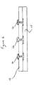
- the joint region in Figure 1 comprises two steel pipes 1 and 2, having anti-corrosion coatings 3 and 4, and weight coatings 5 and 6.
- the anti-corrosion coatings and the weight coatings are cut back to expose lengths of bare pipe which are welded at 7.
- a heat recoverable wraparound sleeve 8 internally coated with a mastic, sold by Raychem Corporation under the trade mark Thermofit WPC TM is shrunk over the weld and overlaps the anti-corrosion coatings on each side of the weld.
- the wraparound sleeve may be provided with an adhesive patch closure, or a suitable mechanical closure, for example a rail and channel closure.
- Figure 2 shows the joint with the enclosure 9 in position, leaving an annular space 10 around the joint region.
- the enclosure comprises a pair of half-shells 10 and 11 which are sized such that when placed over the joint region a gap 12 is left between their longitudinal edges.
- the half-shells are secured to the pipes with heat recoverable fabric sleeves 13 and 14, which are sold by Raychem Corporation under the trade mark Rayfort TM .
- the sleeves 13 and 14 are internally coated with a hot-melt adhesive to provide greater shear strength to prevent the casing from sliding along the pipe.
- the sleeves also round off the edges of the half-shells, thus allowing the enclosure to ride more easily over the rollers of the stinger.
- a joint marking patch (or plate) as shown in Figure 4 can be used for identification of any particular joint and can be pre-installed on one shell or installed immediately after recoverable sleeve installation.
- the marking patch consists of a cross-linked polymer or other plastic sheet 15 into which any number of copper metal studs 16 are embedded with the heads proud of the sheet upper surface. Any desired identification of numbers/letters/symbols can be obtained by installing the copper studs according to the required pattern. During subsea service the copper heads will prevent marine growth attachment and will therefore be permanently visible to divers or subsea inspection vehicles.
- the under surface of the polymer sheet is precoated with a suitable heat activated adhesive 17 which will bond to the half-shells wall material when the patch is heated (usually by gas torch).
- the identification patch can be installed by tieing, clamping, using contact type adhesives or by incorporating magnetic devices within the polymer matrix which then automatically attach the patch to any steel surface.
- the weight of water which fills the joint region will normally be sufficient to provide enough negative or neutral buoyancy, it may on occasions be necessary to add to the joint region a heavier medium such as sand, gravel.
- a heavier medium such as sand, gravel.
- the two half-shells can be installed with the bottom joint section closed together, leaving only the top section open to allow entry of such media.
- the method of this invention does not require special storage, high temperature melting or handling of hazardous or shelf life sensitive materials.
- the method requires no mixing or complex equipment in order to complete a fast, easy and high quality installation. Once installed the system can easily be re-entered should a weld need repair. Within a few minutes after completion the system reaches its maximum mechanical strength prior to contact with the stinger.
- the system allows cathodic protection current to reach directly any coating flaws and does not contain any corrodeable metallic parts that could damage fishing nets.
- Each joint can be permanently marked with an individual identification mark which is unaffected by marine growth or corrosion, thereby allowing a diver to identify any specific joint and also confirm his own position on the sea bed.
Landscapes
- Engineering & Computer Science (AREA)
- General Engineering & Computer Science (AREA)
- Mechanical Engineering (AREA)
- Chemical & Material Sciences (AREA)
- Materials Engineering (AREA)
- Metallurgy (AREA)
- Organic Chemistry (AREA)
- Prevention Of Electric Corrosion (AREA)
- Non-Disconnectible Joints And Screw-Threaded Joints (AREA)
- Joints Allowing Movement (AREA)
- Laying Of Electric Cables Or Lines Outside (AREA)
- Protection Of Pipes Against Damage, Friction, And Corrosion (AREA)
Claims (10)
- Korrosionsschutzanordnung einer Verbindung zwischen zwei korrodierbaren, mit Beschwerungsüberzügen versehenen langgestreckten Substraten, die im Verbindungsbereich vom Beschwerungsüberzug befreit sind, wobei die Anordnung eine an dem langgestreckten Substrat um den Verbindungsbereich herum befestigte Kapsel umfaßt und der Verbindungsbereich in Meerwasser eintaucht, dadurch gekennzeichnet, daß die an dem Substrat befestigte Kapsel hohl ist und wenigstens eine Öffnung aufweist, so daß Meerwasser in die Kapsel ein- und aus ihr austritt, wobei es mit allen freiliegenden Teile der korrodierbaren Substrate in Kontakt gelangt und den Durchgang eines kathodischen Schutzstroms zu den freiliegenden Teilen zuläßt, und daß an einem der langgestreckten Substrate außerhalb der Kapsel eine Anode positioniert ist.
- Anordnung nach Anspruch 1, wobei die Kapsel Polymermaterial umfaßt.
- Anordnung nach einem der Ansprüche 1 bis 2, wobei die korrodierbaren Substrate unter dem Beschwerungsüberzug auch einen Korrosionsschutzüberzug tragen, der im Verbindungsbereich ebenfalls entfernt ist, jedoch innerhalb der Kapsel teilweise über den entfernten Beschwerungsüberzug hinaus verläuft, wobei die Anordnung eine zusätzliche Korrosionsschutzschicht in Form einer wärmerückstellbaren Hülse umfaßt, die direkt über der Verbindung zwischen den Rohren rückgestellt ist, wobei das Meerwasser den Durchgang des kathodischen Schutzstroms zu allen Defekten in allen Korrosionsschutzüberzügen zuläßt.
- Anordnung nach einem der vorhergehenden Ansprüche, wobei die langgestreckten Substrate untergetauchte Rohrleitungen, vorzugsweise untergetauchte Unterwasser-Rohrleitungen umfassen.
- Anordnung nach einem der vorhergehenden Ansprüche, wobei die Kapsel durch eine wärmeschrumpfbare Hülse an dem langgestreckten Substrat befestigt ist.
- Anordnung nach Anspruch 5, wobei die Kapsel ein wärmeschrumpfbares Material umfaßt.
- Anordnung nach Anspruch 5 oder 6, wobei die Kapsel auf der dem Substrat zugewandten Oberfläche mit einer Dichtmaterialschicht beschichtet ist.
- Anordnung nach einem der vorhergehenden Ansprüche, wobei die Öffnung in Form eines im wesentlichen in Längsrichtung der Kapsel verlaufenden Schlitzes ausgebildet ist.
- Anordnung nach Anspruch 2 oder einem darauf rückbezogenen Anspruch, wobei die polymere Kapsel mit sichtbaren oder erkennbaren Identifikationsmitteln gekennzeichnet ist.
- Verfahren zum Schutz einer Verbindung zwischen zwei korrodierbaren, mit Beschwerungsüberzügen versehenen langgestreckten Substraten, die im Verbindungsbereich von der Beschwerungsschicht befreit sind, umfassend folgende Schritte:(i) Umgeben des Verbindungsbereichs mit einer hohlen Kapsel, und(ii) Befestigen der Kapsel an dem langgestreckten Substrat derart, daß um den Verbindungsbereich herum ein Ringraum gebildet wird, wobei wenigstens eine Öffnung für den Ein- und Austritt eines Fluids in den Ringraum vorhanden ist, dadurch gekennzeichnet, daß das Verfahren ferner folgende Schritte umfaßt:(iii) Positionieren einer Anode an einem der Substrate außerhalb der Kapsel, und(iv) Eintauchen des Verbindungsbereichs in Meerwasser derart, daß das Meerwasser in den Ringraum eintritt und ihn im wesentlichen ausfüllt, wobei es mit allen freiliegenden Teilen der korrodierbaren Substrate in Kontakt gelangt und den Durchgang eines kathodischen Schutzstroms zu den freiliegenden Teilen zuläßt.
Applications Claiming Priority (2)
| Application Number | Priority Date | Filing Date | Title |
|---|---|---|---|
| GB868629938A GB8629938D0 (en) | 1986-12-15 | 1986-12-15 | Protection of joints in elongate substrates |
| GB8629938 | 1986-12-15 |
Publications (2)
| Publication Number | Publication Date |
|---|---|
| EP0272075A1 EP0272075A1 (de) | 1988-06-22 |
| EP0272075B1 true EP0272075B1 (de) | 1991-07-24 |
Family
ID=10609033
Family Applications (1)
| Application Number | Title | Priority Date | Filing Date |
|---|---|---|---|
| EP19870311000 Expired EP0272075B1 (de) | 1986-12-15 | 1987-12-15 | Schutz der Verbindungsstellen in länglichen Bauteilen |
Country Status (4)
| Country | Link |
|---|---|
| EP (1) | EP0272075B1 (de) |
| DE (1) | DE3771680D1 (de) |
| GB (1) | GB8629938D0 (de) |
| NO (1) | NO175327C (de) |
Families Citing this family (3)
| Publication number | Priority date | Publication date | Assignee | Title |
|---|---|---|---|---|
| US6309143B1 (en) * | 1998-05-27 | 2001-10-30 | Stanley Merjan | Composite pile with tapering lower portion and method for driving pile into granular soil |
| US10113681B2 (en) | 2013-05-16 | 2018-10-30 | Lockheed Martin Corporation | Pressure compensated enclosures for submerged joints |
| CN107620847A (zh) * | 2017-09-12 | 2018-01-23 | 上海道盾科技股份有限公司 | 一种减缓套管内管道腐蚀的施工方法 |
Family Cites Families (3)
| Publication number | Priority date | Publication date | Assignee | Title |
|---|---|---|---|---|
| GB1564621A (en) * | 1976-02-19 | 1980-04-10 | Shell Int Research | Pipeline provided of a crack or collapse along the length of the pipeline |
| DD130071A1 (de) * | 1977-02-16 | 1978-03-01 | Dieter Severin | Aktivanoden zum korrosionsschutz innenliegender schweissnahtzonen an metallischen hohlkoerpern |
| JPS5887015A (ja) * | 1981-11-18 | 1983-05-24 | Ube Ind Ltd | 被覆鋼管の接続部の被覆保護層形成方法 |
-
1986
- 1986-12-15 GB GB868629938A patent/GB8629938D0/en active Pending
-
1987
- 1987-12-14 NO NO875192A patent/NO175327C/no unknown
- 1987-12-15 EP EP19870311000 patent/EP0272075B1/de not_active Expired
- 1987-12-15 DE DE8787311000T patent/DE3771680D1/de not_active Expired - Lifetime
Also Published As
| Publication number | Publication date |
|---|---|
| GB8629938D0 (en) | 1987-01-28 |
| EP0272075A1 (de) | 1988-06-22 |
| NO175327B (no) | 1994-06-20 |
| DE3771680D1 (de) | 1991-08-29 |
| NO175327C (no) | 1994-09-28 |
| NO875192D0 (no) | 1987-12-14 |
| NO875192L (no) | 1988-06-16 |
Similar Documents
| Publication | Publication Date | Title |
|---|---|---|
| EP0921923B1 (de) | Schutz von rohrleitungsverbindungen | |
| AU2001234836B2 (en) | Apparatus for forming field joints on plastic coated pipe | |
| CA1226449A (en) | Plastic pile protector | |
| US7472476B2 (en) | Method of applying joint infill cladding to pipe | |
| AU2001234836A1 (en) | Apparatus for forming field joints on plastic coated pipe | |
| US4708527A (en) | Plastic pile protector and method of covering a pile with same | |
| GB2119884A (en) | Improvements relating to heat insulated pipe systems | |
| Harris et al. | New coatings for the corrosion protection of steel pipelines and pilings in severely aggressive environments | |
| EP0272075A1 (de) | Schutz der Verbindungsstellen in länglichen Bauteilen | |
| WO1993024782A1 (en) | Protection of pipe joints | |
| US4776613A (en) | Pipe joint weld collar and method of installation | |
| WO1999056055A1 (en) | Pipe corrosion protection | |
| EP0079610A1 (de) | Verfahren zum Formen eines Schutzüberzuges an einer Verbindungsstelle zwischen verkleideten Stahlrohren | |
| US20070240816A1 (en) | Protective girth-weld cover with air release | |
| EP0132332B1 (de) | Kathodisches Schutzsystem für Rohrleitungen | |
| EP0840868B1 (de) | Rohrbeschichtung und rohr mit dieser beschichtung | |
| Bell et al. | Making'Baggies' Work for Ductile Iron Pipe | |
| WO1996028684A9 (en) | Pipe coating | |
| Keeling | Corrosion Protection Features Of the Hyperion Ocean Outfall | |
| JPH06240699A (ja) | 防食鋼管継手部の被覆方法 | |
| CA1333211E (en) | Method of Pipeline Joint Coating and Insulation | |
| JPH0344487A (ja) | 鋼材の防食被覆層の損傷部の補修方法 | |
| NL2016645B1 (en) | Pipeline comprising anodes and method of laying said pipeline. | |
| John et al. | Improved corrosion control by coating in the splash zone and subsea | |
| Miley | Application of Plastic Tape to NATURAL GAS PIPELINE |
Legal Events
| Date | Code | Title | Description |
|---|---|---|---|
| PUAI | Public reference made under article 153(3) epc to a published international application that has entered the european phase |
Free format text: ORIGINAL CODE: 0009012 |
|
| 17P | Request for examination filed |
Effective date: 19871228 |
|
| AK | Designated contracting states |
Kind code of ref document: A1 Designated state(s): DE FR GB IT NL |
|
| 17Q | First examination report despatched |
Effective date: 19891011 |
|
| GRAA | (expected) grant |
Free format text: ORIGINAL CODE: 0009210 |
|
| AK | Designated contracting states |
Kind code of ref document: B1 Designated state(s): DE FR GB IT NL |
|
| PG25 | Lapsed in a contracting state [announced via postgrant information from national office to epo] |
Ref country code: IT Free format text: LAPSE BECAUSE OF FAILURE TO SUBMIT A TRANSLATION OF THE DESCRIPTION OR TO PAY THE FEE WITHIN THE PRE;WARNING: LAPSES OF ITALIAN PATENTS WITH EFFECTIVE DATE BEFORE 2007 MAY HAVE OCCURRED AT ANY TIME BEFORE 2007. THE CORRECT EFFECTIVE DATE MAY BE DIFFERENT FROM THE ONE RECORDED.SCRIBED TIME-LIMIT Effective date: 19910724 Ref country code: NL Effective date: 19910724 |
|
| REF | Corresponds to: |
Ref document number: 3771680 Country of ref document: DE Date of ref document: 19910829 |
|
| ET | Fr: translation filed | ||
| NLV1 | Nl: lapsed or annulled due to failure to fulfill the requirements of art. 29p and 29m of the patents act | ||
| PLBE | No opposition filed within time limit |
Free format text: ORIGINAL CODE: 0009261 |
|
| STAA | Information on the status of an ep patent application or granted ep patent |
Free format text: STATUS: NO OPPOSITION FILED WITHIN TIME LIMIT |
|
| 26N | No opposition filed | ||
| PGFP | Annual fee paid to national office [announced via postgrant information from national office to epo] |
Ref country code: FR Payment date: 19951212 Year of fee payment: 9 |
|
| PGFP | Annual fee paid to national office [announced via postgrant information from national office to epo] |
Ref country code: DE Payment date: 19951214 Year of fee payment: 9 |
|
| PG25 | Lapsed in a contracting state [announced via postgrant information from national office to epo] |
Ref country code: FR Effective date: 19970829 |
|
| PG25 | Lapsed in a contracting state [announced via postgrant information from national office to epo] |
Ref country code: DE Effective date: 19970902 |
|
| REG | Reference to a national code |
Ref country code: FR Ref legal event code: ST |
|
| REG | Reference to a national code |
Ref country code: GB Ref legal event code: IF02 |
|
| PGFP | Annual fee paid to national office [announced via postgrant information from national office to epo] |
Ref country code: GB Payment date: 20051207 Year of fee payment: 19 |
|
| GBPC | Gb: european patent ceased through non-payment of renewal fee |
Effective date: 20061215 |
|
| PG25 | Lapsed in a contracting state [announced via postgrant information from national office to epo] |
Ref country code: GB Free format text: LAPSE BECAUSE OF NON-PAYMENT OF DUE FEES Effective date: 20061215 |