EP0272523A2 - Accouplement pour outil - Google Patents
Accouplement pour outil Download PDFInfo
- Publication number
- EP0272523A2 EP0272523A2 EP87118038A EP87118038A EP0272523A2 EP 0272523 A2 EP0272523 A2 EP 0272523A2 EP 87118038 A EP87118038 A EP 87118038A EP 87118038 A EP87118038 A EP 87118038A EP 0272523 A2 EP0272523 A2 EP 0272523A2
- Authority
- EP
- European Patent Office
- Prior art keywords
- tool
- bore
- pin
- coupling according
- tool head
- Prior art date
- Legal status (The legal status is an assumption and is not a legal conclusion. Google has not performed a legal analysis and makes no representation as to the accuracy of the status listed.)
- Granted
Links
Images

Classifications
-
- B—PERFORMING OPERATIONS; TRANSPORTING
- B23—MACHINE TOOLS; METAL-WORKING NOT OTHERWISE PROVIDED FOR
- B23B—TURNING; BORING
- B23B31/00—Chucks; Expansion mandrels; Adaptations thereof for remote control
- B23B31/02—Chucks
- B23B31/10—Chucks characterised by the retaining or gripping devices or their immediate operating means
- B23B31/11—Retention by threaded connection
- B23B31/1107—Retention by threaded connection for conical parts
-
- B—PERFORMING OPERATIONS; TRANSPORTING
- B23—MACHINE TOOLS; METAL-WORKING NOT OTHERWISE PROVIDED FOR
- B23B—TURNING; BORING
- B23B31/00—Chucks; Expansion mandrels; Adaptations thereof for remote control
- B23B31/006—Conical shanks of tools
-
- B—PERFORMING OPERATIONS; TRANSPORTING
- B23—MACHINE TOOLS; METAL-WORKING NOT OTHERWISE PROVIDED FOR
- B23B—TURNING; BORING
- B23B31/00—Chucks; Expansion mandrels; Adaptations thereof for remote control
- B23B31/008—Chucks; Expansion mandrels; Adaptations thereof for remote control with arrangements for transmitting torque
-
- B—PERFORMING OPERATIONS; TRANSPORTING
- B23—MACHINE TOOLS; METAL-WORKING NOT OTHERWISE PROVIDED FOR
- B23B—TURNING; BORING
- B23B31/00—Chucks; Expansion mandrels; Adaptations thereof for remote control
- B23B31/02—Chucks
- B23B31/10—Chucks characterised by the retaining or gripping devices or their immediate operating means
- B23B31/11—Retention by threaded connection
- B23B31/1107—Retention by threaded connection for conical parts
- B23B31/1122—Retention by threaded connection for conical parts using cylindrical threads
-
- B—PERFORMING OPERATIONS; TRANSPORTING
- B23—MACHINE TOOLS; METAL-WORKING NOT OTHERWISE PROVIDED FOR
- B23B—TURNING; BORING
- B23B2270/00—Details of turning, boring or drilling machines, processes or tools not otherwise provided for
- B23B2270/06—Use of elastic deformation
Definitions
- the invention relates to a tool coupling for connecting a tool head and a tool holder with anti-rotation and axial preload, in which the tool head serving as a tool has an at least partially tapered receiving pin, a threaded bore and an annular contact collar, and the tool holder has an at least partially conical sleeve-shaped receiving bore corresponding to the receiving pin and have a tightening screw and an annular contact surface.
- Such couplings are e.g. described in the older German application P 35 32 891.6 and required in particular for cutting tools that can be automatically clamped and handled.
- the object described in the aforementioned patent application has at its bolt-like clamping end a flat surface with a subsequent short cone, a cylindrical part and at the rear end a support part which can be cylindrical or as a short cone.
- This clamping part of the tool head which is also referred to as a mounting pin, is inserted into a corresponding hole in a tool holder.
- the tool holder also has a flat surface, further a subsequent one Boring, which is short-tapered in the front part, and finally has a cylindrical part and a leading fitting part.
- the preload achieved in this way in the front short cone area is of such a size that there is no complete reduction of the preload down to zero or no relief in the unloaded area in the case of transverse forces such as occur during milling or turning.
- the rear, cylindrical fitting part naturally has a slight clearance fit.
- a slight radial prestress can be selected, so that this fitting part serves to support large transverse forces which occur on the tool cutting edges.
- EP 0 106 087 B1 which is characterized by a continuously conical design of the clamping part.
- This out In terms of manufacturing technology, an advantageous construction results in a full load of the cone from front to back and with the same axial clamping force, a significantly reduced preload and thus less surface pressure. If large transverse forces occur on the tool cutting edges in the unloaded area of the cone, this has the effect that the preload becomes zero and a pounding effect arises, since each cutting process has a dynamic or oscillating proportion of significant quantities.
- the tapered locating pin of the tool head has a blind bore on the end face which runs centrally to the longitudinal central axis. Through this hole, the remaining cross-section can be easily deformed by radial forces like a pipe, since the diameter of the clamping pin of the tool head can be reduced. Nevertheless, the locating pin has a high bending stiffness. This results in a given axial force and a continuous taper executed clamping part in the front cone part the desired high surface pressure and in the rear cone area naturally a lower
- the blind bore can either be cylindrical, step-shaped with a bore diameter that increases in the direction of the smallest diameter of the locating pin, or it can be frustoconical.
- the blind bore can either be cylindrical, step-shaped with a bore diameter that increases in the direction of the smallest diameter of the locating pin, or it can be frustoconical.
- the object according to the invention can be optimally achieved if the depth of the blind bore is so great that it makes up 1/2 to 7/8 the length of the receiving pin of the tool head.
- the cross-section of the bore should be 70 to 97% of the smallest diameter of the locating pin. If the specified dimensions are adhered to, the bore can be designed in the case of a stepped bore or tapered bore in such a way that the surface pressure in the conical part caused by prestressing is predetermined and assumes a size such that the radial forces on the tool cutting edges are not relieved in any area Zero occurs in the unloaded cone area.
- transverse bores can then also be used for receiving clamping parts or longitudinal grooves for transmitting torques be introduced without wear occurring at the transitions in the conical region of the tool head and the tool holder in the case of frequent clamping and unclamping cycles.
- the tool coupling shown in Fig. 1 consists essentially of a tool head 1 with a tapered locating pin 3, which has an annular contact collar 5 at the largest diameter.
- the drivers normally provided for indexing the tool head and the corresponding grooves of the tool holder and any circumferential V-shaped grooves for gripping devices in the tool head are omitted.
- a correspondingly shaped conical receiving bore 4 of the tool holder 2 is used to receive the receiving pin 3, which can optionally also be made in an exchangeable receiving sleeve of the tool holder 2.
- the receiving bore 4 has an annular contact surface 7, which comes into contact with the annular contact collar 5 in the tensioned state.
- the elasticity of the receiving pin is ensured by a blind hole 6 provided coaxially to the longitudinal central axis 10 of the tool head 1 in the receiving pin.
- the blind bore 6 is cylindrical in the present case and has a depth t which is approximately 2/3 as large as the entire length l of the receiving pin 3.
- the tool head for example, a cheese head screw 8, which is guided and supported at the end of the mounting pin 3 in a central threaded bore 11 provided there in the mounting pin and in a stepped bore 12, 15 of the tool holder 2. If this cylinder screw 8 is tightened, the locating pin 3 is drawn into the locating bore 4 in accordance with the thread pitch, the elastic deformability of the front part of the locating pin in particular causing the annular contact surface 5 to come into contact with the contact surface 7. The head thus tensioned with the cap screw 8 tightened is shown in FIG. 1.
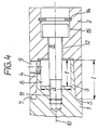
- the radial transverse bore 9 shown in FIG. 4 enables the necessary axial clamping movements to be carried out in connection with further transverse bores, not shown, so that the cylinder screw 8 can be dispensed with.
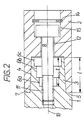
- FIG. 2 shows a further exemplary embodiment of the subject matter of the invention, which differs from the previously described only in that the central blind bore 6 consists of steps 6a, 6b and 6c.
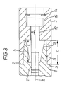
- FIG. 3 represents a tapered blind bore 13.
- FIG. 4 in turn corresponds to that according to FIG. 1 with a cylindrical blind bore 6, in which a radial transverse bore 9 is additionally provided for receiving clamping parts.
- a radial transverse bore 9 is additionally provided for receiving clamping parts.
- Several radial cross bores can also be provided.
- the cylinder screw 8 is unscrewed from the threaded bore of the receiving pin 3 until the head of the cylinder screw rests on a circlip 14 of the tool holder 2, the screw being turned further the tool head 1 with the mounting pin 3 from the mounting hole 4 of the Tool holder 2 moved out.
- the tool head 1 is then removed from the tool holder by means of a gripping device.
- the insertion of the tool head 1 takes place in the reverse order, i.e. the locating pin is inserted into the locating bore 4, then the cylinder screw 8 is tightened until the ring-shaped system 5 bears against the system 7. Since the receiving pin 3 in its front area, i.e. in the area of the bore 6, which has a slight oversize compared to the receiving bore in the correspondingly assigned part, there is a certain preload when inserting the receiving pin into the receiving bore 4 up to the point where the annular contact collar 5 and the contact 7 come to rest, which is not noticeably reduced even when there is lateral force on the tool head, for example when turning or milling. This prevents the tool from hitting the mounting hole.
Landscapes
- Engineering & Computer Science (AREA)
- Mechanical Engineering (AREA)
- Gripping On Spindles (AREA)
- Cutting Tools, Boring Holders, And Turrets (AREA)
Applications Claiming Priority (2)
| Application Number | Priority Date | Filing Date | Title |
|---|---|---|---|
| DE3642132A DE3642132C1 (de) | 1986-12-10 | 1986-12-10 | Werkzeugkupplung zur Verbindung eines Werkzeugschaftes und eines Werkzeughalters |
| DE3642132 | 1986-12-10 |
Publications (3)
| Publication Number | Publication Date |
|---|---|
| EP0272523A2 true EP0272523A2 (fr) | 1988-06-29 |
| EP0272523A3 EP0272523A3 (en) | 1990-01-24 |
| EP0272523B1 EP0272523B1 (fr) | 1992-11-11 |
Family
ID=6315856
Family Applications (1)
| Application Number | Title | Priority Date | Filing Date |
|---|---|---|---|
| EP19870118038 Expired - Lifetime EP0272523B1 (fr) | 1986-12-10 | 1987-12-05 | Accouplement pour outil |
Country Status (6)
| Country | Link |
|---|---|
| EP (1) | EP0272523B1 (fr) |
| JP (1) | JPS63162106A (fr) |
| AU (1) | AU602034B2 (fr) |
| CA (1) | CA1291649C (fr) |
| DE (1) | DE3642132C1 (fr) |
| IN (1) | IN168758B (fr) |
Cited By (2)
| Publication number | Priority date | Publication date | Assignee | Title |
|---|---|---|---|---|
| WO1999016517A1 (fr) * | 1997-09-30 | 1999-04-08 | Yuanxu Qiao | Table de billard anglais |
| EP1008408A3 (fr) * | 1998-12-09 | 2003-01-08 | Mitsubishi Materials Corporation | Outil de coupe type ajustement serré |
Families Citing this family (7)
| Publication number | Priority date | Publication date | Assignee | Title |
|---|---|---|---|---|
| RU1791075C (ru) * | 1989-02-10 | 1993-01-30 | Н. И. Чепелев, Г. М Целковнев. Л. П.Кузнецов и Г. И. Пинхусович | Устройство соединени модулей |
| DE3930245A1 (de) * | 1989-09-11 | 1991-03-14 | Otto Zettl | Kupplungseinrichtung fuer modulare werkzeugsysteme |
| EP0508152B1 (fr) * | 1991-03-13 | 1996-01-10 | Mitsubishi Materials Corporation | Outil de coupe |
| DE4402483A1 (de) * | 1993-12-23 | 1995-06-29 | Johne & Co Praezisionswerkzeug | Werkzeughalter oder dergleichen |
| DE19600239C1 (de) * | 1996-01-05 | 1997-04-10 | Ima Maschinenfabriken Klessmann Gmbh | Bearbeitungsaggregat für Werkstücke aus Holz und/oder Holzaustauschstoffen |
| ES2143841T3 (es) * | 1997-04-30 | 2000-05-16 | Bacci Paolino Di Giuseppe Bacc | Herramienta rotatoria para una maquina-herramienta y maquina-herramienta que utiliza dicha herramienta. |
| CN109623645A (zh) * | 2018-12-18 | 2019-04-16 | 重庆跃进机械厂有限公司 | 一种哈夫凸轮固定工装及加工方法 |
Family Cites Families (9)
| Publication number | Priority date | Publication date | Assignee | Title |
|---|---|---|---|---|
| SE423875B (sv) * | 1979-02-07 | 1982-06-14 | Sandvik Ab | Verktygskoppling mellan ett skervertkyg och en maskinspindel |
| IT8128959U1 (it) * | 1981-03-17 | 1982-09-17 | Utensileria Sassolese S A S Di Casanova Emilio Liverani Edgardo & C | Dispositivo autocentrante per l'accoppiamento degli utensili al mandrino di macchine utensili. |
| DE3237128A1 (de) * | 1982-10-07 | 1984-04-12 | Wilhelm Fette Gmbh, 2053 Schwarzenbek | Kombinationswerkzeug |
| DE3314591A1 (de) * | 1983-04-22 | 1984-10-25 | Montanwerke Walter GmbH, 7400 Tübingen | Mehrteiliges spannsystem, insbesondere fuer rundlaufende werkzeuge |
| GB2154479A (en) * | 1984-02-03 | 1985-09-11 | Gen Electric | Machine tool |
| DE3410563C2 (de) * | 1984-03-22 | 1986-10-02 | J. Kühn GmbH & Co Präzisionswerkzeug KG, 4270 Dorsten | Spannvorrichtung für Werkzeuge od.dgl. |
| US4680999A (en) * | 1984-07-11 | 1987-07-21 | Kyoritsu Seiki Corporation | Replaceable tool |
| DE3532891A1 (de) * | 1985-09-14 | 1987-03-26 | Krupp Gmbh | Werkzeugkupplung |
| DE3541236A1 (de) * | 1985-11-21 | 1987-05-27 | Ott Gmbh A | Werkzeugkupplung |
-
1986
- 1986-12-10 DE DE3642132A patent/DE3642132C1/de not_active Expired
-
1987
- 1987-12-05 EP EP19870118038 patent/EP0272523B1/fr not_active Expired - Lifetime
- 1987-12-09 CA CA000553880A patent/CA1291649C/fr not_active Expired - Lifetime
- 1987-12-10 AU AU82410/87A patent/AU602034B2/en not_active Ceased
- 1987-12-10 JP JP31116387A patent/JPS63162106A/ja active Pending
-
1988
- 1988-02-29 IN IN173/CAL/88A patent/IN168758B/en unknown
Cited By (2)
| Publication number | Priority date | Publication date | Assignee | Title |
|---|---|---|---|---|
| WO1999016517A1 (fr) * | 1997-09-30 | 1999-04-08 | Yuanxu Qiao | Table de billard anglais |
| EP1008408A3 (fr) * | 1998-12-09 | 2003-01-08 | Mitsubishi Materials Corporation | Outil de coupe type ajustement serré |
Also Published As
| Publication number | Publication date |
|---|---|
| AU602034B2 (en) | 1990-09-27 |
| EP0272523A3 (en) | 1990-01-24 |
| JPS63162106A (ja) | 1988-07-05 |
| IN168758B (fr) | 1991-06-01 |
| AU8241087A (en) | 1988-06-16 |
| DE3642132C1 (de) | 1988-03-24 |
| CA1291649C (fr) | 1991-11-05 |
| EP0272523B1 (fr) | 1992-11-11 |
Similar Documents
| Publication | Publication Date | Title |
|---|---|---|
| DE69700671T2 (de) | Sicherungsmutter | |
| DE69522439T2 (de) | Blindbefestigungselement mit verformbarer hülse | |
| DE102009060678B4 (de) | Werkzeugträger mit einer Spannzangenaufnahme und Werkzeugeinsatz zur Verwendung in einem Werkzeugträger | |
| EP0295315B1 (fr) | Assemblage d'outil | |
| EP0037554B1 (fr) | Outil de coupe | |
| DE2061565C3 (de) | Spannfutter für Werkzeuge mit zylindrischem Schaft | |
| DE4237618C2 (de) | Befestigungsanordnung für einen Werkzeughalter auf einer Werkzeugmaschine | |
| EP2301696A1 (fr) | Interface entre un corps de réception et un insert, l'insert étant notamment développé comme support d'outil ou de pièce à usiner | |
| EP0284745B1 (fr) | Accouplement entre une tête d'outil et un porte-outil | |
| CH632065A5 (de) | Duebel mit spreizhuelse und spreizkoerper. | |
| DE3612514A1 (de) | Fraeser | |
| DE3230688A1 (de) | Fraeswerkzeug | |
| DE3912503A1 (de) | Spanneinrichtung fuer auswechselbare werkzeugkoepfe | |
| DE3814550C1 (en) | Clamping device for clamping two machine parts releasable from one another | |
| DE69007533T2 (de) | Klemmstahlhalter. | |
| DE102017127814A1 (de) | Werkzeug zur spanenden Bearbeitung eines Werkstücks | |
| DE3041650C2 (de) | Rollkupplungsfutter | |
| EP0272523B1 (fr) | Accouplement pour outil | |
| DE29822209U1 (de) | Gewindespindelantrieb für ein Federspanngerät mit einem im Überlastfall abscherenden Sicherungsstift | |
| EP0106087B1 (fr) | Outil combiné | |
| DE102019115387A1 (de) | Spannvorrichtung zum Einspannen eines Gegenstands, insbesondere eines Werkzeugs | |
| DE3410563C2 (de) | Spannvorrichtung für Werkzeuge od.dgl. | |
| EP3275597A1 (fr) | Outil et procédé de montage et démontage de composants | |
| DE1919439B2 (de) | Schnellspannfutter für einen Schaft aufweisende Werkzeuge | |
| WO1983001030A1 (fr) | Dispositif de protection contre les surcharges dans une machine-outil |
Legal Events
| Date | Code | Title | Description |
|---|---|---|---|
| PUAI | Public reference made under article 153(3) epc to a published international application that has entered the european phase |
Free format text: ORIGINAL CODE: 0009012 |
|
| AK | Designated contracting states |
Kind code of ref document: A2 Designated state(s): CH FR GB IT LI SE |
|
| PUAL | Search report despatched |
Free format text: ORIGINAL CODE: 0009013 |
|
| AK | Designated contracting states |
Kind code of ref document: A3 Designated state(s): CH FR GB IT LI SE |
|
| 17P | Request for examination filed |
Effective date: 19900702 |
|
| 17Q | First examination report despatched |
Effective date: 19910114 |
|
| GRAA | (expected) grant |
Free format text: ORIGINAL CODE: 0009210 |
|
| AK | Designated contracting states |
Kind code of ref document: B1 Designated state(s): CH FR GB IT LI SE |
|
| GBT | Gb: translation of ep patent filed (gb section 77(6)(a)/1977) | ||
| ET | Fr: translation filed | ||
| PG25 | Lapsed in a contracting state [announced via postgrant information from national office to epo] |
Ref country code: LI Free format text: LAPSE BECAUSE OF NON-PAYMENT OF DUE FEES Effective date: 19921231 Ref country code: CH Free format text: LAPSE BECAUSE OF NON-PAYMENT OF DUE FEES Effective date: 19921231 |
|
| ITF | It: translation for a ep patent filed | ||
| PLBI | Opposition filed |
Free format text: ORIGINAL CODE: 0009260 |
|
| REG | Reference to a national code |
Ref country code: CH Ref legal event code: PL |
|
| 26 | Opposition filed |
Opponent name: SANDVIK AKTIEBOLAG Effective date: 19930811 |
|
| PGFP | Annual fee paid to national office [announced via postgrant information from national office to epo] |
Ref country code: FR Payment date: 19931215 Year of fee payment: 7 |
|
| PGFP | Annual fee paid to national office [announced via postgrant information from national office to epo] |
Ref country code: SE Payment date: 19931220 Year of fee payment: 7 |
|
| PGFP | Annual fee paid to national office [announced via postgrant information from national office to epo] |
Ref country code: GB Payment date: 19941018 Year of fee payment: 8 |
|
| PG25 | Lapsed in a contracting state [announced via postgrant information from national office to epo] |
Ref country code: SE Effective date: 19941206 |
|
| EAL | Se: european patent in force in sweden |
Ref document number: 87118038.6 |
|
| RDAG | Patent revoked |
Free format text: ORIGINAL CODE: 0009271 |
|
| STAA | Information on the status of an ep patent application or granted ep patent |
Free format text: STATUS: PATENT REVOKED |
|
| 27W | Patent revoked |
Effective date: 19950210 |
|
| GBPR | Gb: patent revoked under art. 102 of the ep convention designating the uk as contracting state |
Free format text: 950210 |
|
| EUG | Se: european patent has lapsed |
Ref document number: 87118038.6 |