EP0272571A2 - Walzgerüst mit Walzringen - Google Patents
Walzgerüst mit Walzringen Download PDFInfo
- Publication number
- EP0272571A2 EP0272571A2 EP87118456A EP87118456A EP0272571A2 EP 0272571 A2 EP0272571 A2 EP 0272571A2 EP 87118456 A EP87118456 A EP 87118456A EP 87118456 A EP87118456 A EP 87118456A EP 0272571 A2 EP0272571 A2 EP 0272571A2
- Authority
- EP
- European Patent Office
- Prior art keywords
- piston
- cylinder units
- roll
- bearing housings
- pressure
- Prior art date
- Legal status (The legal status is an assumption and is not a legal conclusion. Google has not performed a legal analysis and makes no representation as to the accuracy of the status listed.)
- Granted
Links
- 238000005096 rolling process Methods 0.000 claims abstract description 24
- 238000006073 displacement reaction Methods 0.000 claims description 5
- 230000000284 resting effect Effects 0.000 claims 2
- 238000012544 monitoring process Methods 0.000 claims 1
- 238000000034 method Methods 0.000 description 3
- 230000001105 regulatory effect Effects 0.000 description 3
- 238000003825 pressing Methods 0.000 description 2
- 238000010276 construction Methods 0.000 description 1
- 230000001276 controlling effect Effects 0.000 description 1
- 238000013016 damping Methods 0.000 description 1
- 238000010586 diagram Methods 0.000 description 1
- 230000000694 effects Effects 0.000 description 1
- 230000005489 elastic deformation Effects 0.000 description 1
Images


Classifications
-
- B—PERFORMING OPERATIONS; TRANSPORTING
- B21—MECHANICAL METAL-WORKING WITHOUT ESSENTIALLY REMOVING MATERIAL; PUNCHING METAL
- B21B—ROLLING OF METAL
- B21B13/00—Metal-rolling stands, i.e. an assembly composed of a stand frame, rolls, and accessories
-
- B—PERFORMING OPERATIONS; TRANSPORTING
- B21—MECHANICAL METAL-WORKING WITHOUT ESSENTIALLY REMOVING MATERIAL; PUNCHING METAL
- B21B—ROLLING OF METAL
- B21B37/00—Control devices or methods specially adapted for metal-rolling mills or the work produced thereby
- B21B37/58—Roll-force control; Roll-gap control
- B21B37/62—Roll-force control; Roll-gap control by control of a hydraulic adjusting device
-
- B—PERFORMING OPERATIONS; TRANSPORTING
- B21—MECHANICAL METAL-WORKING WITHOUT ESSENTIALLY REMOVING MATERIAL; PUNCHING METAL
- B21B—ROLLING OF METAL
- B21B13/00—Metal-rolling stands, i.e. an assembly composed of a stand frame, rolls, and accessories
- B21B13/005—Cantilevered roll stands
-
- B—PERFORMING OPERATIONS; TRANSPORTING
- B21—MECHANICAL METAL-WORKING WITHOUT ESSENTIALLY REMOVING MATERIAL; PUNCHING METAL
- B21B—ROLLING OF METAL
- B21B31/00—Rolling stand structures; Mounting, adjusting, or interchanging rolls, roll mountings, or stand frames
- B21B31/02—Rolling stand frames or housings; Roll mountings ; Roll chocks
- B21B31/04—Rolling stand frames or housings; Roll mountings ; Roll chocks with tie rods in frameless stands, e.g. prestressed tie rods
-
- B—PERFORMING OPERATIONS; TRANSPORTING
- B21—MECHANICAL METAL-WORKING WITHOUT ESSENTIALLY REMOVING MATERIAL; PUNCHING METAL
- B21B—ROLLING OF METAL
- B21B31/00—Rolling stand structures; Mounting, adjusting, or interchanging rolls, roll mountings, or stand frames
- B21B31/16—Adjusting or positioning rolls
- B21B31/20—Adjusting or positioning rolls by moving rolls perpendicularly to roll axis
- B21B31/32—Adjusting or positioning rolls by moving rolls perpendicularly to roll axis by liquid pressure, e.g. hydromechanical adjusting
-
- B—PERFORMING OPERATIONS; TRANSPORTING
- B21—MECHANICAL METAL-WORKING WITHOUT ESSENTIALLY REMOVING MATERIAL; PUNCHING METAL
- B21B—ROLLING OF METAL
- B21B31/00—Rolling stand structures; Mounting, adjusting, or interchanging rolls, roll mountings, or stand frames
- B21B31/08—Interchanging rolls, roll mountings, or stand frames, e.g. using C-hooks; Replacing roll chocks on roll shafts
Definitions
- the present invention relates to a roll stand with roll rings which are placed from one side or in a cantilevered manner on a pair of adjustable roll support shafts which are supported on two sides.
- Both roll support shafts have extension journals which project beyond the roll rings.
- Journal bearings can be slid onto and are fixable on the extension journals.
- the journal bearings have bearing housings which are connected with each other in a frictionally engaging manner for absorbing rolling forces by means of piston-cylinder units which can be actuated by a pressure medium and are movable parallel to the direction of adjustment of the roll support shafts, wherein one of the bearing housings is connected to the piston rods of the piston-cylinder unit and the other bearing housing, which supports the piston-cylinder unit, has sliding guide means for these piston rods.
- Roll stands of this type can absorb substantially greater rolling forces than roll stands which do not have the bearing housings for the journal bearings which can be slid onto and fixed on the extension journals.
- the pressure-actuated piston-cylinder units connected to the bearing housings make it possible to absorb a substantial portion of the rolling forces when the roll rings are supported from one side. In the past, this had only been possible when the roll or roll rings had been supported on two sides on both sides of the roll or roll ring in normal roll stands having two roll housings connected by means of transverse support members.
- both journal portions of the roll support shafts which carry the rolls resiliently return by a certain distance toward the roll gap after the end of the rolling stock section has left the roll gap, so that the effect of the above-described impacts is further increased.
- the primary object of the present invention to provide a roll stand in which the above-described disadvantages are avoided and, consequently, the stiffness of the roll stand is increased.
- the roll stand of the type described above includes additional piston-cylinder units arranged between the two bearing housings.
- the cylinders and pistons of the additional piston-cylinder units are guided by the piston rods of the other piston-cylinder units which connect the bearing housings.
- the pistons of the additional piston-cylinder units rest against one of the two bearing housings and the cylinders of the additional piston-cylinder units rest against the other of the bearing housings. Pressure can be applied to the additional piston-cylinder units independently of the other piston-cylinder units.
- the piston-cylinder units whose piston rods connect the two bearing housings and the piston-cylinder units which are arranged between the bearing housings have the same working surface areas and are connected to a common pressure generating unit, but the pressure acting on the respective piston-cylinder units is individually adjustable and the respective piston-cylinder units can be individually separated from the pressure generating unit and can be closed individually.
- a displacement pickup may be provided which monitors the spacing between the bearing housings and which is capable of influencing a position adjusting and controlling device for the piston-cylinder units whose piston-rods connect the bearing housings.
- the piston-cylinder units arranged between the bearing housings may be pairs of axially spaced apart piston-cylinder units which can be actuated simultaneously and together with pressure.
- the piston-cylinder units may be arranged in a roll housing which is rigidly connected to the roll stand, wherein the bearing housings define recesses which are open toward the roll stand and surround the cylinders and the piston rods of the piston-cylinder units and which define contact seat surfaces for the cylinders and/or the pistons of the piston-cylinder units and include releasable fixing elements for the latter.
- the two bearing housings can be pretensioned against the rolling pressure as is the case in known constructions for keeping constant the adjusted width of the rolling gap, while, by applying pressure to the piston-cylinder units whose piston rods connect the bearing housings as well as to the piston-cylinder units which are arranged between the bearing housings, a bracing of the bearing housings can be achieved which corresponds to a bracing which is achievable by screws.
- the piston rods expand and cause a corresponding decrease of the pressure in the piston-cylinder units arranged between the bearing housings.
- the adjustment movements of the bearing housings are carried out with positive balancing, wherein the pretensioning of the bearing housings relative to each other is maintained, i.e., the piston rods remain under tensile load and the piston-cylinder units arranged between the bearing housings exert a pressure on both bearing housings.
- This pressure further means that the bearing play of the journal portions of the roll support shafts can be eliminated when the piston-cylinder units arranged between the bearing housings are dimensioned in such a way that the pressure generated by these units on the bearing housings is slightly greater than the tensioning pressure exerted by the piston-cylinder units connecting the bearing housings and, consequently, a positive balancing of the bearing housings is achieved.
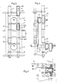
- bearing housings or chocks 2 and 3 which receive journal portions 1a of roll support shafts 1 are connected through piston rods 4a of piston-cylinder units 4.
- An end face of a cylinder 4b of each piston-cylinder unit 4 rests on one of the bearing housings 2.
- Piston rods 4a extend through a bore 2a of this bearing housing and through another bore 3a of the bearing housing 3 and are fixed by means of screws 5.
- Additional piston-cylinder units 6 are arranged between the bearing housings 2 and 3. As illustrated in the drawing, the end face of the piston 6c of each piston-cylinder unit 6 rests against the bearing housing 2 and an end face of cylinder 6b rests against the other bearing housing 3.
- cylinder 6b The outer surface of cylinder 6b is slidingly guided in guide means 2b of the bearing housing 2; also, cylinder 6b and piston 6c of this piston-cylinder unit slides on the piston rod 4a of piston-cylinder unit 4 which piston rod 4a extends centrally through appropriate bores provided in piston-cylinder unit 6.
- pairs of piston-cylinder units are arranged between the bearing housings 2 and 3 axially spaced apart by a distance D.
- the pairs of piston-cylinder units are arranged in a support frame 7 which is illustrated in dash-dotted lines. This arrangement makes it possible to use piston-cylinder units with short strokes even if the width of the roll gap is great.
- Fig. 5 of the drawing shows that, in the embodiment of Figs. 3 and 4, the bearing housings 2 and 3 have recesses with contact seat surfaces 3d, which recesses are open toward the roll stand 8 and surround the cylinders 4b and 6b ⁇ and 6b ⁇ and the piston rods 4a of the piston-cylinder units 4.
- These recesses make it possible to remove the bearing housings 2 and 3 together with the roll rings 10 from the journal portions 1a of the oll support shafts 1, without having to separate the connection of the piston-cylinder units 4 and 6 with the support frame 7.
- the piston-cylinder units 4 and 6 as well as the support frame 7 remain connected to the roll stand 8.
- roll ring 10 is supported by a sleeve-like extension 11a of an inner ring 11 of journal bearing 12.
- the pressure to be applied is generated by a pump 21 secured by a pressure relief valve 22.
- a magnet b of a solenoid valve 28 applies pressure to the piston-cylinder unit 6.
- the pressure is regulated at pressure-reducing valve 26.
- a possibility for relief is provided for a hydraulically controlled check valve 20 via a directional control valve 13.
- a pressure increase due to mass and spring forces which occur when the rolling stock section leaves the roll gap can be limited by means of the damping reservoir 14.
- Pressure is applied to the piston-cylinder units 4 by actuating magnet b of solenoid valve 27, the pressure regulation being carried out at pressure-reducing valve 25.
- a possibility for relief is provided by a hydraulically controlled check valve 29 via directional control valve 15. Any pressure increase occurring during rolling can be limited by means of pressure relief valve 16.
- a possibility for additional intake is provided by means of check valve 17 when the rolling stock section leaves the rolling gap.
- a pressure application to piston-cylinder units 6 acts to bridge the bearing play and a pressure application to piston-cylinder units 4 acts to create the pretension through piston rods 4a.
- the hydraulically controlled check valves 29 and 20 serve to maintain the respectively adjusted pressure within the piston-cylinder units and the pretensioned pressure medium volumes act as stacks of springs would. After each pass, the piston-cylinder units 4 and 6 are relieved by opening the hydraulically controlled check valves 29 and 20; subsequently, the above-described procedure is repeated.
- a displacement pickup which monitors the spacing between the bearing housings 2 and 3 and position adjustment and control devices for the piston-cylinder units 4 which devices are influenced by the displacement pickup can be used for regulating the operation if valve 27 is replaced by a power-assisted valve and a pressure reservoir is arranged in the feedline to this pressure-assisted valve. In this case, pressure valve 25 is omitted.
- the power-assisted valve is used for regulating the pressure in the piston-cylinder unit 4 in accordance with the requirements, i.e., the device can compensate displacement errors caused during rolling, for example, by elastic deformations.
Landscapes
- Engineering & Computer Science (AREA)
- Mechanical Engineering (AREA)
- Rolls And Other Rotary Bodies (AREA)
- Support Of The Bearing (AREA)
- Reduction Rolling/Reduction Stand/Operation Of Reduction Machine (AREA)
- Unwinding Webs (AREA)
- Replacement Of Web Rolls (AREA)
- Rollers For Roller Conveyors For Transfer (AREA)
- Bending Of Plates, Rods, And Pipes (AREA)
- Metal Rolling (AREA)
Priority Applications (1)
| Application Number | Priority Date | Filing Date | Title |
|---|---|---|---|
| AT87118456T ATE65195T1 (de) | 1986-12-16 | 1987-12-12 | Walzgeruest mit walzringen. |
Applications Claiming Priority (2)
| Application Number | Priority Date | Filing Date | Title |
|---|---|---|---|
| DE3642903 | 1986-12-16 | ||
| DE19863642903 DE3642903A1 (de) | 1986-12-16 | 1986-12-16 | Walzgeruest mit auf ein doppelseitig gelagertes walzentragwellenpaar einseitig aufgesetzten walzringen |
Publications (3)
| Publication Number | Publication Date |
|---|---|
| EP0272571A2 true EP0272571A2 (de) | 1988-06-29 |
| EP0272571A3 EP0272571A3 (en) | 1988-11-17 |
| EP0272571B1 EP0272571B1 (de) | 1991-07-17 |
Family
ID=6316284
Family Applications (1)
| Application Number | Title | Priority Date | Filing Date |
|---|---|---|---|
| EP87118456A Expired - Lifetime EP0272571B1 (de) | 1986-12-16 | 1987-12-12 | Walzgerüst mit Walzringen |
Country Status (8)
| Country | Link |
|---|---|
| US (1) | US4920778A (de) |
| EP (1) | EP0272571B1 (de) |
| JP (1) | JPS63160706A (de) |
| KR (1) | KR880007141A (de) |
| CN (1) | CN1011666B (de) |
| AT (1) | ATE65195T1 (de) |
| DE (2) | DE3642903A1 (de) |
| ES (1) | ES2023177B3 (de) |
Cited By (2)
| Publication number | Priority date | Publication date | Assignee | Title |
|---|---|---|---|---|
| CN101648262B (zh) * | 2009-08-29 | 2012-01-11 | 湖南九一连续铸轧实业有限责任公司 | 双辊铸轧机移动轴承座顶紧复位装置 |
| CN103203624A (zh) * | 2013-04-28 | 2013-07-17 | 苏州工业园区高登威科技有限公司 | 气缸控制装置 |
Families Citing this family (9)
| Publication number | Priority date | Publication date | Assignee | Title |
|---|---|---|---|---|
| SE502125C2 (sv) * | 1993-12-02 | 1995-08-28 | Valmet Karlstad Ab | Kompakt stativering för en press i en pappers- eller kartongmaskin |
| FI107463B (fi) * | 1996-06-05 | 2001-08-15 | Metso Paper Inc | Pitkänippitelan ja sen vastatelan välinen kytkentärakenne |
| AUPQ120999A0 (en) * | 1999-06-25 | 1999-07-22 | Industrial Automation Services Pty Ltd | Vibration suppressing piston |
| TWI271225B (en) * | 2002-05-29 | 2007-01-21 | Sms Demag Ag | Apparatus for controlled influencing of the supporting forces of backing rollers |
| CN101716600B (zh) * | 2010-01-06 | 2011-09-21 | 张晓玲 | 型材轧机的轧辊机座 |
| CN102114586A (zh) * | 2010-12-22 | 2011-07-06 | 中国第一汽车集团公司 | 多位置切换的气动组合方法及装置 |
| CN102825630B (zh) * | 2012-08-29 | 2015-09-16 | 三明市普诺维机械有限公司 | 高速辊压模切刀模架 |
| CN106424132B (zh) * | 2016-10-27 | 2019-04-05 | 天津市中重科技工程有限公司 | 一种用于h型钢生产的预应力万能轧机 |
| CN109530448A (zh) * | 2018-10-29 | 2019-03-29 | 中冶陕压重工设备有限公司 | 轧机工作辊弯辊结构 |
Family Cites Families (13)
| Publication number | Priority date | Publication date | Assignee | Title |
|---|---|---|---|---|
| AT181483B (de) * | 1949-07-12 | 1955-03-25 | Elin Ag Elek Ind Wien | Rollenbock für die Lagerung der Formrollen von Rohrwalz- und Rohrschweißmaschinen |
| DE1198774B (de) * | 1960-11-21 | 1965-08-19 | Schloemann Ag | Walzenlager fuer Walzwerke, insbesondere Duo-Walzwerke |
| FR94952E (fr) * | 1961-12-01 | 1970-02-27 | Spidem Ste Nle | Laminoir précontraint a serrage inversé. |
| DE1287543B (de) * | 1964-01-15 | 1969-01-23 | Verwaltungsgesellschaft Moelle | Walzgeruest mit den Walzdruck aufnehmenden Zugankern und einer hydraulischen Spanneinrichtung zum geregelten Dehnen der Zugankerlaenge waehrend des Walzens |
| GB1183573A (en) * | 1966-06-03 | 1970-03-11 | Davy & United Eng Co Ltd | Rolling Mills |
| FR2036826A1 (en) * | 1969-04-04 | 1970-12-31 | Spidem Ste Nle | Compensating bending in multi-roll rolling - mills |
| JPS5035902B2 (de) * | 1972-05-17 | 1975-11-19 | ||
| GB1425915A (en) * | 1972-06-22 | 1976-02-25 | British Steel Corp | Rolling mills |
| FR2212185B3 (de) * | 1972-12-30 | 1976-10-15 | Siemag Siegener Masch Bau | |
| DE2323768C2 (de) * | 1973-05-11 | 1975-05-22 | Th. Kieserling & Albrecht, 5650 Solingen | Walzgerüst mit auswechselbar angeordneten Walzen |
| US4194383A (en) * | 1978-06-22 | 1980-03-25 | Gulf & Western Manufacturing Company | Modular transducer assembly for rolling mill roll adjustment mechanism |
| DE3407207A1 (de) * | 1984-02-28 | 1985-08-29 | SMS Schloemann-Siemag AG, 4000 Düsseldorf | Walzgeruest mit auf ein walzentragwellenpaar einseitig (fliegend) aufgesetzten walzringen |
| DE3574463D1 (de) * | 1984-04-28 | 1990-01-04 | Schloemann Siemag Ag | Walzgeruest. |
-
1986
- 1986-12-16 DE DE19863642903 patent/DE3642903A1/de not_active Withdrawn
-
1987
- 1987-12-12 EP EP87118456A patent/EP0272571B1/de not_active Expired - Lifetime
- 1987-12-12 DE DE8787118456T patent/DE3771463D1/de not_active Expired - Lifetime
- 1987-12-12 AT AT87118456T patent/ATE65195T1/de active
- 1987-12-12 ES ES87118456T patent/ES2023177B3/es not_active Expired - Lifetime
- 1987-12-15 JP JP62315405A patent/JPS63160706A/ja active Pending
- 1987-12-15 KR KR870014329A patent/KR880007141A/ko not_active Ceased
- 1987-12-16 US US07/133,292 patent/US4920778A/en not_active Expired - Fee Related
- 1987-12-16 CN CN87105966A patent/CN1011666B/zh not_active Expired
Cited By (2)
| Publication number | Priority date | Publication date | Assignee | Title |
|---|---|---|---|---|
| CN101648262B (zh) * | 2009-08-29 | 2012-01-11 | 湖南九一连续铸轧实业有限责任公司 | 双辊铸轧机移动轴承座顶紧复位装置 |
| CN103203624A (zh) * | 2013-04-28 | 2013-07-17 | 苏州工业园区高登威科技有限公司 | 气缸控制装置 |
Also Published As
| Publication number | Publication date |
|---|---|
| ES2023177B3 (es) | 1992-01-01 |
| CN1011666B (zh) | 1991-02-20 |
| CN87105966A (zh) | 1988-09-28 |
| DE3642903A1 (de) | 1988-06-23 |
| JPS63160706A (ja) | 1988-07-04 |
| US4920778A (en) | 1990-05-01 |
| EP0272571A3 (en) | 1988-11-17 |
| ATE65195T1 (de) | 1991-08-15 |
| DE3771463D1 (de) | 1991-08-22 |
| KR880007141A (ko) | 1988-08-26 |
| EP0272571B1 (de) | 1991-07-17 |
Similar Documents
| Publication | Publication Date | Title |
|---|---|---|
| EP0272571B1 (de) | Walzgerüst mit Walzringen | |
| US4615202A (en) | Six-high rolling stand | |
| US4531394A (en) | Six-high rolling mills | |
| JPH05337512A (ja) | ユニバーサル型ロールスタンド | |
| JPS62207507A (ja) | ロ−ルスタンド | |
| JPH0240796B2 (de) | ||
| US4967582A (en) | Bending and balancing mechanism for the axially shiftable rolls of a roll stand | |
| GB1157305A (en) | Processing apparatus incorporating rolls | |
| CA2463075C (en) | Rolling device | |
| CN1142834C (zh) | 具有设置在机架窗口内的并具有作为弯辊装置而设的液压活塞缸单元的块体的热轧机 | |
| US3572079A (en) | Rolling mills | |
| US3398564A (en) | Arrangement for counter-balancing the working rollers of a roller stand | |
| KR101121502B1 (ko) | 롤 스탠드, 특히 수직 엣저 스탠드에서의 조정 실린더 | |
| JPH11314107A (ja) | 圧延機 | |
| US5426966A (en) | Hydraulically operated press brake | |
| US3526118A (en) | Apparatus for bending the rolls of a rolling mill and like device | |
| RU2346770C2 (ru) | Прокатная клеть и способ регулирования прокатной клети | |
| JP7624513B2 (ja) | 金属のストリップを圧延するための圧延装置、このような圧延装置内で使用するためのロール装置並びに圧延装置を改装するための方法 | |
| KR0184289B1 (ko) | 업세팅프레스의 프레스공구지지체 및 크랭크하우징을 인장지지 및 균형화시키기 위한 장치 | |
| US4059002A (en) | Multi-roll rolling mill stand | |
| CN115401075A (zh) | 在轧制机架中将轧件热轧成带的期间轧制机架的工作辊和支承辊的稳定 | |
| RU2066576C1 (ru) | Устройство для осевой регулировки валков прокатной клети | |
| SU1708460A1 (ru) | Предварительно напр женна прокатна клеть | |
| US4942754A (en) | Arrangement for axially displacing rolls in rolling mill stands | |
| RU2308328C2 (ru) | Рабочая клеть прокатного стана |
Legal Events
| Date | Code | Title | Description |
|---|---|---|---|
| PUAI | Public reference made under article 153(3) epc to a published international application that has entered the european phase |
Free format text: ORIGINAL CODE: 0009012 |
|
| 17P | Request for examination filed |
Effective date: 19871223 |
|
| AK | Designated contracting states |
Kind code of ref document: A2 Designated state(s): AT DE ES FR GB IT SE |
|
| PUAL | Search report despatched |
Free format text: ORIGINAL CODE: 0009013 |
|
| AK | Designated contracting states |
Kind code of ref document: A3 Designated state(s): AT DE ES FR GB IT SE |
|
| 17Q | First examination report despatched |
Effective date: 19900313 |
|
| GRAA | (expected) grant |
Free format text: ORIGINAL CODE: 0009210 |
|
| AK | Designated contracting states |
Kind code of ref document: B1 Designated state(s): AT DE ES FR GB IT SE |
|
| REF | Corresponds to: |
Ref document number: 65195 Country of ref document: AT Date of ref document: 19910815 Kind code of ref document: T |
|
| REF | Corresponds to: |
Ref document number: 3771463 Country of ref document: DE Date of ref document: 19910822 |
|
| ET | Fr: translation filed | ||
| ITF | It: translation for a ep patent filed | ||
| REG | Reference to a national code |
Ref country code: ES Ref legal event code: FG2A Ref document number: 2023177 Country of ref document: ES Kind code of ref document: B3 |
|
| PLBE | No opposition filed within time limit |
Free format text: ORIGINAL CODE: 0009261 |
|
| STAA | Information on the status of an ep patent application or granted ep patent |
Free format text: STATUS: NO OPPOSITION FILED WITHIN TIME LIMIT |
|
| 26N | No opposition filed | ||
| PGFP | Annual fee paid to national office [announced via postgrant information from national office to epo] |
Ref country code: SE Payment date: 19921210 Year of fee payment: 6 |
|
| PGFP | Annual fee paid to national office [announced via postgrant information from national office to epo] |
Ref country code: GB Payment date: 19921211 Year of fee payment: 6 |
|
| PGFP | Annual fee paid to national office [announced via postgrant information from national office to epo] |
Ref country code: ES Payment date: 19921218 Year of fee payment: 6 |
|
| PGFP | Annual fee paid to national office [announced via postgrant information from national office to epo] |
Ref country code: FR Payment date: 19921221 Year of fee payment: 6 |
|
| PG25 | Lapsed in a contracting state [announced via postgrant information from national office to epo] |
Ref country code: GB Effective date: 19931212 |
|
| PG25 | Lapsed in a contracting state [announced via postgrant information from national office to epo] |
Ref country code: SE Effective date: 19931213 Ref country code: ES Free format text: LAPSE BECAUSE OF EXPIRATION OF PROTECTION Effective date: 19931213 |
|
| PGFP | Annual fee paid to national office [announced via postgrant information from national office to epo] |
Ref country code: AT Payment date: 19940104 Year of fee payment: 7 |
|
| GBPC | Gb: european patent ceased through non-payment of renewal fee |
Effective date: 19931212 |
|
| PG25 | Lapsed in a contracting state [announced via postgrant information from national office to epo] |
Ref country code: FR Effective date: 19940831 |
|
| REG | Reference to a national code |
Ref country code: FR Ref legal event code: ST |
|
| PG25 | Lapsed in a contracting state [announced via postgrant information from national office to epo] |
Ref country code: AT Effective date: 19941212 |
|
| EUG | Se: european patent has lapsed |
Ref document number: 87118456.0 Effective date: 19940710 |
|
| REG | Reference to a national code |
Ref country code: ES Ref legal event code: FD2A Effective date: 20010301 |
|
| PGFP | Annual fee paid to national office [announced via postgrant information from national office to epo] |
Ref country code: DE Payment date: 20011208 Year of fee payment: 15 |
|
| PG25 | Lapsed in a contracting state [announced via postgrant information from national office to epo] |
Ref country code: DE Free format text: LAPSE BECAUSE OF NON-PAYMENT OF DUE FEES Effective date: 20030701 |
|
| PG25 | Lapsed in a contracting state [announced via postgrant information from national office to epo] |
Ref country code: IT Free format text: LAPSE BECAUSE OF NON-PAYMENT OF DUE FEES;WARNING: LAPSES OF ITALIAN PATENTS WITH EFFECTIVE DATE BEFORE 2007 MAY HAVE OCCURRED AT ANY TIME BEFORE 2007. THE CORRECT EFFECTIVE DATE MAY BE DIFFERENT FROM THE ONE RECORDED. Effective date: 20051212 |