EP0273312A2 - Verfahren zum Schweissen von gerippten Rohren - Google Patents
Verfahren zum Schweissen von gerippten Rohren Download PDFInfo
- Publication number
- EP0273312A2 EP0273312A2 EP87118784A EP87118784A EP0273312A2 EP 0273312 A2 EP0273312 A2 EP 0273312A2 EP 87118784 A EP87118784 A EP 87118784A EP 87118784 A EP87118784 A EP 87118784A EP 0273312 A2 EP0273312 A2 EP 0273312A2
- Authority
- EP
- European Patent Office
- Prior art keywords
- strip
- pipe
- flanges
- flange
- rib
- Prior art date
- Legal status (The legal status is an assumption and is not a legal conclusion. Google has not performed a legal analysis and makes no representation as to the accuracy of the status listed.)
- Withdrawn
Links
Images

Classifications
-
- B—PERFORMING OPERATIONS; TRANSPORTING
- B23—MACHINE TOOLS; METAL-WORKING NOT OTHERWISE PROVIDED FOR
- B23K—SOLDERING OR UNSOLDERING; WELDING; CLADDING OR PLATING BY SOLDERING OR WELDING; CUTTING BY APPLYING HEAT LOCALLY, e.g. FLAME CUTTING; WORKING BY LASER BEAM
- B23K31/00—Processes relevant to this subclass, specially adapted for particular articles or purposes, but not covered by any single one of main groups B23K1/00 - B23K28/00
- B23K31/02—Processes relevant to this subclass, specially adapted for particular articles or purposes, but not covered by any single one of main groups B23K1/00 - B23K28/00 relating to soldering or welding
- B23K31/027—Making tubes by soldering or welding
-
- B—PERFORMING OPERATIONS; TRANSPORTING
- B21—MECHANICAL METAL-WORKING WITHOUT ESSENTIALLY REMOVING MATERIAL; PUNCHING METAL
- B21C—MANUFACTURE OF METAL SHEETS, WIRE, RODS, TUBES, PROFILES OR LIKE SEMI-MANUFACTURED PRODUCTS OTHERWISE THAN BY ROLLING; AUXILIARY OPERATIONS USED IN CONNECTION WITH METAL-WORKING WITHOUT ESSENTIALLY REMOVING MATERIAL
- B21C37/00—Manufacture of metal sheets, rods, wire, tubes, profiles or like semi-manufactured products, not otherwise provided for; Manufacture of tubes of special shape
- B21C37/06—Manufacture of metal sheets, rods, wire, tubes, profiles or like semi-manufactured products, not otherwise provided for; Manufacture of tubes of special shape of tubes or metal hoses; Combined procedures for making tubes, e.g. for making multi-wall tubes
- B21C37/12—Making tubes or metal hoses with helically arranged seams
- B21C37/122—Making tubes or metal hoses with helically arranged seams with welded or soldered seams
Definitions
- This invention relates generally to ribbed pipe that is formed by helically coiling strip material and welding the two edges of the strip as they are held in abutting relation.
- the shortcomings of the process described in known processes are several. First, it was difficult to maintain a high speed weld in forming the pipe and/or yet achieve 100% weld penetration; secondly, it was difficult to register the two side edges and maintain those edges in the same plane because of strip camber. For these reasons, many manufacturing problems were presented, resulting in either a weak weld joint or a very slow process of manufacture -- and usually both.
- Helically welded pipe has also been formed by overlapping the two side edges. But this lap-weld process also results in many failures since many foreign particles, such as scale, are produced in the normal course of manufacture. Moreover, it is well-known that a butt weld connection provides the best form of fusion (or forge) provided that the required heat is applied to the abutting edges and sufficient pressure is applied at the time of fusion.
- a method for welding helically formed and ribbed pipe from strip comprising the steps: forming one side of strip to provide a first side flange having a terminal edge, forming the opposite side of the strip to provide a channel that includes a second side flange having a terminal edge; coiling said strip material while moving the terminal edge of said first flange into substantially abutting contact with the terminal edge of said second flange; applying pressure between the terminal and abutting edges of said first and second flanges in a direction substantially radial to the axis of the pipe being formed; and welding said first and second flanges together along abutting edges.
- a helical ribbed pipe formed from strip that is coiled, said pipe having a spiral rib and a helical seam formed in the rib by welded abutting terminal side edges of strip, said seam being located substantially midway between the inner circumference of the pipe and the outer circumference of the rib.
- This invention provides novel methods for helically forming ribbed pipe from strip having sides that are fused with an abutment weld. These methods may be applied in connection with strip material of varying thickness and at welding speeds ranging upward from 20 lineal feet per minute.
- the process is of particular value in forming a ribbed pipe in that the edges of the strip material are welded on a helical seam located substantially midway between the inner circumference of the pipe and the outer circumference of the rib.
- the weld is made at or substantially near a point where those forces acting on the pipe section (which tend to separate the weld joint) are essentially neutral, being in neither compression nor tension.
- This invention more particularly involves a method for welding helically formed ribbed pipe from strip comprising the steps of forming one side of the strip to provide a first side flange and the other side of the strip to provide a channel that includes a second side flange.
- the strip is then coiled while the edges of the two flanges are moved into abutting contact. Pressure is then applied radially of the pipe axis, forcing the abutting edges together, and heat is applied near to the abutting contact causing the first and second flanges to welded together.
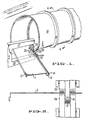
- Pipe 10 is shown during its manufacture using the present invention.
- Pipe 10 is helically formed from strip material 11 which, prior to coiling, is processed through sets of forming rolls (not shown) to provide a first side flange 12 and a channel 13 that includes a second side flange 14.
- Flange 12 and channel 13 project from the plane of the strip material to one side thereof, and flanges 12 and 14 project at supplementary angles that allow edge-abutment when the strip is coiled.
- flanges 12 and 14 project from the strip plane at substantially 90°, or right angles.
- the rib which is formed on the pipe is essentially of rectangular shape.
- Flanges 12 and 14 are preferably formed of substantially equal length so that the weld joint occurs on a spiral substantially midway between the inner circumference of the pipe and the outer circumference of the rib. This construction locates the weld on a helix where the forces that tend to separate the weld joint are essentially neutral (being in neither compression nor tension). For purposes of this application, this condition is referred to as locating the weld on the neutral axis of the pipe section.
- Fig. 3 A preferred arrangement of steps for forming flange 12, channel 13, and second flange 14, is shown in Fig. 3.
- the strip material is passed through a set of forming rolls which progressively bend the strip material without creating severe stressing or thinning at the bends. It is well understood in this art that undue thinning or excessive stressing will generally weaken the pipe that is formed.
- Strip width which is one factor that determines the diameter of the pipe, is carefully controlled in the manufacturing process; and, as shown in Sections A, B, C and D of Fig. 3, root bend 15, which forms flange 12 and root bend 16 of channel 13 are completely formed before the strip is finally trimmed to a preselected width, as shown in section E.
- Flange 14 is then formed by further bending steps as shown in sections F, G, and H.
- the deformed strip material is coiled as indicated in Fig. 1.
- the side edge of flange 12 is brought into abutting contact with the side edge of flange 14.
- One such apparatus known as Thermatool, is particularly useful for carrying out the welding process.
- the strip edges are spaced apart at the contacts forming an open V whose apex is slightly ahead of the weld point.
- High frequency current flows from one contact along the edge of the V to the apex and back along the other edge to the other contact.
- the current density is very high along both edges of the V because of which is known as “skin effect” and "proximity effect”.
- This high concentration of current preheats the edges so that they are at welding temperature when they come together at the apex.
- the manufacture of Thermatool equipment advocates the high speed of travel as being an inherent part of the welding process because it reduces the elapsed time between the contacts and the weld point.
- the heat developed along the V edges does not have time to be dissipated by conduction to cooler parts before the edges are squeezed together and welded.
- the upper roll 25 is supported from a mandrel 27 that extends within the pipe that is being formed; roll 26 is supported on an arm 28 from beneath the pipe.
- mandrel 27 and arm 28 are supported from a movable stanchion that may be raised or lowered as suggested by the arrows shown in Fig. 1. This allows the precise position of the rolls to be carefully controlled.
- the strip material may be formed with more than one rib or with ribs of varying sizes or shapes.
Landscapes
- Engineering & Computer Science (AREA)
- Mechanical Engineering (AREA)
- Rigid Pipes And Flexible Pipes (AREA)
- Shaping Of Tube Ends By Bending Or Straightening (AREA)
- Flanged Joints, Insulating Joints, And Other Joints (AREA)
- Lining Or Joining Of Plastics Or The Like (AREA)
Applications Claiming Priority (2)
| Application Number | Priority Date | Filing Date | Title |
|---|---|---|---|
| US944522 | 1986-12-22 | ||
| US06/944,522 US4763830A (en) | 1986-12-22 | 1986-12-22 | Method for welding ribbed pipe |
Publications (2)
| Publication Number | Publication Date |
|---|---|
| EP0273312A2 true EP0273312A2 (de) | 1988-07-06 |
| EP0273312A3 EP0273312A3 (de) | 1990-05-16 |
Family
ID=25481567
Family Applications (1)
| Application Number | Title | Priority Date | Filing Date |
|---|---|---|---|
| EP87118784A Withdrawn EP0273312A3 (de) | 1986-12-22 | 1987-12-17 | Verfahren zum Schweissen von gerippten Rohren |
Country Status (5)
| Country | Link |
|---|---|
| US (1) | US4763830A (de) |
| EP (1) | EP0273312A3 (de) |
| JP (1) | JPS63174785A (de) |
| AU (1) | AU8288287A (de) |
| CA (1) | CA1300695C (de) |
Cited By (2)
| Publication number | Priority date | Publication date | Assignee | Title |
|---|---|---|---|---|
| EP0343973A1 (de) * | 1988-05-25 | 1989-11-29 | Spiro Machines S.A. | Schraubennahtrohre |
| EP1740329A4 (de) * | 2004-04-12 | 2008-02-20 | Mark Vanderbeken | Verfahren zur herstellung eines kreisförmigen metalltanks |
Families Citing this family (16)
| Publication number | Priority date | Publication date | Assignee | Title |
|---|---|---|---|---|
| IL84797A (en) * | 1986-12-15 | 1993-01-14 | Montedison Spa | Production of crystalline vinyl aromatic polymers having mainly a syndiotactic structure |
| US6009912A (en) * | 1991-07-26 | 2000-01-04 | Andre; James R. | Steel pipe with integrally formed liner and method of fabricating the same |
| US5607530A (en) * | 1995-08-09 | 1997-03-04 | W.E. Hall Company | Polymer diverter system for metal pipe having an integrally formed polymer liner |
| US5980670A (en) * | 1997-12-12 | 1999-11-09 | Hall International, Llc | Method of forming a metal pipe with cuff for forming pipe joint |
| US6145732A (en) * | 1999-10-20 | 2000-11-14 | Edward A. Akins | Cylindrical helical seamed tube and method and apparatus therefore |
| US7942307B2 (en) * | 2007-09-18 | 2011-05-17 | 1272507 Alberta Ltd. | Apparatus for applying metallic cladding to interior surfaces of pipe elbows |
| US8573260B2 (en) | 2010-08-03 | 2013-11-05 | W.E. Hall Company, Inc. | Corrugated metal pipe |
| CN101966625A (zh) * | 2010-10-09 | 2011-02-09 | 苏州博恒浩科技有限公司 | 螺旋钢管焊接方法 |
| US8555932B2 (en) | 2011-12-14 | 2013-10-15 | W.E. Hall Company, Inc. | Corrugated metal pipe |
| US8991439B2 (en) | 2011-12-14 | 2015-03-31 | W.E. Hall Company, Inc. | Corrugated metal pipe |
| RU2510686C1 (ru) * | 2012-10-25 | 2014-04-10 | Российская Федерация от имени которой выступает Министерство промышленности и торговли (Минпромторг России) | Способ изготовления сварных тонкостенных конических обечаек с ребрами жесткости |
| US10781672B2 (en) | 2016-06-15 | 2020-09-22 | Chevron U.S.A. Inc. | Protective shrouds for sand control screen assemblies |
| US10767449B2 (en) * | 2016-06-15 | 2020-09-08 | Chevron U.S.A. Inc. | Protective shrouds for sand control screen assemblies |
| US10933455B2 (en) | 2016-07-07 | 2021-03-02 | Pacific Roller Die Company, Inc. | Tubular core and method |
| CN117182500A (zh) | 2018-07-11 | 2023-12-08 | 吉斯通塔系统公司 | 用于管状结构的凸缘装配的系统;将凸缘装配到管状区段的方法 |
| CN110026448B (zh) * | 2019-04-30 | 2021-08-03 | 西安理工大学 | 一体成型的螺旋加劲肋钢管及成型方法 |
Family Cites Families (10)
| Publication number | Priority date | Publication date | Assignee | Title |
|---|---|---|---|---|
| US1294465A (en) * | 1917-12-11 | 1919-02-18 | Geza Horvath | Radiator-tubing. |
| US2127943A (en) * | 1934-01-30 | 1938-08-23 | Titeflex Metal Hose Co | Method of making corrugated flexible tubes |
| US2288094A (en) * | 1939-01-28 | 1942-06-30 | Gen Motors Corp | Method of making tubing |
| US2758366A (en) * | 1951-01-02 | 1956-08-14 | Phillips Petroleum Co | Method of making flexible pipe |
| DE976000C (de) * | 1951-07-10 | 1963-01-10 | Ahlmann Carlshuette K G | Aus zwei Haelften verschweisste Blechradiatorenglieder, insbesondere aus Stahl |
| US3240177A (en) * | 1962-06-11 | 1966-03-15 | Calumet & Hecla | Method for making finned tubing |
| US3255516A (en) * | 1963-09-03 | 1966-06-14 | Ohio Crankshaft Co | Method and apparatus of producing heat exchanger tubing |
| US3656514A (en) * | 1968-09-18 | 1972-04-18 | Julian C Renfro | High reliability joint for manufacture of pipe |
| US3776448A (en) * | 1971-01-19 | 1973-12-04 | J Fay | Apparatus for continuous production of spiral pipe |
| US3722075A (en) * | 1971-01-19 | 1973-03-27 | J Fay | Method for continuous production of spiral pipe |
-
1986
- 1986-12-22 US US06/944,522 patent/US4763830A/en not_active Expired - Lifetime
-
1987
- 1987-12-17 EP EP87118784A patent/EP0273312A3/de not_active Withdrawn
- 1987-12-18 JP JP62321135A patent/JPS63174785A/ja active Pending
- 1987-12-21 AU AU82882/87A patent/AU8288287A/en not_active Abandoned
- 1987-12-21 CA CA000554908A patent/CA1300695C/en not_active Expired - Lifetime
Cited By (3)
| Publication number | Priority date | Publication date | Assignee | Title |
|---|---|---|---|---|
| EP0343973A1 (de) * | 1988-05-25 | 1989-11-29 | Spiro Machines S.A. | Schraubennahtrohre |
| WO1989011351A1 (en) * | 1988-05-25 | 1989-11-30 | Bubb, Antony, John, Allen | Improvements in helically formed tubing |
| EP1740329A4 (de) * | 2004-04-12 | 2008-02-20 | Mark Vanderbeken | Verfahren zur herstellung eines kreisförmigen metalltanks |
Also Published As
| Publication number | Publication date |
|---|---|
| JPS63174785A (ja) | 1988-07-19 |
| US4763830A (en) | 1988-08-16 |
| AU8288287A (en) | 1988-06-23 |
| CA1300695C (en) | 1992-05-12 |
| EP0273312A3 (de) | 1990-05-16 |
Similar Documents
| Publication | Publication Date | Title |
|---|---|---|
| US4763830A (en) | Method for welding ribbed pipe | |
| US2237309A (en) | Method and means for making hollow tubular members | |
| US3301992A (en) | Method for joining flat metal stock | |
| US4061264A (en) | Method for producing helical seam pipes | |
| US2216606A (en) | Method of making spiral pipe | |
| US3240177A (en) | Method for making finned tubing | |
| US3999029A (en) | Fin to tube welding by high frequency current source | |
| JPH03169427A (ja) | 熱交換チューブの形成方法と形成装置 | |
| EP0126795B1 (de) | Verfahren zur Herstellung geschweisster Rohre | |
| US3758740A (en) | Apparatus for scarfing weld beads | |
| JPS63317212A (ja) | 加工性の優れた電縫鋼管の製造方法 | |
| IL44178A (en) | Manufacture of tubular metal members of polygonal cross-section by rolling | |
| US4717065A (en) | Method for manufacturing welded pipes | |
| US1880095A (en) | Method of making tubular articles | |
| JPH08192228A (ja) | 溶接管の製造方法および装置 | |
| US4580715A (en) | Method and apparatus for making a water-tight radiator element | |
| EP0672474B1 (de) | Verfahren zur Herstellung eines Rohres aus Zink oder aus Zinklegierungen | |
| US3776448A (en) | Apparatus for continuous production of spiral pipe | |
| US4916853A (en) | Method for manufacturing welded pipes | |
| JPS6012220A (ja) | 金属チユ−ブの製造方法 | |
| JPS6056568B2 (ja) | 造管方法及びロ−ル | |
| JP2788911B2 (ja) | 薄肉電縫管の製造方法 | |
| JP2930249B2 (ja) | 内面溝付き管の製造方法 | |
| JP3074857B2 (ja) | 偏平金属管の製造方法および製造装置 | |
| JP2732935B2 (ja) | 粉粒体充填管の製造方法 |
Legal Events
| Date | Code | Title | Description |
|---|---|---|---|
| PUAI | Public reference made under article 153(3) epc to a published international application that has entered the european phase |
Free format text: ORIGINAL CODE: 0009012 |
|
| AK | Designated contracting states |
Kind code of ref document: A2 Designated state(s): AT BE CH DE ES FR GB GR IT LI LU NL SE |
|
| PUAL | Search report despatched |
Free format text: ORIGINAL CODE: 0009013 |
|
| AK | Designated contracting states |
Kind code of ref document: A3 Designated state(s): AT BE CH DE ES FR GB GR IT LI LU NL SE |
|
| STAA | Information on the status of an ep patent application or granted ep patent |
Free format text: STATUS: THE APPLICATION IS DEEMED TO BE WITHDRAWN |
|
| 18D | Application deemed to be withdrawn |
Effective date: 19900101 |