EP0273433B1 - Commutateur photoélectrique du type à réflexion - Google Patents
Commutateur photoélectrique du type à réflexion Download PDFInfo
- Publication number
- EP0273433B1 EP0273433B1 EP87119277A EP87119277A EP0273433B1 EP 0273433 B1 EP0273433 B1 EP 0273433B1 EP 87119277 A EP87119277 A EP 87119277A EP 87119277 A EP87119277 A EP 87119277A EP 0273433 B1 EP0273433 B1 EP 0273433B1
- Authority
- EP
- European Patent Office
- Prior art keywords
- light
- photoelectric switch
- wavelengths
- light emitting
- reflector
- Prior art date
- Legal status (The legal status is an assumption and is not a legal conclusion. Google has not performed a legal analysis and makes no representation as to the accuracy of the status listed.)
- Expired - Lifetime
Links
Images




Classifications
-
- G—PHYSICS
- G01—MEASURING; TESTING
- G01V—GEOPHYSICS; GRAVITATIONAL MEASUREMENTS; DETECTING MASSES OR OBJECTS; TAGS
- G01V8/00—Prospecting or detecting by optical means
- G01V8/10—Detecting, e.g. by using light barriers
- G01V8/12—Detecting, e.g. by using light barriers using one transmitter and one receiver
Definitions
- This invention relates to a reflection type photoelectric switch including a light projecting member for projecting a light beam to a reflector and a light receiving member for receiving a light beam reflected from the reflector to produce a light path, whereby an object is detected when it blocks the light path, and more particularly to an improved photoelectric switch which can precisely detect even an object having a mirror surface.
- one projecting member projects light of a first and second or a plurality of wavelengths towards the reflector on a single optical axis.
- the reflector is designed to differently reflect different wavelength lights while the light receiving element housed within the switch is so designed to sense the reflected lights at the different wavelengths, so that the detection of the object passing the light path between the light emitting means and the reflector is by the comparison between the levels of the reflected light at the respective wavelengths.
- the switch includes a housing 1, a printed circuit board 2 carrying a light emitting element 3 such as a light emitting diode and a light receiving element 4 such as a photodiode which are mounted on the board 2.
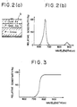
- the light emitting element 3 may employ a single light emitting diode having a GaAlAs hetero-conjunction shown in Fig. 2(a) and a spectrum characteristic wherein different wavelengths of light are emitted as shown in Fig. 2(b).
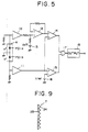
- the outputs of the pair of photodiodes PD-a and PD-b are applied to non-inverting amplifiers 10 and 11 which respectively amplify the outputs from the photodiodes at the same amplifying rate.
- the output from the amplifier 10 is applied to an adder 12 connected to a voltage source 13.
- the adder 12 sums a minute voltage level V off of the source 13 and the output from the amplifier 10, and its output is applied to the inverting input terminal of an operational amplifier representing a comparator 14.
- the output from the amplifier 11 is applied to the non-inverting input terminals of the respective operation amplifiers representing comparators 14 and 15 as comparing means.
- Table 1 The operation states at the respective portions of the photoelectric switch are represented by the following Table 1: Table 1 (I) Object non-exists (II) Ordinal object exists (III) Object having mirror surface exists Photo Current PD-a 1 0 2 PD-b 5 0 1 Comparator 14 H L L 15 H L H AND output H L L Switch output non exist exist
- the comparator 14 is "L” because the output from the diode PD-a is large, while the comparator 15 becomes “H” because the input to the non-inverting input terminal of comparator 15 is higher than the reference voltage V ref .
- the logic product from AND circuit 18 becomes “L”, and an object detection signal is produced.
- the retro-type reflector 7 in the first embodiment is constituted with combination of corner cubes made of acrylic resin absorbing red light
- the reflector 7 may be replaced by a reflector in which an infrared filter 25 passing infrared light only but blocking red light is applied on a front wall of a unit 24 consisting of transparent corner cubes, if desired, as shown in Fig. 9.
Landscapes
- Physics & Mathematics (AREA)
- Life Sciences & Earth Sciences (AREA)
- General Life Sciences & Earth Sciences (AREA)
- General Physics & Mathematics (AREA)
- Geophysics (AREA)
- Switches Operated By Changes In Physical Conditions (AREA)
- Electronic Switches (AREA)
- Geophysics And Detection Of Objects (AREA)
Claims (10)
- Interrupteur photoélectrique du type à réflexion qui détecte la présence d'un objet, comprenant:
un moyen émetteur de lumière (3, 5) émettant un faisceau lumineux sensiblement unique, ayant une première et une deuxième longueurs d'onde différentes l'une de l'autre, dans un volume dans lequel l'objet peut être détecté,
un réflecteur (7) réfléchissant ledit faisceau lumineux avec des taux de réflexion différents pour lesdites première et deuxième longueurs d'onde,
un moyen récepteur de lumière (4) pour détecter lesdites première et deuxième longueurs d'onde du faisceau lumineux réfléchi et qui produit des signaux de sortie en réponse auxdites première et deuxième longueurs d'onde, et
un moyen pour analyser lesdits signaux de sortie produits par ledit moyen de réception de lumière (4) auxdites première et deuxième longueurs d'onde pour produire un signal de sortie représentant l'existence dans ledit volume de l'objet détecté par l'interrupteur photoélectrique, caractérisé en ce que:
ledit moyen émetteur de lumière (3, 5) comprend une diode électroluminescente unique (3) qui émet de la lumière auxdites première et deuxième longueurs d'onde. - Interrupteur photoélectrique du type à réflexion conforme à la revendication 1, dans lequel ledit moyen émetteur de lumière (3, 5) comprend une lentille convergente (5).
- Interrupteur photoélectrique du type à réflexion conforme à la revendication 1 ou 2, dans lequel ledit moyen émetteur de lumière émet de la lumière à travers une fenêtre transparente unique.
- Interrupteur photoélectrique du type à réflexion conforme à l'une quelconque des revendications précédentes, dans lequel ledit moyen pour analyser lesdits signaux de sortie comprend un moyen (14, 15) pour comparer les signaux de sortie produits par ledit moyen récepteur de lumière (4).
- Interrupteur photoélectrique du type à réflexion selon l'une quelconque des revendications précédentes, dans lequel ledit réflecteur (7) possède un taux de réflexion tel que la lumière de ladite première longueur d'onde est absorbée alors que la lumière de ladite deuxième longueur d'onde est réfléchie par le réflecteur (7).
- Interrupteur photoélectrique du type à réflexion conforme à l'une quelconque des revendications précédentes, dans lequel ladite diode photoluminescente (3) émet de la lumière selon un mode pulsé.
- Interrupteur photoélectrique qui détecte la présence d'un objet, comprenant:
un moyen émetteur de lumière émettant un faisceau lumineux sensiblement unique dans un volume dans lequel l'objet est susceptible d'être détecté,
un réflecteur pour réfléchir ledit faisceau lumineux avec des taux de réflexion différents selon les différentes longueurs d'onde,
un moyen récepteur de lumière pour détecter lesdites différentes longueurs d'onde et pour recevoir la lumière réfléchie par ledit réflecteur , et qui produit des signaux de sortie en réponse auxdites différentes longueurs d'onde, et
un moyen pour traiter lesdits signaux de sortie engendrés par ledit organe récepteur de lumière afin de produire des signaux spécifiques correspondant respectivement auxdites différentes longueurs d'onde , et
un moyen pour analyser lesdits signaux spécifiques afin de distinguer si le faisceau lumineux recu est réfléchi par le réflecteur ou par un objet à détecter par l'interrupteur photoélectrique, caractérisé en ce que :
ledit moyen émetteur de lumière comprend une pastille unique formant élément émetteur de lumière dans un groupe de longueurs d'onde, et en ce que:
lesdites différentes longueurs d'onde sont constituées par ledit groupe de longueurs d'onde. - Interrupteur photoélectrique conforme à la revendication 7, dans lequel ledit moyen émetteur de lumière comprend un élément émetteur de lumière et une lentille convergente.
- Interrupteur photoélectrique conforme à la revendication 7 ou 8, dans lequel ledit moyen récepteur de lumière comprend une pastille unique d'un élément récepteur de lumière pour détecter la lumière aux longueurs d'onde dudit groupe de longueurs d'onde.
- Interrupteur photoélectrique conforme à l'une quelconque des revendications 7 à 9, dans lequel ledit élément émetteur de lumière émet de la lumière selon un mode pulsé.
Priority Applications (1)
| Application Number | Priority Date | Filing Date | Title |
|---|---|---|---|
| AT87119277T ATE80475T1 (de) | 1986-12-26 | 1987-12-28 | Photoelektrischer schalter vom reflektionstyp. |
Applications Claiming Priority (2)
| Application Number | Priority Date | Filing Date | Title |
|---|---|---|---|
| JP312456/86 | 1986-12-26 | ||
| JP61312456A JP2574780B2 (ja) | 1986-12-26 | 1986-12-26 | 反射型光電スイッチ |
Publications (3)
| Publication Number | Publication Date |
|---|---|
| EP0273433A2 EP0273433A2 (fr) | 1988-07-06 |
| EP0273433A3 EP0273433A3 (en) | 1989-11-15 |
| EP0273433B1 true EP0273433B1 (fr) | 1992-09-09 |
Family
ID=18029408
Family Applications (1)
| Application Number | Title | Priority Date | Filing Date |
|---|---|---|---|
| EP87119277A Expired - Lifetime EP0273433B1 (fr) | 1986-12-26 | 1987-12-28 | Commutateur photoélectrique du type à réflexion |
Country Status (6)
| Country | Link |
|---|---|
| US (1) | US5004908A (fr) |
| EP (1) | EP0273433B1 (fr) |
| JP (1) | JP2574780B2 (fr) |
| AT (1) | ATE80475T1 (fr) |
| DE (1) | DE3781657T2 (fr) |
| ES (1) | ES2035028T3 (fr) |
Families Citing this family (20)
| Publication number | Priority date | Publication date | Assignee | Title |
|---|---|---|---|---|
| JPH062348Y2 (ja) * | 1988-02-15 | 1994-01-19 | オムロン株式会社 | 反射型光電スイッチ |
| DE4029766A1 (de) * | 1990-09-20 | 1992-04-02 | Leuze Electronic Gmbh & Co | Reflexionslichtschranke |
| US5442168A (en) * | 1991-10-15 | 1995-08-15 | Interactive Light, Inc. | Dynamically-activated optical instrument for producing control signals having a self-calibration means |
| US5313508A (en) * | 1991-12-23 | 1994-05-17 | Batching Systems, Inc. | Method of and apparatus for detecting and counting articles |
| US5508511A (en) * | 1994-05-24 | 1996-04-16 | Interactive Light, Inc. | Arrangement for and method of detecting an object in an area subject to environmental variations |
| CN1154139C (zh) * | 1996-02-21 | 2004-06-16 | 和泉电气株式会社 | 光电开关器件及开关方法 |
| DE19627083C2 (de) * | 1996-07-05 | 2003-04-17 | Leuze Electronic Gmbh & Co | Reflexionslichtschranke |
| US5734343A (en) * | 1996-07-18 | 1998-03-31 | Motorola, Inc. | One-way optical highway communication system |
| DE19644278A1 (de) * | 1996-10-24 | 1998-05-07 | Ines Elektronik Systementwickl | Optische Schranke sowie daraus aufgebaute Überwachungseinrichtung |
| GB2342989A (en) * | 1998-10-23 | 2000-04-26 | Integrated Design Limited | Detection system |
| JP2005241340A (ja) * | 2004-02-25 | 2005-09-08 | Sharp Corp | マルチ測距装置 |
| DE102005060399A1 (de) * | 2005-12-16 | 2007-06-21 | Sick Ag | Optoelektronische Vorrichtung und Verfahren zum Betreiben einer optoelektronischen Vorrichtung |
| JP2009177721A (ja) * | 2008-01-28 | 2009-08-06 | Sharp Corp | 物体検出回路及びそれを備えた物体検出装置 |
| KR101352117B1 (ko) * | 2009-10-22 | 2014-01-14 | 엘지디스플레이 주식회사 | 터치 패널을 갖는 표시 장치 및 이의 터치 감지 방법 |
| DE102010012712A1 (de) * | 2010-03-25 | 2011-09-29 | Osram Opto Semiconductors Gmbh | Licht emittierendes Halbleiterbauteil |
| US9046964B2 (en) * | 2011-10-27 | 2015-06-02 | Beijing Irtouch Systems Co., Ltd | Frame component for infrared touch screen and infrared touch screen |
| US10634813B2 (en) * | 2015-05-18 | 2020-04-28 | Lasermotive, Inc. | Multi-layered safety system |
| DE102015111379A1 (de) * | 2015-07-14 | 2017-01-19 | Sick Ag | Optoelektronischer Sensor |
| US10393918B2 (en) * | 2017-03-28 | 2019-08-27 | Banner Engineering Corp. | Retro-reflective sensor with multiple detectors |
| JP6985329B2 (ja) * | 2019-05-15 | 2021-12-22 | 矢崎総業株式会社 | 発光装置 |
Family Cites Families (12)
| Publication number | Priority date | Publication date | Assignee | Title |
|---|---|---|---|---|
| US3944818A (en) * | 1972-03-28 | 1976-03-16 | Visomat-Gerate Gmbh | Photoelectric guard |
| FR2442457A1 (fr) * | 1978-11-27 | 1980-06-20 | Optel | Dispositif photoelectrique a double faisceau et systeme reflechissant selectif |
| DE2941739C2 (de) * | 1979-10-16 | 1982-02-18 | Krohne Meßtechnik GmbH & Co KG, 4100 Duisburg | Lichtgitter |
| US4433328A (en) * | 1980-01-16 | 1984-02-21 | Saphir Marc E | Motion sensing energy controller |
| JPS57178535A (en) * | 1981-04-29 | 1982-11-02 | Mitsubishi Electric Corp | Process signal input equipment |
| DE3237035C1 (de) * | 1982-10-06 | 1984-01-26 | Erwin Sick Gmbh Optik-Elektronik, 7808 Waldkirch | Reflexionslichtschranke |
| JPS59119628A (ja) * | 1982-12-25 | 1984-07-10 | オムロン株式会社 | 反射形光電スイツチ |
| JPS6196626A (ja) * | 1984-10-16 | 1986-05-15 | オムロン株式会社 | 反射形光電スイツチ |
| FR2574200B1 (fr) * | 1984-11-30 | 1987-01-23 | Labo Electronique Physique | Dispositif de detection d'intrus muni d'un dispositif d'antimasquage |
| DE3447131A1 (de) * | 1984-12-22 | 1986-06-26 | Telenot Electronic GmbH, 7080 Aalen | Raumschutzanlage |
| US4564085A (en) * | 1985-01-22 | 1986-01-14 | Towmotor Corporation | Controlling arrangement |
| US4658147A (en) * | 1985-04-03 | 1987-04-14 | Baird Corporation | Remote optically readable system and method |
-
1986
- 1986-12-26 JP JP61312456A patent/JP2574780B2/ja not_active Expired - Lifetime
-
1987
- 1987-12-28 ES ES198787119277T patent/ES2035028T3/es not_active Expired - Lifetime
- 1987-12-28 AT AT87119277T patent/ATE80475T1/de active
- 1987-12-28 EP EP87119277A patent/EP0273433B1/fr not_active Expired - Lifetime
- 1987-12-28 US US07/138,052 patent/US5004908A/en not_active Expired - Fee Related
- 1987-12-28 DE DE8787119277T patent/DE3781657T2/de not_active Expired - Fee Related
Also Published As
| Publication number | Publication date |
|---|---|
| US5004908A (en) | 1991-04-02 |
| JPS63166118A (ja) | 1988-07-09 |
| ATE80475T1 (de) | 1992-09-15 |
| EP0273433A2 (fr) | 1988-07-06 |
| JP2574780B2 (ja) | 1997-01-22 |
| ES2035028T3 (es) | 1993-04-16 |
| DE3781657T2 (de) | 1993-03-18 |
| DE3781657D1 (de) | 1992-10-15 |
| EP0273433A3 (en) | 1989-11-15 |
Similar Documents
| Publication | Publication Date | Title |
|---|---|---|
| US5004908A (en) | Reflection type photoelectric switch for detecting the presence of an object | |
| US5008529A (en) | Photoelectric switching apparatus of reflection type projecting red and infrared light | |
| EP2535742A2 (fr) | Système et procédé de réduction de bruit optique | |
| KR20210096243A (ko) | 라이다 시스템 및 자동차 | |
| EP0926646B8 (fr) | Détecteur de fumée optique | |
| JPS60158309A (ja) | 距離検出装置 | |
| US6414773B1 (en) | Optical digital communication apparatus | |
| FR2442457A1 (fr) | Dispositif photoelectrique a double faisceau et systeme reflechissant selectif | |
| EP0675376A4 (fr) | Capteur de faisceau lumineux a axes optiques multiples et surete integree. | |
| CN214623250U (zh) | 一种三维相机及3d探测设备 | |
| JPH04260197A (ja) | 光電式煙感知器 | |
| JP2638959B2 (ja) | 回帰反射型光電スイッチ | |
| US12196584B2 (en) | Multi-track optical encoder | |
| JPH0531584Y2 (fr) | ||
| JPH06132802A (ja) | 多光軸光電スイッチ | |
| JPS6446242A (en) | Optical pickup | |
| JPS59119628A (ja) | 反射形光電スイツチ | |
| JPS63309881A (ja) | 車両用障害物検出装置 | |
| JPS57204482A (en) | Reflection type photoelectric switch | |
| JPH03131790A (ja) | 車両用障害物検知装置 | |
| CN119156785A (zh) | 机动车辆的包括用于接收光束的模块的检测和/或通信系统 | |
| JPH05274967A (ja) | 光電スイッチ | |
| JPH06111693A (ja) | リフレクタ形光電スイッチ | |
| JPS62261221A (ja) | 反射式光電スイツチ | |
| JPH073584A (ja) | 織機の緯糸検出装置 |
Legal Events
| Date | Code | Title | Description |
|---|---|---|---|
| PUAI | Public reference made under article 153(3) epc to a published international application that has entered the european phase |
Free format text: ORIGINAL CODE: 0009012 |
|
| 17P | Request for examination filed |
Effective date: 19871228 |
|
| AK | Designated contracting states |
Kind code of ref document: A2 Designated state(s): AT BE CH DE ES FR GB GR IT LI LU NL SE |
|
| PUAL | Search report despatched |
Free format text: ORIGINAL CODE: 0009013 |
|
| AK | Designated contracting states |
Kind code of ref document: A3 Designated state(s): AT BE CH DE ES FR GB GR IT LI LU NL SE |
|
| 17Q | First examination report despatched |
Effective date: 19910321 |
|
| GRAA | (expected) grant |
Free format text: ORIGINAL CODE: 0009210 |
|
| AK | Designated contracting states |
Kind code of ref document: B1 Designated state(s): AT BE CH DE ES FR GB GR IT LI LU NL SE |
|
| PG25 | Lapsed in a contracting state [announced via postgrant information from national office to epo] |
Ref country code: SE Effective date: 19920909 Ref country code: GR Free format text: LAPSE BECAUSE OF FAILURE TO SUBMIT A TRANSLATION OF THE DESCRIPTION OR TO PAY THE FEE WITHIN THE PRESCRIBED TIME-LIMIT Effective date: 19920909 |
|
| REF | Corresponds to: |
Ref document number: 80475 Country of ref document: AT Date of ref document: 19920915 Kind code of ref document: T |
|
| ITF | It: translation for a ep patent filed | ||
| REF | Corresponds to: |
Ref document number: 3781657 Country of ref document: DE Date of ref document: 19921015 |
|
| ET | Fr: translation filed | ||
| PG25 | Lapsed in a contracting state [announced via postgrant information from national office to epo] |
Ref country code: LU Free format text: LAPSE BECAUSE OF NON-PAYMENT OF DUE FEES Effective date: 19921231 |
|
| REG | Reference to a national code |
Ref country code: ES Ref legal event code: FG2A Ref document number: 2035028 Country of ref document: ES Kind code of ref document: T3 |
|
| PLBE | No opposition filed within time limit |
Free format text: ORIGINAL CODE: 0009261 |
|
| STAA | Information on the status of an ep patent application or granted ep patent |
Free format text: STATUS: NO OPPOSITION FILED WITHIN TIME LIMIT |
|
| 26N | No opposition filed | ||
| PGFP | Annual fee paid to national office [announced via postgrant information from national office to epo] |
Ref country code: ES Payment date: 19951213 Year of fee payment: 9 |
|
| PGFP | Annual fee paid to national office [announced via postgrant information from national office to epo] |
Ref country code: NL Payment date: 19951219 Year of fee payment: 9 Ref country code: CH Payment date: 19951219 Year of fee payment: 9 Ref country code: AT Payment date: 19951219 Year of fee payment: 9 |
|
| PGFP | Annual fee paid to national office [announced via postgrant information from national office to epo] |
Ref country code: BE Payment date: 19960109 Year of fee payment: 9 |
|
| PG25 | Lapsed in a contracting state [announced via postgrant information from national office to epo] |
Ref country code: AT Effective date: 19961228 |
|
| PG25 | Lapsed in a contracting state [announced via postgrant information from national office to epo] |
Ref country code: ES Free format text: LAPSE BECAUSE OF NON-PAYMENT OF DUE FEES Effective date: 19961230 |
|
| PG25 | Lapsed in a contracting state [announced via postgrant information from national office to epo] |
Ref country code: LI Effective date: 19961231 Ref country code: CH Effective date: 19961231 Ref country code: BE Effective date: 19961231 |
|
| BERE | Be: lapsed |
Owner name: OMRON TATEISI ELECTRONICS CO. Effective date: 19961231 |
|
| PG25 | Lapsed in a contracting state [announced via postgrant information from national office to epo] |
Ref country code: NL Effective date: 19970701 |
|
| REG | Reference to a national code |
Ref country code: CH Ref legal event code: PL |
|
| NLV4 | Nl: lapsed or anulled due to non-payment of the annual fee |
Effective date: 19970701 |
|
| PGFP | Annual fee paid to national office [announced via postgrant information from national office to epo] |
Ref country code: GB Payment date: 19981118 Year of fee payment: 12 |
|
| PGFP | Annual fee paid to national office [announced via postgrant information from national office to epo] |
Ref country code: FR Payment date: 19981222 Year of fee payment: 12 |
|
| PGFP | Annual fee paid to national office [announced via postgrant information from national office to epo] |
Ref country code: DE Payment date: 19981231 Year of fee payment: 12 |
|
| PG25 | Lapsed in a contracting state [announced via postgrant information from national office to epo] |
Ref country code: GB Free format text: LAPSE BECAUSE OF NON-PAYMENT OF DUE FEES Effective date: 19991228 |
|
| GBPC | Gb: european patent ceased through non-payment of renewal fee |
Effective date: 19991228 |
|
| PG25 | Lapsed in a contracting state [announced via postgrant information from national office to epo] |
Ref country code: FR Free format text: LAPSE BECAUSE OF NON-PAYMENT OF DUE FEES Effective date: 20000831 |
|
| PG25 | Lapsed in a contracting state [announced via postgrant information from national office to epo] |
Ref country code: DE Free format text: LAPSE BECAUSE OF NON-PAYMENT OF DUE FEES Effective date: 20001003 |
|
| REG | Reference to a national code |
Ref country code: FR Ref legal event code: ST |
|
| REG | Reference to a national code |
Ref country code: ES Ref legal event code: FD2A Effective date: 19980113 |
|
| PG25 | Lapsed in a contracting state [announced via postgrant information from national office to epo] |
Ref country code: IT Free format text: LAPSE BECAUSE OF NON-PAYMENT OF DUE FEES;WARNING: LAPSES OF ITALIAN PATENTS WITH EFFECTIVE DATE BEFORE 2007 MAY HAVE OCCURRED AT ANY TIME BEFORE 2007. THE CORRECT EFFECTIVE DATE MAY BE DIFFERENT FROM THE ONE RECORDED. Effective date: 20051228 |