EP0273671A2 - Ensemble de masquage - Google Patents
Ensemble de masquage Download PDFInfo
- Publication number
- EP0273671A2 EP0273671A2 EP87311258A EP87311258A EP0273671A2 EP 0273671 A2 EP0273671 A2 EP 0273671A2 EP 87311258 A EP87311258 A EP 87311258A EP 87311258 A EP87311258 A EP 87311258A EP 0273671 A2 EP0273671 A2 EP 0273671A2
- Authority
- EP
- European Patent Office
- Prior art keywords
- shutter
- leaves
- leaf
- apertures
- aperture
- Prior art date
- Legal status (The legal status is an assumption and is not a legal conclusion. Google has not performed a legal analysis and makes no representation as to the accuracy of the status listed.)
- Withdrawn
Links
Images






Classifications
-
- G—PHYSICS
- G01—MEASURING; TESTING
- G01N—INVESTIGATING OR ANALYSING MATERIALS BY DETERMINING THEIR CHEMICAL OR PHYSICAL PROPERTIES
- G01N21/00—Investigating or analysing materials by the use of optical means, i.e. using sub-millimetre waves, infrared, visible or ultraviolet light
- G01N21/17—Systems in which incident light is modified in accordance with the properties of the material investigated
- G01N21/25—Colour; Spectral properties, i.e. comparison of effect of material on the light at two or more different wavelengths or wavelength bands
- G01N21/251—Colorimeters; Construction thereof
- G01N21/253—Colorimeters; Construction thereof for batch operation, i.e. multisample apparatus
-
- G—PHYSICS
- G02—OPTICS
- G02B—OPTICAL ELEMENTS, SYSTEMS OR APPARATUS
- G02B5/00—Optical elements other than lenses
- G02B5/005—Diaphragms
-
- G—PHYSICS
- G01—MEASURING; TESTING
- G01N—INVESTIGATING OR ANALYSING MATERIALS BY DETERMINING THEIR CHEMICAL OR PHYSICAL PROPERTIES
- G01N2201/00—Features of devices classified in G01N21/00
- G01N2201/04—Batch operation; multisample devices
- G01N2201/0446—Multicell plate, sequential
Definitions
- This invention relates to a shutter assembly for selectively allowing fluid or radiation such as light through an aperture positioned at a selected aperture position chosen out of a plurality of potential aperture positions.
- a microtitration plate is a tray containing a large number of small test tubes, known as wells, which are used for testing purposes in biochemical and allied fields.
- a commonly used microtitration plate comprises 96 wells in an array of 12 x 8.
- the wells indeed the whole plate, are usually made of plastics material and the wells may be opaque or transparent, depending upon the particular test to be performed. Many of the tests carried out in the wells rely on measuring the light emitted by the well. The light may either be generated within the well itself, as in luminescent testing, or may be passed through the well from an external light source, as in optical density testing. In the former case, the wells are made of opaque material, in the latter case, of transparent material.
- the whole object of the microtitration plate is to enable many tests to be carried out simultaneously, a need arises for obtaining and measuring the light output from just one well, and blocking the remainder, so that the result of the test in that one well can be ascertained. It is necessary to cycle around all of the wells, one by one, and measure the light output from each in turn.
- the shutter assembly of the present invention is able to allow selection of just a single well to monitor, to the exclusion of all the others.
- the shutter assembly comprises a plurality of parallel shutter leaves and means for sliding each said shutter leaf relative to the remainder and wherein each shutter leaf is formed with a pattern of apertures arranged in such a way as to align with certain apertures in other shutter leaves so that, for at least some positions of each shutter leaf at least one aperture in each shutter leaf is in alignment to thereby provide at least one through-aperture from one side of the shutter to the other.
- each shutter leaf is constructed to move between just two fixed positions, each of which positions can be represented as logical "0" or logical "1".
- a pattern of apertures for each leaf and corresponding movement can then be worked out to provide the necessary end result: namely that any one set of leaf positions provides a through aperture at a unique position.
- the minimum number of shutter leaves necessary will be dictated by the number of required aperture positions: 2 leaves will give the potential for up to 22 or 4 aperture positions; 3 leaves will give 23; 4 leaves will give 24, and so on.
- a typical array of 12 x 8 or 96 wells will require 7 shutter leaves giving a potential 27 or 128 aperture positions.
- the pattern of apertures on each leaf must be carefully selected.
- One particular method, for the binary system, is described herein.
- the pattern of apertures is organised in such a way that every leaf moves an identical distance.
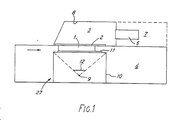
- Figure 1 shows a reader for analysing the result of reactions going on in the wells in a microtitration tray 1.
- the tray has a total of 96 wells arranged in a 12 x 8 array.
- a shutter assembly 2 which is arranged to block off the light output from all but a selected one of the wells.
- Light from the chosen well passes into a light integrating enclosure 3 from where it passes to a photo-multiplier tube (PMT) or solid state photodiode detector.
- PMT photo-multiplier tube
- Associated electronic circuitry (not shown) within enclosures 6 and (if needed) 7 amplifies and processes the output from detector 5 to indicate the results of the reaction.
- the integrating enclosure 3 is shaped as shown to reduce the surface area of enclosure 3 so as to approximate to a true integrating enclosure.
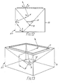
- the internal surface 8 of enclosure 3 is coated with a diffusing and highly (>98%) reflecting coating shown in greater detail in Figures 12 and 13.
- the illuminator comprises a light source 9 such as a constant-current driven LED, or a radioactively driven light source, within a light integrating box 10.
- the box 10 is for convenience rectangular in shape and is coated on its inside surface with a diffusing and highly reflective coating, as above.
- the top surface of the box forms the light outlet aperture and is covered with a scattering plate 11, for example of ground glass.
- a baffle 12 is fitted just above the light source and is arranged so as to cast a shadow right across the outlet aperture so that no direct light from the source 9 is able to pass through the plate 11.
- FIG. 14 An alternative form of illuminator is shown in Figure 14, and comprises an enclosure 13 having a light source 9 and output aperture covered by a scattering plate 11, for example of ground glass.
- the enclosure is shaped in such a way that all optical paths 14 from the source 9 to the plate 11 are of equal length.
- the rectangular-section right hand end 15 of the enclosure is blackened to reduce reflection; the surface 16 opposite the source takes the form of part of a parabolic mirror whose focus is at the light source.
- the triangular-section area 17, which are blackened, are in order to prevent direct illumination of the output aperture by the source.
- the uniform illuminator 27 of whatever form, may act as a light source during optical density testing, but its main purpose is for calibration purposes. To this end, it will be appreciated that the integrating enclosure 3 is not perfect which means that wells in different positions in the microtitration tray will differently illuminate the detector 5. To compensate for this the uniform illuminator may be used to individually test the well positions, without any sample present, store the result and then apply an appropriate factor to the proper sample test result received from each well.
- the calibration tests may be carried out by an associated computer (not shown) and is preferably done automatically and constantly throughout the time that the machine is switched on by cycling around the individual wells by means of the shutter assembly, to be described, and monitoring and storing the result.
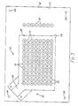
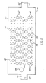
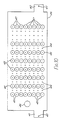
- the shutter assembly 2 is shown in detail in Figures 2 to 11.
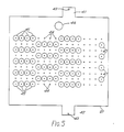
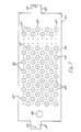
- FIG. 1 Each of Figures 3 to 11 of the drawings show a component of the assembly.
- the assembly comprises a bottom plate 18 (Figure 2) and top plate 19 (Figure 11) between which are sandwiched seven shutter leaves 20 to 26 ( Figures 4 to 10) which are slidable with respect to one another.
- the bottom plate comprises a 1.2 cm thick aluminium alloy plate 27 having a generally rectangular portion 28 cut out from its underside to give a material thickness of 1 mm.
- This rectangular cut-out portion provides a secure location for the microtitration plate 1 which, in use of the apparatus, is located, wells uppermost, within the rectangular portion 28 and pushed firmly against the material of the plate 27 by virtue of being sandwiched between this and the scattering plate 11 of the illuminator 27.
- a roller assembly 29 or other means may be used to push the microtitration plate 1 into the registration corner 30 of the portion 28 as the microtitration plate is raised into the portion 28 (arrow A, Figure 2).
- the material forming the top of cut-out portion 28 is provided with a plurality of 7.5 mm diameter apertures 31, each in registry with a single well within the microtitration plate 1.
- a further eight apertures 32 are provided to the side of the cut-out portion 28 for calibration purposes.
- Two 3 mm diameter holes 33 are provided to locate pins, also 3 mm in diameter, which pass between the top and bottom plates and through the shutter leaves.
- a hole 34 is formed in each corner to receive the shank of a respective bolt (not shown) for holding the assembly together.
- the top plate 19 is formed of a sheet 35 of 1.5 mm thick aluminium alloy and is of similar shape and dimensions to the bottom plate. Holes 36 are formed in the corners of the plate 19 in registry with holes 34 in the bottom plate so that the two plates can be attached together by means of bolts. Each corner area 37 of the sheet 35 is formed with a 5 mm thick upstanding portion, shown in dotted outline, to thereby define a 3.5 mm thick separation between the top and bottom plates.
- a rectangular aperture 38 is formed in the sheet 35 in registry with the cut-out portion 28 of the bottom plate.
- a further rectangular aperture 39 overlies the group of apertures 32 in the bottom plate, and a pair of 3mm diameter holes 40 are in regustry with holes 33 to mount the other end of the aformentioned pins.
- Each of the shutter leaves 20 to 26 is formed from a 0.5 mm thick aluminium sheet which is blackened to reduce light leakage between apertures.
- the sheet is formed with a pair of oppositely-disposed lugs 41, 42 having holes 43 for the attachment of a pull wire (not shown) linked to an associated solenoid.
- each shutter leaf is associated with two solenoids.
- Each sheet is marked on the drawings with a plurality of potential aperture positions. These positions are marked with a plus sign, such as at 44. At some of these apertures positions an aperture 45 of 1 mm greater diameter than apertures 31 is formed to make up an aperture pattern, different for each leaf.
- the seven leaves are divided into two groups according to their direction of movement: the leaves 20 to 22 are constrained to slide in the vertical direction in Figure 11; the leaves 23 to 26 are constrained to slide in the horizontal direction in Figure 11.
- the leaves 20 to 22 will be referred to as the Y-axis leaves, while the leaves 23 to 26 will be referred to as the X-axis leaves.
- the leaves slide against the appropriate facing edges of the upstanding corner areas 37 on the top sheet 35.
- Movement of the leaves is effected by the aformentioned solenoids, operably attached to the lugs 41, 42.
- movement is limited by the presence of the 3 mm pins which extend between the holes 33,40 in the bottom and top plates.
- One of these pins extends through a 12 mm diameter aperture 46 formed in each leaf: the uppermost pin in Figure 11 passes through the aperture 46 in the Y-axis leaves 20 to 24; the leftmost pin in Figure 11 passes through the aperture 46 in the X-axis leaves 25 and 26.
- the leaves are thus capable only of movement corresponding to movement of the appropriate 3 mm pin passing across the diameter of the corresponding aperture 46.
- With a pin size of 3 mm and aperture size of 12 mm the maximum movement of the leaves is 9 mm which is the pitch between adjacent wells in the titration plate 1. This same pitch is used for the aperture locations 44.
- the solenoids are such as to move the leaves by the maximum extent possible.
- one of the solenoids for that leaf is energised to slide the leaf, relative to the others, to one limit position. If it is desired to move the leaf to the other limit position, the other solenoid is energised. Once the solenoid has moved the leaf to its limit position, it is de-energised; inter-leaf friction avoids the need to maintain energisation to hold the leaf in position.
- the arrangement is such that, at each limit position, at least some of the aperture locations 44 in each leaf are in registry with corresponding apertures 31 in the bottom plate 18 and hence with the wells.
- the apertures 45 in each plate are arranged, with respect to the aperture locations 44, in distinct groups.
- the number of apertures in each group is a power of two: 20, 21, 22, 23, and so on, for each leaf.
- Leaf 22 : 23 8
- the spacing between the apertures is as follows: in the direction of movement of the leaf, the pattern for any one line must be alternate apertures and spaces - i.e. aperture - space - aperture - space - aperture etc. In the direction at right angles to the direction of movement the pattern is again alternate, but this time by group - for example in the "21" shutter leaf where there are two apertures in each group, the pattern is 2 apertures alternating with 2 spaces.
- the apertures of a group for any one leaf of a particular axis will cover half of the apertures in a group of the next higher order leaf.
- the zeroth order (20) leaf is the least significant leaf for each axis while the highest order leaf is the most significant leaf for each axis.
- the shutters can be addressed via their respective solenoids by means of a 7-bit word, giving 27 or 128 possible aperture positions, of which 96 are used in this particular application.
- auxiliary apertures 47 In addition to the main apertures 45 in each leaf, there are a number of auxiliary apertures 47 associated with a number of calibration light sources (not shown) positioned under the shutter arrangement behind respective apertures 32 in the bottom plate.
- a total of fourteen solenoids are used to actuate the shutter leaves and, in binary terminology the solenoids of each leaf may be referred to respectively as the logic 0 and logic 1 solenoids.
- the shutter leaves may be slid from end to end and allowed to rest in their selected positions with the solenoids de-energised. This minimises power supply loading, and hence heat generation is small, and also means that the detector 5 will not require shielding against their stray magnetic fields. Inter-leaf friction is used to prevent unwanted movement of the leaves.
- the associated computer can be used to control the movement of the shutter leaves both during the duration of an actual test on a microtitration tray, or during calibration. It will be seen that it can be readily arranged that the computer carries out calibration measurements at all times that an actual test is not being carried out. This means that, once the initial warm-up period is over, the apparatus is constantly ready for measurements to be taken and will apply to those measurements correction factors based on the stored values from the immediately preceding calibration measurements.
- the objective of the multi leaf shutter system is to achieve positional scanning of a matrix of sources, without needing precise extended X-Y movement of either the source matrix or the detector input aperture.
- the device consists of a multiplicity of leaf shutters, each with a specific configuration of apertures such that in any position of the shutters only a unique coincidence of apertures allows the detector to 'see' an individual source.
- the shutter leaves will be moved by means of solenoids or other means of converting binary data output from an electronic controller into the required mechanical movement.
- This data may be scanned in any sequence (Binary, Gray or randomly) that is convenient for the application; the time taken to move from any position exposed to any other position exposed is merely the time to change shutter positions, unlike an X-Y mechanism which physically travels between positions.
- the shutter leaf orders must include the whole matrix, e.g. for a 12 x 8 matrix the shutter leaves will have to define a 16 x 8 (27 or 128) matrix.
- the unused positions have been exploited in the above described design for 'no source' or 'calibration' positions.
Landscapes
- Physics & Mathematics (AREA)
- General Physics & Mathematics (AREA)
- Optics & Photonics (AREA)
- Spectroscopy & Molecular Physics (AREA)
- Health & Medical Sciences (AREA)
- Life Sciences & Earth Sciences (AREA)
- Chemical & Material Sciences (AREA)
- Analytical Chemistry (AREA)
- Biochemistry (AREA)
- General Health & Medical Sciences (AREA)
- Immunology (AREA)
- Pathology (AREA)
- Particle Accelerators (AREA)
- Radiation-Therapy Devices (AREA)
- Automatic Analysis And Handling Materials Therefor (AREA)
- Investigating Or Analysing Materials By Optical Means (AREA)
Applications Claiming Priority (2)
| Application Number | Priority Date | Filing Date | Title |
|---|---|---|---|
| GB8631084 | 1986-12-31 | ||
| GB868631084A GB8631084D0 (en) | 1986-12-31 | 1986-12-31 | Shutter assembly |
Publications (2)
| Publication Number | Publication Date |
|---|---|
| EP0273671A2 true EP0273671A2 (fr) | 1988-07-06 |
| EP0273671A3 EP0273671A3 (fr) | 1990-06-06 |
Family
ID=10609711
Family Applications (1)
| Application Number | Title | Priority Date | Filing Date |
|---|---|---|---|
| EP87311258A Withdrawn EP0273671A3 (fr) | 1986-12-31 | 1987-12-21 | Ensemble de masquage |
Country Status (3)
| Country | Link |
|---|---|
| EP (1) | EP0273671A3 (fr) |
| JP (1) | JPS63175743A (fr) |
| GB (1) | GB8631084D0 (fr) |
Cited By (4)
| Publication number | Priority date | Publication date | Assignee | Title |
|---|---|---|---|---|
| EP0523521A3 (en) * | 1991-07-18 | 1994-09-14 | Berthold Lab Prof Dr | Radiation measuring apparatus, in particular for measuring the luminescence |
| WO2000004388A3 (fr) * | 1998-07-15 | 2000-06-29 | Lionheart Technologies Inc | Methode de quantification et d'etablissement de valeurs estimatives de l'activation plaquettaire, methode de controle du dosage d'agents pharmaceutiques antiplaquettaires et d'adaptation de ce dosage |
| US6111636A (en) * | 1998-04-17 | 2000-08-29 | Labsystems Oy | Device for measuring optical density |
| EP1239665A3 (fr) * | 2001-03-09 | 2004-01-21 | BODENSEEWERK GERÄTETECHNIK GmbH | Arrangement de diafragmes pour un système micro-optique |
Families Citing this family (1)
| Publication number | Priority date | Publication date | Assignee | Title |
|---|---|---|---|---|
| JP7725354B2 (ja) * | 2021-12-15 | 2025-08-19 | 株式会社東芝 | 配管型撹拌造粒ユニットおよび配管型撹拌造粒固液分離装置 |
Family Cites Families (4)
| Publication number | Priority date | Publication date | Assignee | Title |
|---|---|---|---|---|
| USRE31478E (en) * | 1977-08-02 | 1983-12-27 | R. J. Reynolds Tobacco Company | Rotary beam chopper and scanning system |
| JPS5781220A (en) * | 1980-11-10 | 1982-05-21 | Asahi Optical Co Ltd | Diaphragm structure body for zoom lens |
| US4358203A (en) * | 1980-12-10 | 1982-11-09 | Becton Dickinson And Company | Apparatus for analyzing and evaluating tests in a plurality of wells |
| US4397560A (en) * | 1981-04-23 | 1983-08-09 | Bio-Tek Instruments, Inc. | Photometer with microtray well position indicator |
-
1986
- 1986-12-31 GB GB868631084A patent/GB8631084D0/en active Pending
-
1987
- 1987-12-21 EP EP87311258A patent/EP0273671A3/fr not_active Withdrawn
- 1987-12-26 JP JP33187087A patent/JPS63175743A/ja active Pending
Cited By (5)
| Publication number | Priority date | Publication date | Assignee | Title |
|---|---|---|---|---|
| EP0523521A3 (en) * | 1991-07-18 | 1994-09-14 | Berthold Lab Prof Dr | Radiation measuring apparatus, in particular for measuring the luminescence |
| US6111636A (en) * | 1998-04-17 | 2000-08-29 | Labsystems Oy | Device for measuring optical density |
| WO2000004388A3 (fr) * | 1998-07-15 | 2000-06-29 | Lionheart Technologies Inc | Methode de quantification et d'etablissement de valeurs estimatives de l'activation plaquettaire, methode de controle du dosage d'agents pharmaceutiques antiplaquettaires et d'adaptation de ce dosage |
| US6391568B1 (en) | 1998-07-15 | 2002-05-21 | Lionheart Technologies, Inc. | Method for determining platelet reactivity in a whole blood sample |
| EP1239665A3 (fr) * | 2001-03-09 | 2004-01-21 | BODENSEEWERK GERÄTETECHNIK GmbH | Arrangement de diafragmes pour un système micro-optique |
Also Published As
| Publication number | Publication date |
|---|---|
| EP0273671A3 (fr) | 1990-06-06 |
| JPS63175743A (ja) | 1988-07-20 |
| GB8631084D0 (en) | 1987-02-04 |
Similar Documents
| Publication | Publication Date | Title |
|---|---|---|
| EP0910791B1 (fr) | Systeme d'imagerie ameliore pour analyses par fluorescence | |
| EP1043580B1 (fr) | Appareil d'éclairage avec spot linéaire | |
| NL8202698A (nl) | Inrichting voor het optisch aftasten van een document. | |
| AU2007302243B2 (en) | Apparatus and method for optical analysis of value documents | |
| JPH01503751A (ja) | 書類照射装置 | |
| TW201638555A (zh) | 用於產生圖形照明的設備 | |
| EP0273671A2 (fr) | Ensemble de masquage | |
| US20040004759A1 (en) | Microscope array for simultaneously imaging multiple objects | |
| EP0424359A2 (fr) | Dispositif pour émettre des plans lumineux | |
| EP0114914A1 (fr) | Dispositif pour détecter et évaluer des bandes de mesure colorimétriques sur une feuille d'impression | |
| US7136087B2 (en) | Multi-exposure drawing method and apparatus therefor | |
| WO1997033140A1 (fr) | Dispositif et procede pour explorer optiquement des surfaces | |
| US3791275A (en) | Multiple image formation through self-imaging | |
| DE60029271T9 (de) | Kalibriersystem und -verfahren für ein Bilderzeugungsgerät | |
| EP0100610B1 (fr) | Système d'illumination | |
| JPH10213635A (ja) | 放射分布検出用顕微鏡システム及びその操作方法 | |
| WO2009037708A2 (fr) | Codage de porteur de cellules | |
| US3324294A (en) | Collimator for eliminating internal reflections comprising a plurality of aligned aperture arrays | |
| US12130475B2 (en) | Secondary grid plates for optical switching applications | |
| KR900018745A (ko) | 자외광조사프로젝터 및 광학적 상형성장치 | |
| WO2016142153A1 (fr) | Unité d'éclairement de balayage de pathologie numérique | |
| DE4308456A1 (de) | Vorrichtung zur Lagebestimmung eines Positionierkörpers relativ zu einem Bezugskörper | |
| CN112611457B (zh) | 一种双光源多样本的荧光检测光学系统、工作方法、应用 | |
| US4751522A (en) | Photoplotter mounting head assembly | |
| US4748456A (en) | Photoplotter focus method |
Legal Events
| Date | Code | Title | Description |
|---|---|---|---|
| PUAI | Public reference made under article 153(3) epc to a published international application that has entered the european phase |
Free format text: ORIGINAL CODE: 0009012 |
|
| AK | Designated contracting states |
Kind code of ref document: A2 Designated state(s): AT BE CH DE FR GB IT LI LU NL SE |
|
| PUAL | Search report despatched |
Free format text: ORIGINAL CODE: 0009013 |
|
| AK | Designated contracting states |
Kind code of ref document: A3 Designated state(s): AT BE CH DE FR GB IT LI LU NL SE |
|
| STAA | Information on the status of an ep patent application or granted ep patent |
Free format text: STATUS: THE APPLICATION IS DEEMED TO BE WITHDRAWN |
|
| 18D | Application deemed to be withdrawn |
Effective date: 19900702 |