EP0274083B1 - Begasungs/Flotationsreaktor - Google Patents
Begasungs/Flotationsreaktor Download PDFInfo
- Publication number
- EP0274083B1 EP0274083B1 EP87118371A EP87118371A EP0274083B1 EP 0274083 B1 EP0274083 B1 EP 0274083B1 EP 87118371 A EP87118371 A EP 87118371A EP 87118371 A EP87118371 A EP 87118371A EP 0274083 B1 EP0274083 B1 EP 0274083B1
- Authority
- EP
- European Patent Office
- Prior art keywords
- tube
- foam
- liquid
- foam tube
- reactor according
- Prior art date
- Legal status (The legal status is an assumption and is not a legal conclusion. Google has not performed a legal analysis and makes no representation as to the accuracy of the status listed.)
- Expired - Lifetime
Links
Images
Classifications
-
- B—PERFORMING OPERATIONS; TRANSPORTING
- B03—SEPARATION OF SOLID MATERIALS USING LIQUIDS OR USING PNEUMATIC TABLES OR JIGS; MAGNETIC OR ELECTROSTATIC SEPARATION OF SOLID MATERIALS FROM SOLID MATERIALS OR FLUIDS; SEPARATION BY HIGH-VOLTAGE ELECTRIC FIELDS
- B03D—FLOTATION; DIFFERENTIAL SEDIMENTATION
- B03D1/00—Flotation
- B03D1/14—Flotation machines
- B03D1/24—Pneumatic
- B03D1/26—Air lift machines
-
- A—HUMAN NECESSITIES
- A01—AGRICULTURE; FORESTRY; ANIMAL HUSBANDRY; HUNTING; TRAPPING; FISHING
- A01K—ANIMAL HUSBANDRY; AVICULTURE; APICULTURE; PISCICULTURE; FISHING; REARING OR BREEDING ANIMALS, NOT OTHERWISE PROVIDED FOR; NEW BREEDS OF ANIMALS
- A01K63/00—Receptacles for live fish, e.g. aquaria; Terraria
- A01K63/04—Arrangements for treating water specially adapted to receptacles for live fish
-
- B—PERFORMING OPERATIONS; TRANSPORTING
- B03—SEPARATION OF SOLID MATERIALS USING LIQUIDS OR USING PNEUMATIC TABLES OR JIGS; MAGNETIC OR ELECTROSTATIC SEPARATION OF SOLID MATERIALS FROM SOLID MATERIALS OR FLUIDS; SEPARATION BY HIGH-VOLTAGE ELECTRIC FIELDS
- B03D—FLOTATION; DIFFERENTIAL SEDIMENTATION
- B03D1/00—Flotation
- B03D1/14—Flotation machines
- B03D1/1412—Flotation machines with baffles, e.g. at the wall for redirecting settling solids
-
- B—PERFORMING OPERATIONS; TRANSPORTING
- B03—SEPARATION OF SOLID MATERIALS USING LIQUIDS OR USING PNEUMATIC TABLES OR JIGS; MAGNETIC OR ELECTROSTATIC SEPARATION OF SOLID MATERIALS FROM SOLID MATERIALS OR FLUIDS; SEPARATION BY HIGH-VOLTAGE ELECTRIC FIELDS
- B03D—FLOTATION; DIFFERENTIAL SEDIMENTATION
- B03D1/00—Flotation
- B03D1/14—Flotation machines
- B03D1/1443—Feed or discharge mechanisms for flotation tanks
- B03D1/1462—Discharge mechanisms for the froth
-
- B—PERFORMING OPERATIONS; TRANSPORTING
- B03—SEPARATION OF SOLID MATERIALS USING LIQUIDS OR USING PNEUMATIC TABLES OR JIGS; MAGNETIC OR ELECTROSTATIC SEPARATION OF SOLID MATERIALS FROM SOLID MATERIALS OR FLUIDS; SEPARATION BY HIGH-VOLTAGE ELECTRIC FIELDS
- B03D—FLOTATION; DIFFERENTIAL SEDIMENTATION
- B03D1/00—Flotation
- B03D1/14—Flotation machines
- B03D1/1443—Feed or discharge mechanisms for flotation tanks
- B03D1/1475—Flotation tanks having means for discharging the pulp, e.g. as a bleed stream
-
- B—PERFORMING OPERATIONS; TRANSPORTING
- B03—SEPARATION OF SOLID MATERIALS USING LIQUIDS OR USING PNEUMATIC TABLES OR JIGS; MAGNETIC OR ELECTROSTATIC SEPARATION OF SOLID MATERIALS FROM SOLID MATERIALS OR FLUIDS; SEPARATION BY HIGH-VOLTAGE ELECTRIC FIELDS
- B03D—FLOTATION; DIFFERENTIAL SEDIMENTATION
- B03D1/00—Flotation
- B03D1/14—Flotation machines
- B03D1/1493—Flotation machines with means for establishing a specified flow pattern
-
- B—PERFORMING OPERATIONS; TRANSPORTING
- B03—SEPARATION OF SOLID MATERIALS USING LIQUIDS OR USING PNEUMATIC TABLES OR JIGS; MAGNETIC OR ELECTROSTATIC SEPARATION OF SOLID MATERIALS FROM SOLID MATERIALS OR FLUIDS; SEPARATION BY HIGH-VOLTAGE ELECTRIC FIELDS
- B03D—FLOTATION; DIFFERENTIAL SEDIMENTATION
- B03D1/00—Flotation
- B03D1/14—Flotation machines
- B03D1/24—Pneumatic
- B03D1/245—Injecting gas through perforated or porous area
-
- C—CHEMISTRY; METALLURGY
- C02—TREATMENT OF WATER, WASTE WATER, SEWAGE, OR SLUDGE
- C02F—TREATMENT OF WATER, WASTE WATER, SEWAGE, OR SLUDGE
- C02F1/00—Treatment of water, waste water, or sewage
- C02F1/24—Treatment of water, waste water, or sewage by flotation
-
- C—CHEMISTRY; METALLURGY
- C02—TREATMENT OF WATER, WASTE WATER, SEWAGE, OR SLUDGE
- C02F—TREATMENT OF WATER, WASTE WATER, SEWAGE, OR SLUDGE
- C02F3/00—Biological treatment of water, waste water, or sewage
- C02F3/02—Aerobic processes
- C02F3/12—Activated sludge processes
- C02F3/22—Activated sludge processes using circulation pipes
- C02F3/223—Activated sludge processes using circulation pipes using "air-lift"
-
- C—CHEMISTRY; METALLURGY
- C02—TREATMENT OF WATER, WASTE WATER, SEWAGE, OR SLUDGE
- C02F—TREATMENT OF WATER, WASTE WATER, SEWAGE, OR SLUDGE
- C02F1/00—Treatment of water, waste water, or sewage
- C02F1/72—Treatment of water, waste water, or sewage by oxidation
- C02F1/78—Treatment of water, waste water, or sewage by oxidation with ozone
-
- Y—GENERAL TAGGING OF NEW TECHNOLOGICAL DEVELOPMENTS; GENERAL TAGGING OF CROSS-SECTIONAL TECHNOLOGIES SPANNING OVER SEVERAL SECTIONS OF THE IPC; TECHNICAL SUBJECTS COVERED BY FORMER USPC CROSS-REFERENCE ART COLLECTIONS [XRACs] AND DIGESTS
- Y02—TECHNOLOGIES OR APPLICATIONS FOR MITIGATION OR ADAPTATION AGAINST CLIMATE CHANGE
- Y02W—CLIMATE CHANGE MITIGATION TECHNOLOGIES RELATED TO WASTEWATER TREATMENT OR WASTE MANAGEMENT
- Y02W10/00—Technologies for wastewater treatment
- Y02W10/10—Biological treatment of water, waste water, or sewage
Definitions
- the invention relates to a gassing / flotation reactor, in particular for liquid containing biomass, with a foam tube with an upper collecting cup and a lower introduction space for liquid and gas in the form of fine bubbles.
- Fumigation and flotation of liquids containing biomass can play a role in different areas of biotechnology.
- a special example is the wastewater treatment of marine aquariums, to which special reference is made here.
- the gassing / flotation reactor according to the invention therefore aims at a post-treatment of the water, which is so far loaded with oxygen and freed of biomass and nitrite that it can be introduced into the aquarium again.
- the gassing / flotation reactor according to the invention of the type mentioned is characterized in that the foam tube has an axial riser tube which closes off the introduction space and over which the concentric foam tube overlaps or is slipped, the lower funnel-shaped end of which extends into the lower region of an Casing pipe opens, the upper end of which is connected via at least one return pipe to the inlet space below the axial riser pipe and which has a T-shaped liquid outlet with an immersion nozzle which extends below the liquid level below an outlet height directly above the branch of the return pipe, the upper one End of the foam tube is telescopically extendable.
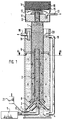
- FIG. 1 shows a foam tube (1) with an inner riser tube (2), the funnel-shaped extension (3) of which delimits an introduction space (4) into which liquid coming from a schematically indicated denitrification (5) is introduced via an inlet (6).
- an air-ozone mixture (originating from the ozonizer indicated schematically by 21) is fed into the liquid inside the funnel (3) in fine bubbles.
- an ozonizer z. B a device from Sander, Elze (FRG) for aqueous applications. The 0 3 fraction is controlled so that no denaturation of existing protein occurs.
- the bubble-free liquid leaving the funnel-shaped end flows upwards in the casing tube (9) and returns via the return tube (10) into the introduction space (4).
- This feedback serves to saturate the liquid with oxygen as effectively as possible, whereby the redox potential can be increased from - 220 to + 200 to + 230 mV.
- this recirculation takes place approx. 60-100 times / h.
- Nitrite contained in the feed water is then oxidized to nitrate.
- this feedback also counteracts the biomass slip of the flotation.
- part of the protein-containing substances present in the water to be treated is still ent in the process hold (slip).
- fillers with filter and adsorber effect or also with microorganisms (e.g. aerobic bacteria) support bodies can be provided, which can develop an additional cleaning effect.
- microorganisms e.g. aerobic bacteria
- the length of the upper end of the foam tube (1) can be extended telescopically to adapt it to the collecting beaker (11) in which the biomass (12) collects, which can be discharged via the outlet (13) with a tube bent downwards.
- the collecting cup (11) On the collecting cup (11) there is a removable sieve attachment (14) with a lower sieve (15) and activated carbon layer (16) through which the air containing ozone is released, as a result of which the ozone is catalytically destroyed.
- a curved plate (17), which prevents biomass from passing into the sieve, is preferably arranged under the sieve (15).
- the biomass contained in the water adheres to the air-ozone bubbles during aeration and rises to the air-water column.
- a more or less solid biomass foam (flotation) forms in the uppermost part of the air-water column.
- This is then pressed into the collecting cup (11) by the escaping air.
- the biomass liquefies there and is discharged via the outlet (13). This protrudes with the drain opening into the flotated biomass and prevents ozone-containing air from escaping above it. This must inevitably pass through the activated carbon layer (16) lying on the collecting cup (11) and is destroyed here.
- the jacket tube had a length of 1010 mm and a diameter of 150 mm.
- the inner riser pipe with a diameter of 40 mm had a length of 820 mm (with funnel 910 mm).
- the 70 mm clear foam tube (1) had a length of 1065 mm to the lower edge of the collecting cup.
- the collecting cup (11) with removable sieve attachment (14) had a height of 120 mm and a diameter of 100 mm. 20 l / h of liquid were introduced via the feed (6).
- Return pipe (10) and liquid outlet (18) had a clear width of 32 mm.
- the arrangement described was used for the aftertreatment of denitrated water for a marine aquarium. Of course, much larger versions (e.g. for 1000 I / h) or smaller versions can be implemented as required.
- the device can also be used to separate protein-containing substances in aerobic water treatment or to clarify waste water from the fish or meat processing industry.
Landscapes
- Life Sciences & Earth Sciences (AREA)
- Engineering & Computer Science (AREA)
- Biotechnology (AREA)
- Water Supply & Treatment (AREA)
- Organic Chemistry (AREA)
- Biodiversity & Conservation Biology (AREA)
- Environmental Sciences (AREA)
- Chemical & Material Sciences (AREA)
- Hydrology & Water Resources (AREA)
- Environmental & Geological Engineering (AREA)
- Marine Sciences & Fisheries (AREA)
- Microbiology (AREA)
- Animal Husbandry (AREA)
- Physical Water Treatments (AREA)
- Treatment Of Water By Oxidation Or Reduction (AREA)
- Apparatus Associated With Microorganisms And Enzymes (AREA)
- Aeration Devices For Treatment Of Activated Polluted Sludge (AREA)
- Physical Or Chemical Processes And Apparatus (AREA)
- Biological Treatment Of Waste Water (AREA)
- Saccharide Compounds (AREA)
Description
- Die Erfindung bezieht sich auf einen Begasungs/Flotations-Reaktor insbesondere für Biomasse enthaltende Flüssigkeit mit einem Schaumrohr mit oberem Auffangbecher sowie einem unteren Einleitungsraum für Flüssigkeit und Gas in Form feiner Blasen.
- Begasung und Flotation von biomassehaltigen Flüssigkeiten können in unterschiedlichen Bereichen der Biotechnologie eine Rolle spielen. Ein spezielles Beispiel ist die Abwasserbehandlung von Meerwasseraquarien, auf die hier besonders Bezug genommen wird.
- Bei solchen Aquarien wird dem Wasser durch die Fütterung ständig eiweißhaltige Substanz zugeführt, deren Abbau durch Mikroorganismen über längere Zeit hinweg zu einer Anreicherung von speziell für empfindliche Meerestiere schädlichem Nitrat führt.
- Eine Möglichkeit, den Nitratgehalt niedrig zu halten besteht in der denitrifizierenden Behandlung des Wassers in einem rotierenden Festbettreaktor, wie er in der Deutschen Patentanmeldung DE-A 3 608 466 vom 14.03.1986 der Anmelderin beschrieben ist. Das in einem solchen Reaktor denitrifizierte Wasser kann nun jedoch nicht ohne Nachbehandlung wieder in das Aquarium zurückgeleitet werden, da es
- - keinen lebenswichtigen Sauerstoff enthält,
- - mit wassertrübender Biomasse durchsetzt ist,
- - ein Redoxpotential von - 220 mV (Sollwert + 200 bis + 230 mV) aufweist und
- - eventuell Nitrit enthält, das bereits in geringen Konzentrationen (ab 1 mg/I) äußerst giftig ist.
- Der erfindungsgemäße Begasungs/Flotations-Reaktor bezweckt daher eine Nachbehandlung des Wassers, das soweit mit Sauerstoff beladen und von Biomasse sowie Nitrit befreit wird, daß es erneut in das Aquarium eingeleitet werden kann.
- Zu diesem Zweck ist der erfindungsgemäße Begasungs/Flotations-Reaktor der Eingangs genannten Art dadurch gekennzeichnet, daß das Schaumrohr ein den Einleitungsraum abschließendes axiales Steigrohr aufweist, über welches das konzentrische Schaumrohr übergreift bzw. übergestülpt ist, dessen unteres trichterförmig erweitertes Ende in den unteren Bereich eines Mantelrohres einmündet, dessen oberes Ende über zumindest ein Rückführungsrohr mit dem Einleitungsraum unter dem axialen Steigrohr in Verbindung steht und das einen T-förmigen Flüssigkeitsauslaß aufweist mit einem Tauchstutzen, der unter den Flüssigkeitsspiegel reicht unter einer Auslaßhöhe unmittelbar über dem Abzweig des Rückführungsrohres, wobei das obere Ende des Schaumrohres teleskopartig verlängerbar ist.
- Zwar ist ein Schaumrohr mit Absetzbecher und unterem Einleitungsraum bereits aus "Zeitschrift des Kölner Zoo" 22 (1979) 69 - 72 bekannt, jedoch ist diese Anordnung in ihrer Wirkungsweise nicht effektiv genug, als daß die vorstehende Forderung erfüllt werden könnte.
- Besondere Ausgestaltungen der Erfindung gehen aus den Unteransprüchen hervor.
- Nachfolgend wird die Erfindung anhand eines Ausführungsbeispiels unter Bezugnahme auf die angefügten Zeichnungen beschrieben: es zeigen:
- Figur 1 einen Begasungs/Flotations-Reaktor im Längsschnitt und
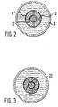
- Figuren 2 und 3 zwei Querschnitte längs A-A durch einen mit Leitrippen versehenen Reaktor
- Figur 1 zeigt ein Schaumrohr (1) mit einem inneren Steigrohr (2), dessen trichterförmige Verlängerung (3) einen Einleitungsraum (4) abgrenzt, in den von einer schematisch angedeuteten Denitrifikation (5) herkommende Flüssigkeit über einen Zulauf (6) eingeleitet wird. Über einen oder mehrere Gasverteiler (7), die insbesondere durch Lindenholzausströmer gebildet werden, wird ein Luft-Ozongemisch (herkommend vom schematisch mit 21 angedeuteten Ozonisator) feinstblasig in die Flüssigkeit innerhalb des Trichters (3) zugeführt. Als Ozonisator dient z. B. ein Gerät der Fa. Sander, Elze (BRD) für wäßrigen Bereich. Der 03-Anteil wird so gesteuert, daß noch keine Denaturierung von vorhandenem Eiweiß auftritt.
- Im Steigrohr (2) steigen Gas und Flüssigkeit nach dem Luftheberprinzip aufwärts und gelangen in das Schaumrohr, in dem sich nach oben zu eine Schaumsäule aufbaut, während gleichzeitig eine Abwärtsströmung in dem das Steigrohr umgebenden Abschnitt stattfindet, mit der die Gasblasen abwärtswandern bis zu dem als "Sogentspannungskonus" bezeichneten trichterförmigen Ende (8) in dem die Strömung soweit verlangsamt wird, daß eine Blasenumkehr stattfindet. Das nunmehr wieder aufwärtsströmende Gas begegnet den abwärtsbewegten Blasen, was zu einer kräftigen Durchwirbelung Anlaß gibt, wodurch die Verweilzeit des Gases in der Flüssigkeit erhöht und die Auflösung des Gases im Wasser begünstigt wird. D. h. zwischen Steigrohr und Schaumrohr findet eine turbulente Bewegung der Blasen in beiden Richtungen (sowohl aufwärts als auch abwärts) statt.
- Zwischen Steigrohr und Schaumrohr können als Leitrippen 22, wie durch Figuren 2 und 3 angedeutet wird, gegebenenfalls gewundene Längsrippen vorgesehen sein, die zu einer Verlängerung der Strömungswege führen.
- Die das trichterförmige Ende verlassende blasenfreie Flüssigkeit strömt im Mantelrohr (9) aufwärts und gelangt über das Rückführungsrohr (10) wieder in den Einleitungsraum (4) zurück. Diese Rückführung dient der möglichst effektiven Aufsättigung der Flüssigkeit mit Sauerstoff, wodurch eine Anhebung des Redoxpotentials von - 220 auf + 200 bis + 230 mV erreicht werden kann. Diese Rückführung erfolgt je nach Luftzufuhr und Zufuhr von aufzubereitendem Wasser ca. 60 - 100 mal/h. Im Zulaufwasser enthaltenes Nitrit ist dann zu Nitrat aufoxidiert. Gleichzeitig wird durch diese Rückführung auch dem Biomassenschlupf der Flotation entgegengewirkt. Bei bekannten Vorrichtungen ist dagegen ein Teil der im zu behandelnden Wasser vorhandenen eiweißhaltigen Substanzen noch im Ablauf enthalten (Schlupf).
- Im Raum zwischen Mantelrohr (9) und Schaumrohr (1) können Füllkörper mit Filter- und Adsorberwirkung oder auch mit Mikroorganismen (z. B. aeroben Bakterien) bewachsene Trägerkörper vorgesehen sein, die eine zusätzliche Reinigungswirkung entfalten können.
- Das obere Ende des Schaumrohrs (1) ist in seiner Länge teleskopartig verlängerbar zur Anpassung an den Auffangbecher (11), in dem sich die Biomasse (12) sammelt, die über den Ablauf (13) mit einem nach unten abgebogenen Rohr abgegeben werden kann. Auf dem Auffangbecher (11) befindet sich ein abnehmbarer Siebaufsatz (14) mit unterem Sieb (15) und Aktivkohleschicht (16) über die die ozonhaltige Luft abgegeben wird, wodurch das Ozon katalytisch zerstört wird.
- Unter dem Sieb (15) ist vorzugsweise eine gewölbte Platte (17) angeordnet, die einen Übertritt von Biomasse in das Sieb hinein verhindert.
- Belüftete und von Biomasse befreite Flüssigkeit verläßt das Mantelrohr (9) über den Flüssigkeitsauslaß (18), dessen unterer Tauchstutzen (19) unter die Flüssigkeitsoberfläche reicht, wodurch ein Mitreißen von Gas und aufschwimmender Biomasse verhindert wird.
- Je nach Luftdosierung baut sich über dem Flüssigkeitsspiegel (20) eine Luft-Wassersäule innerhalb des Schaumrohres (1) auf. Die Höhe dieser Säule ist abhängig von
- - der zugeführten Luftmenge,
- - Querschnitt und der Länge des inneren Steigrohres (2),
- - Querschnitt und der Länge des Schaumrohres (1 ),
- - der Oberflächenspannung des zu behandelnden Wassers,
- - der Belastung mit Biomasse,
- - der Ozonzufuhr,
- - dem Luftblasenquerschnitt.
- Da beim Betrieb ständig Wasser nachgefördert wird, und dieses das Schaumrohr (1) nicht nach oben hin verlassen kann, entsteht an der Oberkante des inneren Steigrohres (2) ein Druck, der ausreicht, einen Teilstrom des geförderten Wassers durch das Schaumrohr (1) nach unten zu leiten. Dieser Druck ist abhängig von der geförderten Wassermenge und der im Schaumrohr aufstehenden Luft-Wassersäule. Gleichzeitig werden die im Wasser befindlichen Luft-Ozon-Blasen mit dem nach unten fließenden Wasser bis zum trichterförmigen Ende (8) gesogen, und steigen von dort wieder auf.
- Die im Wasser enthaltene Biomasse lagert sich während der Belüftung an die Luft-Ozon-Blasen an und steigt bis in die Luft-Wassersäule. Je nach Einstellung der vorstehend genannten Parameter bildet sich ein mehr oder weniger fester Biomasseschaum (Flotation) im obersten Teil der Luft-Wassersäule. Dieser wird dann von der entweichenden Luft in den Auffangbecher (11) gedrückt. Dort verflüssigt sich die Biomasse und wird über den Ablauf (13) abgeleitet. Dieser ragt mit der Ablauföffnung in die abflotierte Biomasse und verhindert, daß ozonhaltige Luft über ihm entweichen kann. Dies muß zwangsläufig über die dem Auffangbecher (11) liegende Aktivkohleschicht (16) passieren und wird hier zerstört.
- Die vorstehend beschriebene Anordnung zeichnet sich durch eine hohe Effektivität hinsichtlich der Aufsättigung der behandelten Flüssigkeit mit Gas (Sauerstoff) und eine gute Abtrennung von Biomasse bei geringen Betriebskosten und geringer Größe des Gerätes aus. Bei einem Laborgerät hatte das Mantelrohr eine Länge von 1010 mm und einen Durchmesser von 150 mm. Das innere Steigrohr von 40 mm Durchmesser hatte eine Länge von 820 mm (mit Trichter 910 mm). Das 70 mm lichte Schaumrohr (1) hatte eine Länge von 1065 mm bis zur Unterkante des Auffangbechers. Der Auffangbecher (11) mit abnehmbarem Siebaufsatz (14) hatte eine Höhe von 120 mm und einen Durchmesser von 100 mm. Über den Zulauf (6) wurden 20 I/h Flüssigkeit eingeleitet.
- Rückführungsrohr (10) und Flüssigkeitsauslaß (18) hatten eine lichte Weite von 32 mm. Die beschriebene Anordnung diente zur Nachbehandlung von denitriertem Wasser für ein Meerwasseraquarium. Selbstverständlich sind weit größere Ausführungen (z. B. für 1000 I/h) oder auch kleinere Varianten je nach Bedarf ausführbar.
- Das Gerät kann auch zur Abtrennung von eiweißhaltigen Substanzen bei der aeroben Wasseraufbereitung benutzt werden oder zur Klärung von Abwasser der Fisch oder Fleisch verarbeitenden Industrie.
Claims (6)
Priority Applications (1)
| Application Number | Priority Date | Filing Date | Title |
|---|---|---|---|
| AT87118371T ATE52072T1 (de) | 1986-12-22 | 1987-12-11 | Begasungs/flotationsreaktor. |
Applications Claiming Priority (2)
| Application Number | Priority Date | Filing Date | Title |
|---|---|---|---|
| DE3643931 | 1986-12-22 | ||
| DE19863643931 DE3643931A1 (de) | 1986-12-22 | 1986-12-22 | Begasungs/flotationsreaktor |
Publications (2)
| Publication Number | Publication Date |
|---|---|
| EP0274083A1 EP0274083A1 (de) | 1988-07-13 |
| EP0274083B1 true EP0274083B1 (de) | 1990-04-18 |
Family
ID=6316897
Family Applications (1)
| Application Number | Title | Priority Date | Filing Date |
|---|---|---|---|
| EP87118371A Expired - Lifetime EP0274083B1 (de) | 1986-12-22 | 1987-12-11 | Begasungs/Flotationsreaktor |
Country Status (8)
| Country | Link |
|---|---|
| US (1) | US4834872A (de) |
| EP (1) | EP0274083B1 (de) |
| JP (1) | JPH0811235B2 (de) |
| AT (1) | ATE52072T1 (de) |
| AU (1) | AU8281887A (de) |
| DE (2) | DE3643931A1 (de) |
| DK (1) | DK165240C (de) |
| FI (1) | FI90857C (de) |
Cited By (1)
| Publication number | Priority date | Publication date | Assignee | Title |
|---|---|---|---|---|
| DE4432042A1 (de) * | 1994-09-09 | 1996-03-14 | Forschungszentrum Juelich Gmbh | Begasungs-/Flotations-Reaktor und Regeleinrichtung |
Families Citing this family (76)
| Publication number | Priority date | Publication date | Assignee | Title |
|---|---|---|---|---|
| US5080780A (en) * | 1988-10-11 | 1992-01-14 | Process Development Company | Single cell vertical static flow flotation unit cross-reference to related applications |
| US5011597A (en) * | 1988-10-11 | 1991-04-30 | Canzoneri Anthony S | Single cell vertical static flow flotation unit |
| NO885455L (no) * | 1988-12-08 | 1990-06-11 | Sunfish Ltd As | Fremgangsmaate og anordning for rensing av vann. |
| US5006230A (en) * | 1989-04-03 | 1991-04-09 | Votava Iii Paul | Dual-action aquarium filter |
| US5053140A (en) * | 1989-07-26 | 1991-10-01 | American Water Purification, Inc. | Process and apparatus for removing impurities from water used in food processing utilizing a mixture of ozone and air |
| US5021153A (en) * | 1989-11-20 | 1991-06-04 | G-H Systems, Inc. | Combined apparatus for removing grit and grease from sewage |
| US5080802A (en) * | 1990-05-09 | 1992-01-14 | Cairo Jr John A | Induced gas liquid coalescer and flotation separator |
| US5156745A (en) * | 1990-05-09 | 1992-10-20 | Cairo Jr John A | Induced gas liquid coalescer and flotation separator |
| US5078867A (en) * | 1990-05-18 | 1992-01-07 | Michael Danner | Aquarium filter/protein skimmer system |
| US5762781A (en) * | 1990-11-23 | 1998-06-09 | Atomaer Pty. Ltd. | Flotation apparatus and process |
| DE4214318C1 (de) * | 1992-05-04 | 1993-10-28 | Neuhaus Adolf Ing Grad | Vorrichtung zum Abschäumen von im wesentlichen organischen, im Süßwasser oder Seewasser enthaltenen Bestandteilen |
| US5326469A (en) * | 1992-09-14 | 1994-07-05 | Zander Filter Systems, Inc. | Method and apparatus for separating oil and water |
| WO1994027918A1 (en) * | 1993-05-25 | 1994-12-08 | Nauchno-Proizvodstvennaya Firma Bifar | Waste water treatment method, suspensed matter separation method, and method for saturating a liquid with a gas |
| US7384555B1 (en) | 1993-09-22 | 2008-06-10 | Kurita Water Industries Ltd. | Process for biological treatment of aqueous organic wastes |
| JP3351047B2 (ja) * | 1993-09-27 | 2002-11-25 | 栗田工業株式会社 | 生物汚泥の処理方法 |
| NO180744C (no) * | 1994-02-07 | 1997-06-11 | Puraq As | Fremgangsmåte og anordning for rensing av vann |
| ES2079316B1 (es) * | 1994-02-23 | 1996-08-16 | Univ Oviedo | Sistema integrado flotacion-biologico de tratamiento de aguas residuales. |
| DE4416447C1 (de) * | 1994-05-10 | 1995-08-24 | Aqua Medic Anlagenbau Gmbh | Eiweißabschäumer |
| US5484525A (en) * | 1994-07-13 | 1996-01-16 | Aquarium Systems, Inc. | Foam fractionation protein skimmer assembly |
| US6143187A (en) * | 1994-10-07 | 2000-11-07 | Robertson; Mark B. | Fluidized bed filter for an aquarium |
| WO1996011045A2 (en) * | 1994-10-07 | 1996-04-18 | Mark Robertson | Fluidized bed filter |
| EP0794926B1 (de) * | 1994-11-18 | 2000-03-15 | BCDE Group Waste Management Ltd Oy | Vorrichtung zum trennen von flock |
| US6086732A (en) * | 1994-11-18 | 2000-07-11 | Bcde Group Waste Management Ltd Oy | Flock separating apparatus |
| US5527455A (en) * | 1995-01-23 | 1996-06-18 | Hoffa; Gary | Fluidized bed biological filter system for fish tanks |
| US5672268A (en) * | 1995-04-03 | 1997-09-30 | Red Sea Fish Pharm Ltd. | Fluid treatment apparatus |
| US5554280A (en) * | 1995-05-15 | 1996-09-10 | Loehr; Gary | Filter system |
| US6090294A (en) * | 1995-06-23 | 2000-07-18 | Ajt & Associates, Inc. | Apparatus for the purification of water and method therefor |
| US5785864A (en) * | 1995-06-23 | 1998-07-28 | Ajt & Associates, Inc. | Apparatus for the purification of water and method therefor |
| JPH0919694A (ja) * | 1995-07-05 | 1997-01-21 | Mitsubishi Electric Corp | オゾン浄化装置 |
| US5562821A (en) * | 1995-07-21 | 1996-10-08 | Commonwealth Of Puerto Rico | Foam fractionator |
| KR100188878B1 (ko) * | 1995-10-27 | 1999-06-01 | 김해수 | 폐타이어를 이용한 오폐수처리용 과립담체와 그 제조방법 및 이 과립담체를 이용한 오폐수 처리장치 |
| US5665227A (en) * | 1995-11-29 | 1997-09-09 | Watt; Ronald | Dual-flow protein skimmer |
| US6001247A (en) * | 1996-05-01 | 1999-12-14 | Schulz; Christopher R. | Removable, in-line diffuser apparatus for ozone disinfection of water |
| US5736034A (en) * | 1996-08-27 | 1998-04-07 | James W. Phillips | Protein removal system |
| JP2972992B2 (ja) * | 1996-10-24 | 1999-11-08 | 芳一 岡田 | 有機質廃液の曝気槽とその曝気槽を用いた曝気処理装置 |
| FR2762232B1 (fr) * | 1997-04-17 | 1999-05-28 | Degremont | Procede et dispositif pour la mise en contact de l'ozone dans des fluides a traiter, notamment de l'eau |
| DE19719798C1 (de) * | 1997-05-10 | 1999-02-11 | Forschungszentrum Juelich Gmbh | Verfahren zum Entfernen von Biomasse aus einer Flüssigkeit mit Hilfe eines Flotationsreaktors |
| US5866018A (en) * | 1997-09-18 | 1999-02-02 | The Hartz Mountain Corporation | Vortex aquarium filter |
| DE19756962A1 (de) * | 1997-12-20 | 1999-07-01 | Forschungszentrum Juelich Gmbh | Flotationsreaktor sowie Verfahren zur Flotation |
| USD424660S (en) * | 1998-07-27 | 2000-05-09 | Ajt & Associates, Inc. | Apparatus for the purification of water |
| USD420720S (en) * | 1998-07-27 | 2000-02-15 | AJT & Associates | Apparatus for the purification of water |
| US6436295B2 (en) * | 1999-02-11 | 2002-08-20 | Jason Kim | Protein skimmer |
| US6156209A (en) * | 1999-02-11 | 2000-12-05 | Kim; Jason | Protein skimmer |
| DE19909172C2 (de) | 1999-03-03 | 2003-06-12 | Erwin Sander Elektroappbau Gmb | Verfahren zum Fördern und Reinigen von Salzwasser in einer Fischaufzuchtanlage und Flotationsturm zur Verwendung in dem Verfahren |
| FR2807026B1 (fr) * | 2000-04-03 | 2003-01-31 | Ifremer | Dispositif et procede de traitement d'eau par ecumage |
| DE10017822A1 (de) * | 2000-04-10 | 2001-10-18 | Spengler Erika | Vorrichtung zum Abscheiden von Fremdpartikeln |
| IL135787A0 (en) * | 2000-04-23 | 2001-05-20 | Red Sea Fish Pharm Ltd | Protein skimmer |
| US6524486B2 (en) * | 2000-12-27 | 2003-02-25 | Sepal Technologies Ltd. | Microalgae separator apparatus and method |
| KR20010074118A (ko) * | 2001-03-27 | 2001-08-04 | 조석찬 | 본 발명의 기술분야는 활어수 정화장치이다. |
| KR100432479B1 (ko) * | 2001-06-11 | 2004-05-22 | 주식회사 레비텍 | 어류의 오염물질 정화장치 |
| US20030201232A1 (en) * | 2002-04-29 | 2003-10-30 | Matthew Cheyne | Flotation/fractionation systems for treating liquids and in separation of liquids to be treated thereby |
| GB2404159A (en) * | 2003-07-24 | 2005-01-26 | John Andrew Timmins | A separating device |
| ITRE20030093A1 (it) * | 2003-09-30 | 2005-04-01 | Acqua & Co S R L | Dispositivo perfezionato per l'abbattimento di schiume. |
| EA200800735A1 (ru) * | 2005-09-02 | 2008-08-29 | Кумминскорп Лимитед | Установка для обработки воды |
| KR100714237B1 (ko) | 2005-09-21 | 2007-05-04 | 주식회사 네가트론 | 엘씨알 순환 여과 유니트 |
| WO2008126091A2 (en) * | 2007-04-17 | 2008-10-23 | Red Sea Fish Pharm Ltd | Protein skimmer |
| DE102008044888B4 (de) * | 2008-08-29 | 2015-05-07 | Iwat Industrie-Wasser-Aufbereitungs-Technik Gmbh | Flotationsanlage |
| US8569050B1 (en) | 2009-05-04 | 2013-10-29 | John D. Ericsson | Enclosed bioreactor system and methods associated therewith |
| FR2952370B1 (fr) * | 2009-11-09 | 2012-12-14 | Inst Nat Sciences Appliq | Procede de recuperation de microparticules inertes ou vivantes et son installation |
| US9868649B2 (en) * | 2010-06-25 | 2018-01-16 | Nexus Ewater Pty Ltd. | Process and apparatus for purifying water |
| US20140070429A1 (en) * | 2012-09-10 | 2014-03-13 | Jyh-Ying Lee | Dirt disposal structure of aquarium protein skimmer |
| US9193616B2 (en) * | 2012-10-18 | 2015-11-24 | Bader Shafaqa Al-Anzi | Mobile buoyant aerator |
| CN103523894A (zh) * | 2013-10-28 | 2014-01-22 | 哈尔滨工业大学 | 一种高锰酸盐均相催化氧化水处理的方法 |
| AU2015311611B2 (en) * | 2014-09-02 | 2020-08-27 | Fluence Corporation Limited | Apparatus for treating water |
| CN104694379A (zh) * | 2015-01-22 | 2015-06-10 | 张玲玲 | 多区域环形超高效沼气发酵系统提升菌种均匀分布的装置 |
| CN104694376A (zh) * | 2015-01-22 | 2015-06-10 | 张玲玲 | 多区域沼液紊流带动菌种均匀分布的超高效发酵系统 |
| CN104498334B (zh) * | 2015-01-22 | 2016-06-29 | 陆永柱 | 水压式沼液弯曲流动搅拌的超高效甲烷发生系统 |
| CN104480001B (zh) * | 2015-01-22 | 2016-06-29 | 葛余惟 | 水压式紊流搅拌布菌的超高效甲烷发生系统 |
| CN104560660B (zh) * | 2015-01-22 | 2016-09-07 | 温州市兴泰科技有限公司 | 直筒型水压式甲烷发酵装置 |
| CN104560666B (zh) * | 2015-01-22 | 2016-09-07 | 青岛橡胶谷知识产权有限公司 | 多区域混合流动布菌的双筒捆绑式甲烷发生系统 |
| CN104673634A (zh) * | 2015-01-22 | 2015-06-03 | 张玲玲 | 沼液紊流搅拌型超高效沼气发酵系统 |
| CN104804992A (zh) * | 2015-05-27 | 2015-07-29 | 张伟伟 | 超长路径的发酵系统 |
| SE541852C2 (en) * | 2017-09-04 | 2019-12-27 | Wallenius Water Innovation Ab | A system for providing a flow to a fluid, a tank comprising the system and a method |
| CN111719329A (zh) * | 2020-06-29 | 2020-09-29 | 晋海利 | 一种基于微气泡浮选的废纸回收用多段式脱墨装置 |
| US11635054B1 (en) * | 2022-08-04 | 2023-04-25 | Wilfred S. Streeter | Vertical water pumping system |
| WO2024134647A1 (en) | 2022-12-18 | 2024-06-27 | Red Sea Aquatics Development Ltd | Self-regulating protein skimmer and retrofit kits for retrofitting non self-regulating protein skimmers |
Family Cites Families (4)
| Publication number | Priority date | Publication date | Assignee | Title |
|---|---|---|---|---|
| US3505188A (en) * | 1965-06-18 | 1970-04-07 | Fairbanks Morse Inc | Electrolytic flotation method and apparatus |
| EP0086019B2 (de) * | 1982-02-09 | 1989-11-29 | BBC Brown Boveri AG | Vorrichtung zur Begasung einer Flüssigkeit und Verfahren zum Betrieb der Vorrichtung |
| FR2545732B1 (fr) * | 1983-05-10 | 1989-10-27 | Lyonnaise Eaux Eclairage | Appareil pour la dissolution d'ozone dans un fluide |
| US4749493A (en) * | 1986-10-07 | 1988-06-07 | Hicks Charles E | Method and apparatus for oxygenating water |
-
1986
- 1986-12-22 DE DE19863643931 patent/DE3643931A1/de not_active Withdrawn
-
1987
- 1987-12-11 AT AT87118371T patent/ATE52072T1/de not_active IP Right Cessation
- 1987-12-11 EP EP87118371A patent/EP0274083B1/de not_active Expired - Lifetime
- 1987-12-11 DE DE8787118371T patent/DE3762333D1/de not_active Expired - Lifetime
- 1987-12-17 US US07/134,230 patent/US4834872A/en not_active Expired - Lifetime
- 1987-12-18 AU AU82818/87A patent/AU8281887A/en not_active Abandoned
- 1987-12-21 JP JP62321618A patent/JPH0811235B2/ja not_active Expired - Lifetime
- 1987-12-21 FI FI875644A patent/FI90857C/fi not_active IP Right Cessation
- 1987-12-21 DK DK673987A patent/DK165240C/da not_active IP Right Cessation
Cited By (2)
| Publication number | Priority date | Publication date | Assignee | Title |
|---|---|---|---|---|
| DE4432042A1 (de) * | 1994-09-09 | 1996-03-14 | Forschungszentrum Juelich Gmbh | Begasungs-/Flotations-Reaktor und Regeleinrichtung |
| DE4432042C2 (de) * | 1994-09-09 | 1998-07-02 | Forschungszentrum Juelich Gmbh | Begasungs-/Flotations-Reaktor mit Anordnungen zur Abtrennung von Feststoffen aus Flüssigkeiten |
Also Published As
| Publication number | Publication date |
|---|---|
| DK165240B (da) | 1992-10-26 |
| DE3643931A1 (de) | 1988-07-07 |
| DE3762333D1 (de) | 1990-05-23 |
| FI875644A0 (fi) | 1987-12-21 |
| AU8281887A (en) | 1988-06-23 |
| JPH0811235B2 (ja) | 1996-02-07 |
| DK165240C (da) | 1993-03-22 |
| DK673987D0 (da) | 1987-12-21 |
| FI90857B (fi) | 1993-12-31 |
| US4834872A (en) | 1989-05-30 |
| FI875644A7 (fi) | 1988-06-23 |
| DK673987A (da) | 1988-06-23 |
| ATE52072T1 (de) | 1990-05-15 |
| EP0274083A1 (de) | 1988-07-13 |
| JPS63166498A (ja) | 1988-07-09 |
| FI90857C (fi) | 1994-04-11 |
Similar Documents
| Publication | Publication Date | Title |
|---|---|---|
| EP0274083B1 (de) | Begasungs/Flotationsreaktor | |
| DE3887711T2 (de) | Vorrichtung und Verfahren zur Behandlung von unter hohem Druck mit Sauerstoff gesättigtem Wasser. | |
| DE2216304C3 (de) | Einrichtung zur Umwälzung und Belüftung einer sich in einem Belebungsbecken einer Kläranlage befindenden Flüssigkeit | |
| EP0306053B1 (de) | Reaktor und Verfahren zum biologischen Reinigen von schadstoffhaltigem Wasser | |
| EP0086019B1 (de) | Vorrichtung zur Begasung einer Flüssigkeit und Verfahren zum Betrieb der Vorrichtung | |
| DE2523591C3 (de) | Vorrichtung zur Belüftung von verunreinigtem Wasser mittels einer Wasserstrahlpumpe | |
| EP0163159B1 (de) | Verfahren zur biologischen Reinigung von Abwasser | |
| DE2407008B2 (de) | Verfahren zur biologischen Entfernung von organischem Kohlenstoff aus Abwasser | |
| DD253247A5 (de) | Verfahren zur biologischen abwasserreinigung | |
| DE2708653C3 (de) | Anlage zur Behandlung von pumpfähigem Abfallstoff | |
| DE2901509C2 (de) | Vorrichtung zur biologischen Behandlung von Abwasser | |
| DE4201167A1 (de) | Verfahren zur biologischen aeroben oder anaeroben behandlung von abwasser | |
| DE2518570B2 (de) | Verfahren zur biologischen reinigung von abwasser | |
| DE2625608C2 (de) | Umlaufbecken zum Umwälzen und Belüften von Abwasser | |
| DE3031755C2 (de) | Verfahren und Vorrichtung zur kontinuierlichen chemischen Behandlung von gelöste, emulgierte und/oder kolloidale Stoffe enthaltenden Flüssigkeiten und zur Abtrennung dieser Stoffe mit Hilfe der Schwerkraft | |
| DE4308159A1 (de) | Verfahren zum Abbau der CSB-Belastung in Abwasser | |
| DE2612255A1 (de) | Verfahren und anlage zur reinigung von abwasser nach dem belebtschlammverfahren | |
| EP0154915B1 (de) | Verfahren und Vorrichtung zur biologischen Reinigung von Abwasser | |
| DD233825A1 (de) | Vorrichtung zur grob- und feinreinigung von wasser | |
| DE4013226C1 (de) | ||
| DE10245466B4 (de) | Verfahren zum biologischen Reinigen von Abwasser | |
| DE3838846C2 (de) | ||
| DE2256874A1 (de) | Abwasserbehandlungsvorrichtung | |
| DE2542167C3 (de) | Verfahren zur Flotation von in verunreinigtem Wasser dispergierten und/oder emulgierten Teilchen | |
| DE2515667A1 (de) | Verfahren und vorrichtung zum belueften von biologisch abbaubarem klaerschlamm |
Legal Events
| Date | Code | Title | Description |
|---|---|---|---|
| PUAI | Public reference made under article 153(3) epc to a published international application that has entered the european phase |
Free format text: ORIGINAL CODE: 0009012 |
|
| AK | Designated contracting states |
Kind code of ref document: A1 Designated state(s): AT BE CH DE ES FR GB GR IT LI LU NL SE |
|
| 17P | Request for examination filed |
Effective date: 19880616 |
|
| 17Q | First examination report despatched |
Effective date: 19890426 |
|
| GRAA | (expected) grant |
Free format text: ORIGINAL CODE: 0009210 |
|
| RAP3 | Party data changed (applicant data changed or rights of an application transferred) |
Owner name: FORSCHUNGSZENTRUM JUELICH GMBH |
|
| AK | Designated contracting states |
Kind code of ref document: B1 Designated state(s): AT BE CH DE FR GB LI NL |
|
| REF | Corresponds to: |
Ref document number: 52072 Country of ref document: AT Date of ref document: 19900515 Kind code of ref document: T |
|
| REF | Corresponds to: |
Ref document number: 3762333 Country of ref document: DE Date of ref document: 19900523 |
|
| GBT | Gb: translation of ep patent filed (gb section 77(6)(a)/1977) | ||
| ET | Fr: translation filed | ||
| PLBE | No opposition filed within time limit |
Free format text: ORIGINAL CODE: 0009261 |
|
| STAA | Information on the status of an ep patent application or granted ep patent |
Free format text: STATUS: NO OPPOSITION FILED WITHIN TIME LIMIT |
|
| 26N | No opposition filed | ||
| REG | Reference to a national code |
Ref country code: GB Ref legal event code: IF02 |
|
| PGFP | Annual fee paid to national office [announced via postgrant information from national office to epo] |
Ref country code: DE Payment date: 20061130 Year of fee payment: 20 |
|
| PGFP | Annual fee paid to national office [announced via postgrant information from national office to epo] |
Ref country code: FR Payment date: 20061215 Year of fee payment: 20 |
|
| PGFP | Annual fee paid to national office [announced via postgrant information from national office to epo] |
Ref country code: GB Payment date: 20061218 Year of fee payment: 20 Ref country code: NL Payment date: 20061218 Year of fee payment: 20 |
|
| PGFP | Annual fee paid to national office [announced via postgrant information from national office to epo] |
Ref country code: AT Payment date: 20061222 Year of fee payment: 20 |
|
| PGFP | Annual fee paid to national office [announced via postgrant information from national office to epo] |
Ref country code: CH Payment date: 20061227 Year of fee payment: 20 |
|
| PGFP | Annual fee paid to national office [announced via postgrant information from national office to epo] |
Ref country code: BE Payment date: 20070112 Year of fee payment: 20 |
|
| BE20 | Be: patent expired |
Owner name: *FORSCHUNGSZENTRUM JULICH G.M.B.H. Effective date: 20071211 |
|
| REG | Reference to a national code |
Ref country code: GB Ref legal event code: PE20 |
|
| REG | Reference to a national code |
Ref country code: CH Ref legal event code: PL |
|
| PG25 | Lapsed in a contracting state [announced via postgrant information from national office to epo] |
Ref country code: NL Free format text: LAPSE BECAUSE OF EXPIRATION OF PROTECTION Effective date: 20071211 |
|
| NLV7 | Nl: ceased due to reaching the maximum lifetime of a patent |
Effective date: 20071211 |
|
| PG25 | Lapsed in a contracting state [announced via postgrant information from national office to epo] |
Ref country code: GB Free format text: LAPSE BECAUSE OF EXPIRATION OF PROTECTION Effective date: 20071210 |