EP0274214A1 - Méthode de commande de vitesse de rotation d'un disque d'enregistrement d'informations - Google Patents
Méthode de commande de vitesse de rotation d'un disque d'enregistrement d'informations Download PDFInfo
- Publication number
- EP0274214A1 EP0274214A1 EP87310515A EP87310515A EP0274214A1 EP 0274214 A1 EP0274214 A1 EP 0274214A1 EP 87310515 A EP87310515 A EP 87310515A EP 87310515 A EP87310515 A EP 87310515A EP 0274214 A1 EP0274214 A1 EP 0274214A1
- Authority
- EP
- European Patent Office
- Prior art keywords
- marks
- information recording
- recording disk
- rotational velocity
- patterns
- Prior art date
- Legal status (The legal status is an assumption and is not a legal conclusion. Google has not performed a legal analysis and makes no representation as to the accuracy of the status listed.)
- Granted
Links
- 238000000034 method Methods 0.000 title claims abstract description 25
- 230000001276 controlling effect Effects 0.000 description 4
- 238000010586 diagram Methods 0.000 description 4
- 230000000875 corresponding effect Effects 0.000 description 3
- 230000003287 optical effect Effects 0.000 description 3
- 230000003247 decreasing effect Effects 0.000 description 2
- 125000004122 cyclic group Chemical group 0.000 description 1
- 238000004519 manufacturing process Methods 0.000 description 1
- 238000012986 modification Methods 0.000 description 1
- 230000004048 modification Effects 0.000 description 1
Images

Classifications
-
- G—PHYSICS
- G11—INFORMATION STORAGE
- G11B—INFORMATION STORAGE BASED ON RELATIVE MOVEMENT BETWEEN RECORD CARRIER AND TRANSDUCER
- G11B19/00—Driving, starting, stopping record carriers not specifically of filamentary or web form, or of supports therefor; Control thereof; Control of operating function ; Driving both disc and head
- G11B19/20—Driving; Starting; Stopping; Control thereof
- G11B19/24—Arrangements for providing constant relative speed between record carrier and head
- G11B19/247—Arrangements for providing constant relative speed between record carrier and head using electrical means
Definitions
- This invention relates to a method of controlling the rotational velocity of an information recording disk, more particularly, it relates to a method of controlling an information recording disk having one or more tracks which are concentric or spiral and in which information is recorded and/or reproduced, for example, by a laser beam.
- This invention also relates to an information recording disk such as an optical or optical magnetic disk which is useful in performing the method.
- bit length the length of a pattern corresponding to one bit (hereinafter referred to as "bit length" which is formed on the outer periphery of the disk must be longer than the bit length which is formed on the inner periphery, resulting in a low recording density on the outer periphery despite a high recording density on the inner periphery to cause a problem of a reduced recording density of the disk as a whole.
- the disk In order to read the address information accurately, the disk should be rotated at a velocity which corresponds to the position of the pickup. In other words, the address part having the address information to be read out should move relatively to the pickup at a fixed linear velocity. For this purpose, the following conditions are required:
- the invention provides a method of controlling the rotational velocity of an information recording disk as claimed in each of claims 1 to 5 and provides an information recording disk as claimed in each of claims 6 to 10.
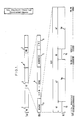
- Figure 1 shows the record format of a track of a preferred example of the information recording disk according to the invention.
- a track 1 has a plurality of ID (address) portions 2 (Fig. 1(a)).
- the ID portions 2 are preferably separated from each other along the track 1 with a fixed distance. As shown in Fig.
- each ID portion 2 comprises a mark 3 indicating the head of the ID portion 2, a VFO-SYNC (variable-frequency oscillator-synchronising) area 4 for operating a PLL (phase-lock loop) circuit to obtain synchronising pulses, an address area 5 showing the address data of the ID portion 2, and a CRC (Cyclic Redundancy Check) area 6 for detecting a bit error in the readout address data.
- the ID portions 2 are pre-formed into a concave-convex shape when manufacturing the disk. (By "concave” is meant a groove or pit in the surface. Conversely, “convex” means a projection, or no groove or pit.) Accordingly, it is possible that data are recorded in, reproduced from or erased from the ID portions 2, but impossible to erase the ID portions 2 themselves.
- the mark pattern consists of a sequence of a first convex portion 7a having a length of 1T (T shows a bit length), a first concave portion 7b having a length of 4T, a second convex portion 7c having a length of 1T, and a second concave portion 7d having a length of 4T.
- the mark pattern is not restricted to the above-mentioned one, but can be formed into any suitable pattern arrangement. However, it is preferable to select the mark pattern so as not to be a pattern which may appear in the data pattern to be recorded.
- the interval during which each pattern passes is measured in terms of a number of clock pulses by a technique well-known in the field. More specifically, the number of clock pulses is counted during the time required for each of the patterns 7a to 7d to pass the pickup of a recording/reproducing apparatus.
- the word "interval" means a time interval between the time when the front edge of a pattern passes the pickup and the time when the rear edge of the pattern passes the pickup.
- the frequency of the clock has a frequency which is 64 times of the bit rate. Namely, when the mark 3 moves at a predetermined linear velocity V L , the interval of the pattern 7a or 7c corresponds to 64 clock pulses.
- the pickup When information is to be recorded onto one of the tracks 1 of a disk rotating at an arbitrary velocity, the pickup is moved by a known technique to a track positioned near the objective track. Then, the interval of each pattern in the track is measured in terms of a number of clock pulses.
- the measured intervals are 64 pulses for the patterns (1T-patterns) 7a and 7c, and 256 pulses for the patterns (4T-patterns) 7b and 7d.
- the measured intervals are 32 pulses for the 1T-patterns, and 128 pulses for the 4T-patterns.
- the measured intervals are 128 pulses for the 1T-patterns, and 512 pulses for the 4T-patterns. Accordingly, when the ratio of the measured interval T n of a first pattern and the measured interval T n+1 of a second pattern which is successive to the first pattern, (i.e., T n+1 /T n ) equals 4, it can be decided that the two patterns belong to any one of the marks 3, irrespective of the linear velocity of the mark or the rotational velocity of the disk. If the ratio of the intervals of two successive patterns is not 4, the intervals of the following two successive patterns are measured at their ratio is calculated until the resulting ratio of intervals of 4 is obtained.
- the embodiment has a series of the 1T-pattern 7a, 4T-pattern 7b, 1T-pattern 7c and 4T-pattern 7d in the mark 3, and, therefore, the ratio of the measured interval (T n+2 ) of a third pattern which is successive to the second pattern and the measured interval (T n+3 ) of a fourth pattern (i.e., T n+3 /T n+2 ) is also calculated, and it can be decided that the patterns belong to any one of the marks 3 when the resulting ratio of 4 is obtained twice consecutively.
- the measured interval (T n+3 ) of the fourth pattern (4T-pattern) 7d is divided by 256 which equals to the interval of the fourth pattern 7d measured when the fourth pattern 7d moves at the predetermined linear velocity V L .
- the ratio T n+3 /256 is calculated.
- the linear velocity of the measured mark 3 can be obtained by multiplying the value obtained from the above calculation by the predetermined linear velocity V L .
- the disk driving device (not shown) is controlled so that the linear velocity of the mark 3 becomes the predetermined linear velocity V L .
- the rotational velocity of the disk is increased when the ratio T n+3 /256 is smaller than 1, and the rotational velocity is decreased when the ratio T n+3 /256 is greater than 1.
- the above processes are repeated until the track 1 or the mark 3 rotates at the predetermined linear velocity V L .
- Figure 2 shows a flow chart of these processes.
- the address data of the address portion 4 are read out to confirm whether or not the mark 3 or ID portion 2 belongs to the objective portion into which the information is to be recorded.
- the readout data are objective ones, the information to be recorded is recorded, and when the data are not objective ones, the pickup is moved onto another track, and the above-mentioned procedures are repeated.
- the arrangement of the mark pattern is not restricted to the above-mentioned one.
- the reliability of the control can be improved by increasing the length of the pattern of the mark 3, for example, from the 10-bit length to the 15-bit or 20-bit length.
- the number of clock pulses corresponding to the interval to be detected can be selected to any suitable one.
- the number of clock pulses corresponding to the 1T-pattern is selected to be 128, for example, a control of rotational velocity with a very high accuracy of 1% or less of error in the velocity can be achieved.
- the rotative velocity of an information recording disk can be accurately and easily controlled so that the recording, reproduction, or erasure of information can be conducted at a constant linear velocity.
- a bit length of patterns in a disk can be uniform over the whole of the disk, resulting in an increased recording capacity by 50% or more as compared with conventional information recording disks of constant rotational velocity type.
Landscapes
- Optical Recording Or Reproduction (AREA)
- Rotational Drive Of Disk (AREA)
Applications Claiming Priority (2)
| Application Number | Priority Date | Filing Date | Title |
|---|---|---|---|
| JP61283198A JPS63136357A (ja) | 1986-11-27 | 1986-11-27 | 回転速度制御用マークの検出方法 |
| JP283198/86 | 1986-11-27 |
Publications (2)
| Publication Number | Publication Date |
|---|---|
| EP0274214A1 true EP0274214A1 (fr) | 1988-07-13 |
| EP0274214B1 EP0274214B1 (fr) | 1992-02-05 |
Family
ID=17662402
Family Applications (1)
| Application Number | Title | Priority Date | Filing Date |
|---|---|---|---|
| EP87310515A Expired EP0274214B1 (fr) | 1986-11-27 | 1987-11-27 | Méthode de commande de vitesse de rotation d'un disque d'enregistrement d'informations |
Country Status (4)
| Country | Link |
|---|---|
| US (1) | US5056076A (fr) |
| EP (1) | EP0274214B1 (fr) |
| JP (1) | JPS63136357A (fr) |
| DE (1) | DE3776639D1 (fr) |
Cited By (3)
| Publication number | Priority date | Publication date | Assignee | Title |
|---|---|---|---|---|
| DE4413981A1 (de) * | 1993-06-28 | 1995-01-05 | Samsung Electronics Co Ltd | Vorrichtung und Verfahren zur Steuerung der Rotation einer Bildplatte |
| RU2179339C2 (ru) * | 1995-04-10 | 2002-02-10 | Сони Корпорейшн | Способ и устройство для воспроизведения информации с записывающей среды в виде диска |
| RU2186427C2 (ru) * | 1994-11-18 | 2002-07-27 | Конинклийке Филипс Электроникс Н.В. | Дисковый носитель записи, устройство записи и/или считывания информации с носителя записи |
Families Citing this family (4)
| Publication number | Priority date | Publication date | Assignee | Title |
|---|---|---|---|---|
| US5715157A (en) * | 1989-05-03 | 1998-02-03 | Deutsche Thomson-Brandt Gmbh | Apparatus for braking a spindle motor in a disc playback system |
| JPH03201266A (ja) * | 1989-12-27 | 1991-09-03 | Victor Co Of Japan Ltd | 追記型情報記録媒体及びその記録装置 |
| KR0165392B1 (ko) * | 1995-05-12 | 1999-04-15 | 윤종용 | 씨디-롬 드라이브에서의 스핀들 모터 게인 제어방법 |
| AU2001286194A1 (en) * | 2000-09-13 | 2002-03-26 | Matsushita Electric Industrial Co., Ltd. | Track error signal generator, track error signal generation method, controller, and conrol method |
Citations (3)
| Publication number | Priority date | Publication date | Assignee | Title |
|---|---|---|---|---|
| GB2085199A (en) * | 1980-09-24 | 1982-04-21 | Sony Corp | Apparatus for reproducing disc records |
| FR2502870A1 (fr) * | 1981-03-26 | 1982-10-01 | Sony Corp | Appareil de reproduction d'un support d'enregistrement tel qu'un disque audio pcm |
| FR2514541A1 (fr) * | 1981-10-13 | 1983-04-15 | Sony Corp | Appareil pour reproduire un disque tel qu'un disque audio a signaux numeriques pcm |
Family Cites Families (4)
| Publication number | Priority date | Publication date | Assignee | Title |
|---|---|---|---|---|
| US4006292A (en) * | 1974-09-03 | 1977-02-01 | Sharp Corporation | Information recording and reproducing system with plural information tracks within a single groove |
| JPS59139880A (ja) * | 1983-01-27 | 1984-08-10 | Matsushita Electric Ind Co Ltd | モ−タ回転速度制御方法 |
| JPS59185071A (ja) * | 1983-04-04 | 1984-10-20 | Hitachi Ltd | 情報記録デイスクの再生速度制御装置 |
| JPS60143477A (ja) * | 1983-12-29 | 1985-07-29 | Canon Inc | 光学式情報記録及び/又は再生装置 |
-
1986
- 1986-11-27 JP JP61283198A patent/JPS63136357A/ja active Granted
-
1987
- 1987-11-27 DE DE8787310515T patent/DE3776639D1/de not_active Expired - Lifetime
- 1987-11-27 EP EP87310515A patent/EP0274214B1/fr not_active Expired
-
1990
- 1990-04-10 US US07/508,538 patent/US5056076A/en not_active Expired - Lifetime
Patent Citations (3)
| Publication number | Priority date | Publication date | Assignee | Title |
|---|---|---|---|---|
| GB2085199A (en) * | 1980-09-24 | 1982-04-21 | Sony Corp | Apparatus for reproducing disc records |
| FR2502870A1 (fr) * | 1981-03-26 | 1982-10-01 | Sony Corp | Appareil de reproduction d'un support d'enregistrement tel qu'un disque audio pcm |
| FR2514541A1 (fr) * | 1981-10-13 | 1983-04-15 | Sony Corp | Appareil pour reproduire un disque tel qu'un disque audio a signaux numeriques pcm |
Non-Patent Citations (1)
| Title |
|---|
| PATENT ABSTRACTS OF JAPAN, vol. 9, no. 13 (P-328)[1736], 19th January 1985; & JP-A-59 160 866 (PIONEER K.K.) 11-09-1984 * |
Cited By (4)
| Publication number | Priority date | Publication date | Assignee | Title |
|---|---|---|---|---|
| DE4413981A1 (de) * | 1993-06-28 | 1995-01-05 | Samsung Electronics Co Ltd | Vorrichtung und Verfahren zur Steuerung der Rotation einer Bildplatte |
| DE4413981C2 (de) * | 1993-06-28 | 2000-05-18 | Samsung Electronics Co Ltd | Vorrichtung und Verfahren zur Steuerung der Rotation einer Bildplatte |
| RU2186427C2 (ru) * | 1994-11-18 | 2002-07-27 | Конинклийке Филипс Электроникс Н.В. | Дисковый носитель записи, устройство записи и/или считывания информации с носителя записи |
| RU2179339C2 (ru) * | 1995-04-10 | 2002-02-10 | Сони Корпорейшн | Способ и устройство для воспроизведения информации с записывающей среды в виде диска |
Also Published As
| Publication number | Publication date |
|---|---|
| JPH0437499B2 (fr) | 1992-06-19 |
| DE3776639D1 (de) | 1992-03-19 |
| US5056076A (en) | 1991-10-08 |
| EP0274214B1 (fr) | 1992-02-05 |
| JPS63136357A (ja) | 1988-06-08 |
Similar Documents
| Publication | Publication Date | Title |
|---|---|---|
| US6215606B1 (en) | Method and system for determining the widest recording head of a recording device | |
| EP0516125B1 (fr) | Appareil à disques | |
| US5485322A (en) | Method and system for writing a clock track on a storage medium | |
| US4472750A (en) | Data record with pre-recorded transducer positioning signals, and system for utilizing same | |
| KR920006842B1 (ko) | 디스크시스템에서의 섹터(sector) 서보정보 검출방법 | |
| JPH06243468A (ja) | 光ディスク装置及び光ディスク | |
| EP0193614B1 (fr) | Support d'enregistrement en forme de disque | |
| KR960015205B1 (ko) | 디스크형 기록매체 및 디스크 장치 | |
| US4851933A (en) | Magnetic disk apparatus having magnetic head with pre-erase gap | |
| EP0274214B1 (fr) | Méthode de commande de vitesse de rotation d'un disque d'enregistrement d'informations | |
| US6061316A (en) | Multi-track recording/reproducing apparatus, recording/reproducing method, and information recording medium | |
| US20010036032A1 (en) | Disk device, track positioning method and method for generating a position error signal | |
| JPS63106929A (ja) | 光学的情報記録担体 | |
| JPH0594674A (ja) | デイスク媒体およびデイスク装置 | |
| KR0148139B1 (ko) | 비데오테이프레코더의 트랙킹제어방법 및 장치 | |
| JPH02189769A (ja) | 情報記録再生装置 | |
| JP3106478B2 (ja) | 磁気デイスク | |
| JP2626272B2 (ja) | 情報記録再生装置 | |
| JPS634465A (ja) | 円板状記録媒体及びその記録再生制御方法 | |
| JPS62273681A (ja) | 自動トラツキング装置 | |
| JPH03280275A (ja) | 磁気記録再生装置 | |
| JPS6271020A (ja) | 磁気デイスクサ−ボ方式 | |
| KR0166751B1 (ko) | 디지탈브이씨알의 고정헤드 취부방법 | |
| JPH02149992A (ja) | 情報記録再生装置 | |
| JP2002197818A (ja) | 磁気ディスク装置のヘッド位置の制御装置、制御方法、この制御方法を適用する磁気ディスク及び制御方法を記録した記録媒体 |
Legal Events
| Date | Code | Title | Description |
|---|---|---|---|
| PUAI | Public reference made under article 153(3) epc to a published international application that has entered the european phase |
Free format text: ORIGINAL CODE: 0009012 |
|
| 17P | Request for examination filed |
Effective date: 19871210 |
|
| AK | Designated contracting states |
Kind code of ref document: A1 Designated state(s): DE FR GB NL |
|
| 17Q | First examination report despatched |
Effective date: 19891212 |
|
| GRAA | (expected) grant |
Free format text: ORIGINAL CODE: 0009210 |
|
| AK | Designated contracting states |
Kind code of ref document: B1 Designated state(s): DE FR GB NL |
|
| ET | Fr: translation filed | ||
| REF | Corresponds to: |
Ref document number: 3776639 Country of ref document: DE Date of ref document: 19920319 |
|
| PLBE | No opposition filed within time limit |
Free format text: ORIGINAL CODE: 0009261 |
|
| STAA | Information on the status of an ep patent application or granted ep patent |
Free format text: STATUS: NO OPPOSITION FILED WITHIN TIME LIMIT |
|
| 26N | No opposition filed | ||
| REG | Reference to a national code |
Ref country code: GB Ref legal event code: IF02 |
|
| PGFP | Annual fee paid to national office [announced via postgrant information from national office to epo] |
Ref country code: NL Payment date: 20041103 Year of fee payment: 18 |
|
| PGFP | Annual fee paid to national office [announced via postgrant information from national office to epo] |
Ref country code: FR Payment date: 20041109 Year of fee payment: 18 |
|
| PGFP | Annual fee paid to national office [announced via postgrant information from national office to epo] |
Ref country code: GB Payment date: 20041124 Year of fee payment: 18 |
|
| PGFP | Annual fee paid to national office [announced via postgrant information from national office to epo] |
Ref country code: DE Payment date: 20041125 Year of fee payment: 18 |
|
| PG25 | Lapsed in a contracting state [announced via postgrant information from national office to epo] |
Ref country code: GB Free format text: LAPSE BECAUSE OF NON-PAYMENT OF DUE FEES Effective date: 20051127 |
|
| PG25 | Lapsed in a contracting state [announced via postgrant information from national office to epo] |
Ref country code: NL Free format text: LAPSE BECAUSE OF NON-PAYMENT OF DUE FEES Effective date: 20060601 Ref country code: DE Free format text: LAPSE BECAUSE OF NON-PAYMENT OF DUE FEES Effective date: 20060601 |
|
| GBPC | Gb: european patent ceased through non-payment of renewal fee |
Effective date: 20051127 |
|
| PG25 | Lapsed in a contracting state [announced via postgrant information from national office to epo] |
Ref country code: FR Free format text: LAPSE BECAUSE OF NON-PAYMENT OF DUE FEES Effective date: 20060731 |
|
| NLV4 | Nl: lapsed or anulled due to non-payment of the annual fee |
Effective date: 20060601 |
|
| REG | Reference to a national code |
Ref country code: FR Ref legal event code: ST Effective date: 20060731 |