EP0274231A1 - Méthode pour faire sauter électriquement plusieurs détonateurs et appareil électrique de sautage utilisant cette méthode - Google Patents
Méthode pour faire sauter électriquement plusieurs détonateurs et appareil électrique de sautage utilisant cette méthode Download PDFInfo
- Publication number
- EP0274231A1 EP0274231A1 EP87310768A EP87310768A EP0274231A1 EP 0274231 A1 EP0274231 A1 EP 0274231A1 EP 87310768 A EP87310768 A EP 87310768A EP 87310768 A EP87310768 A EP 87310768A EP 0274231 A1 EP0274231 A1 EP 0274231A1
- Authority
- EP
- European Patent Office
- Prior art keywords
- electric
- blasting
- controller
- voltage
- unit
- Prior art date
- Legal status (The legal status is an assumption and is not a legal conclusion. Google has not performed a legal analysis and makes no representation as to the accuracy of the status listed.)
- Granted
Links
Images



Classifications
-
- F—MECHANICAL ENGINEERING; LIGHTING; HEATING; WEAPONS; BLASTING
- F42—AMMUNITION; BLASTING
- F42D—BLASTING
- F42D1/00—Blasting methods or apparatus, e.g. loading or tamping
- F42D1/04—Arrangements for ignition
- F42D1/045—Arrangements for electric ignition
- F42D1/05—Electric circuits for blasting
- F42D1/055—Electric circuits for blasting specially adapted for firing multiple charges with a time delay
-
- F—MECHANICAL ENGINEERING; LIGHTING; HEATING; WEAPONS; BLASTING
- F41—WEAPONS
- F41A—FUNCTIONAL FEATURES OR DETAILS COMMON TO BOTH SMALLARMS AND ORDNANCE, e.g. CANNONS; MOUNTINGS FOR SMALLARMS OR ORDNANCE
- F41A19/00—Firing or trigger mechanisms; Cocking mechanisms
- F41A19/58—Electric firing mechanisms
- F41A19/63—Electric firing mechanisms having means for contactless transmission of electric energy, e.g. by induction, by sparking gap
Definitions
- the present invention generally relates to electric blasting technique and more particularly to a method of electrically blasting a plurality of electric detonators provided at a plurality of working or exploding faces by centrally controlling a plurality of blasting devices arranged near respective working faces.
- This invention also relates to an apparatus for electrically blasting a plurality of electric detonators.
- Fig. 1 is a schematic view illustrating this known method.
- an electric blasting device 1 comprising an electric power source and an oscillator for generating a high frequency current
- a lead wire 2 having loop portions 2A with which transformer magnetic cores 3 are electromagnetically coupled.
- the magnetic core 3 is further electromagnetically coupled loop-like wires 5 which are connected to fuseheads of detonators 4.
- the pulsatory high frequency current is supplied form the electric blasting device 1 to the lead wire 2
- a high frequency current is induced in each loop-like wire 5 via the magnetic core 3 by means of the electromagnetic induction.
- the fusehead in the detonator 4 is heated to fire a detonating explosive.
- leg wires of the detonator are connected in the form of the loop wire 5, and thus leg wires are considered to be always short-circuited from the operation of coupling the loop wire 5 with the lead wire 2 via the magnetic core 3 to the actual explosing operation and the electric energy is hardly introduced into the loop wire. Therefore, any undesired explosion of the detonator can be effectively prevented.
- the electric blasting device used in the known blasting method comprises both a power source unit for generating D.C.
- the electric blasting device has to be placed at a location which is remote from the working face by, for instance, several kilometers, a very long lead wire must be used.
- the impedance matching is effected in order to reduce a loss of the high frequency signal.
- the transmission loss could not be limited even by the impedance matching, so that it is rather difficult to transmit the sufficiently large electric energy for explosing the detonators positively. Therefore, in the known method, the length of the lead wire is limited to a relatively small distance such as several hundred meters.
- the present invention has for its object to provide a novel and useful method of electrically blasting a number of electric detonators in a simple, efficient and positive manner within a short time period.
- a method of electrically blasting a plurality of electric detonators arranged at different locations comprises the steps of: arranging a plurality of electric detonators at each blasting faces, each electric detonator including leg wires; arranging a plurality of electric blasting devices near respective blasting faces, each electric blasting device including a charging/discharging unit; coupling said leg wires of electric detonators arranged at each blasting face with an electric blasting device arranged near the relevant blasting face; arranging a controller at a location suitable for controlling said plurality of electric blasting devices in a central control mode, said controller including a power source unit for generating a D.C.
- an apparatus for blasting a plurality of electric detonators comprises a controller including a power source unit for generating a D.C. voltage and an ignition control unit for selectively supplying said D.C. voltage; a plurality of oscillators each of which is connected to said controller by means of electric wires, and comprises a charge/discharge unit energized with the D.C.
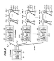
- Fig. 2 is a block diagram showing a principal construction of the electric blasting apparatus according to the invention for use in the electric blasting method according to the invention.
- a single controller 11 to a single controller 11 are connected a plurality of electric blasting devices, i.e. oscillators 13-1, 13-2, ... 13-N by means of electric wire bundles 12-1, 12-2, ... 12-N each oscillators being arranged near respective working or exploding faces.
- respective lead wires 14-1, 14-2, ... 14-N having loop portions 14A-1, 14A-2, ... 14A-N.
- loop portions 14A-1, 14A-2, ... 14A-N of lead wires 14-1, 14-2, ... 14-N are electromagnetically coupled with the loop portions 14A-1, 14A-2, ... 14A-N of lead wires 14-1, 14-2, ... 14-N.
- loop portions 16A-1, 16A-2, ... 16A-N of leg wires 16-1, 16-2, ... 16-N of electric detonators 17-1, 17-2, ... 17-N are also electromagnetically coupled with the transformer cores 15-1, 15-2, ... 15-N.
- the construction of the lead wires connected to the oscillators, the transformer cores coupled with the lead wires, the loop portions of leg wires of the electric detonators is same as that of the known method shown in Fig. 1.
- the controller 11 comprises a power source unit 18 for generating a D.C. voltage having a predetermined value, and an ignition control unit 19 for applying the D.C. voltage simultaneously or selectively to the oscillators 13-1, 13-2, ... 13-N and for transmitting ignition command simultaneously or selectively to the oscillators.
- the oscillators 13-1, 13-2, ... 13-N have the identical construction and each oscillator comprises a charge/discharge unit 20 for charging electric charge supplied from the controller 11 via the electric wire bundle and discharging the electric charge in response to the ignition command transmitted from the controller, a high frequency conversion unit 21 for converting the discharged electric charge into high frequency energy, and an oscillating unit 22 energized with the high frequency energy to generate a high frequency current.
- the D.C. voltage may be obtained by rectifying and boosting commercially available A.C. voltage of 100 volts with the aid of a known AC-DC rectifier.
- the D.C. voltage has preferably a value of 150 ⁇ 500 volts.
- the ignition control unit 19 may be formed by a switching circuit and can apply the D.C. voltage to the electric wire bundles 12-1, 12-2, ... 12-N simultaneously or selectively.
- the charge/discharge unit 20 of the oscillator includes a capacitor which is charged with the D.C. voltage applied from the controller 11 through the electric wire bundle.
- the ignition commands are supplied from the ignition control unit 19 in the controller 11 to the oscillators via the electric wire bundles 12-1, 12-2, ... 12-N. It should be noted the ignition commands may be transmitted simultaneously or selectively.
- the electric charge in the capacitors is discharged.
- the discharged electric energy is supplied to the high frequency converting units 21 and is converted thereby into the high frequency energy.
- the high frequency energy is then supplied to the oscillating unit 22 which produces the high frequency current.
- the high frequency current is supplied to the lead wires 14-1, 14-2, ... 14-N. Therefore, due to the electromagnetic induction, high frequency currents are induced in loop portions 16-1, 16-2, ...
- the single controller 11 and a plurality of oscillators 13-1, 13-2, ... 13-N are electrically connected by means of the electric wire bundles 12-1, 12-2, ... 12-N and the D.C. currents flow through the electric wire bundles. Therefore, even if the electric wire bundles are long, the transmission loss of the electric energy can be restricted to a small level and thus, a large number of electric detonators can be positively exploded. Further, a large number of oscillators 13-1, 13-2, ... 13-N can be controlled or managed by the single controller 11 in a central control mode, and therefore the working faces and their neighboring places can be completely free from workers and the blasting operation can be performed in an efficient and safe manner.
- Fig. 3 is a block diagram illustrating a whole construction of an embodiment of the electric blasting apparatus according to the invention for use in the electric blasting method according to the invention
- Fig. 4 is a circuit diagram showing a detailed construction of the controller
- Fig. 5 is a circuit diagram depicting a detailed construction of the oscillator.
- a controller 11 comprises a single power source unit 18 and a plurality of ignition control units 19-1, 19-2, ... 19-N, the number of which is equal to that of oscillators 13-1, 13-2, ... 13-N.
- the ignition control units have the identical construction and thus only the ignition control unit 19-1 will be explained hereinbelow.
- the power source unit 18 comprises a socket 41 for connecting the controller 19 to A.C. 100 V commercially available power source line, power switch 42 and a power source circuit 43.
- the power source circuit 43 has plural sets of output terminals, each being connected to respective ignition control units 19-1, 19-2, ... 19-N.
- the ignition control unit 19-1 comprises main switch 44, charge/discharge control circuit 45, charging switch 46, ignition switch 47, charge display device 48 and ignition display device 49.
- Each of electric wire bundles 12-1, 12-2, ... 12-N for connecting the ignition control units 19-1, 19-2 ... 19-N to the oscillators 13-1, 13-2, ... 13-N is formed by a harness including five electric conductors 51 ⁇ 55.
- the conductor 53 is connected to the ground, the charging current is supplied via the conductors 51 and 53, the ignition command is transmitted from the controller to the oscillator through the conductors 52 and 53, and a detection signal which is generated upon detection of the high frequency current is transmitted from the oscillator to the controller via the conductors 54 and 53. Further, the communication with telephone between the controller and oscillator can be carried out over the conductors 55 and 53.
- the oscillators 13-1, 13-2, ... 13-N have the same construction and thus only the oscillator 13-1 will be explained.
- the oscillator 13-1 comprises a charge/discharge unit 20 which stores the D.C current supplied via the conductors 51, 53 from the controller 11 and discharges the stored charge in response to the ignition command transmitted from the controller 11 over the conductors 52, 53, a high frequency converting unit 21 for converting the discharged energy into the high frequency energy, an oscillating unit 22 energized with the high frequency energy and generating the high frequency current of 70 ⁇ 110 KHz, and a current detecting circuit 23 which detects the supply of the high frequency current to the lead wire 14-1 and supplies the detection signal to the ignition control unit 19-1 via the conductors 54,53.
- Fig. 4 shows the detailed construction of the power source unit 18 shown in Fig. 3.
- the socket 41 connectable to the 100 V A.C. supply line is connected via the power switch 42 and fuse 61 to an AC-DC rectifier 62 of the power source circuit 43.
- the AC-DC rectifier 62 includes output terminals 62a ⁇ 62i at which voltages having various values are applied as illustrated in Fig. 4.
- the output terminals 62b and 62c are connected via diodes 64 and 65 to a relay 66.
- the output terminal 62a is the ground terminal and is connected to one of output terminals of a full wave rectifier 67 whose input terminals are connected to the output terminals 62d and 62e of the rectifier 62.
- the other output terminal of the full wave rectifier 67 is connected to one terminal of a capacitor 68 the other terminal of which is connected to a ground line 69 connected to the output terminal 62a.
- Across the ground line 69 and the relay 66 is connected a capacitor 70.
- a junction point between the relay 66 and capacitor 70 is connected via a resistor 71 to a collector of a transistor 73 whose base is connected via a resistor 72 to the collector.
- the base of transistor 73 is connected to the ground line 69 by means of a varistor 74.
- a resistor 75 is connected in parallel with the capacitor 68.
- An emitter of transistor 73 is connected to the main switch 44 via a resistor 71A.
- the charge/discharge control circuit 45 includes a short-circuiting switch 76 which is actuated in conjunction with the main switch 44.
- the main switch 44 is connected via relay 77, fuse 78 and resistor 79 to the charging switch 66.
- To the ground line 69 connected to the ground conductor 53 are connected one terminal of resistors 81 and 82.
- the other end of the resistor 81 is connected to a base of transistor 80 and the other end of resistor 82 is connected by means of a neon tube 83 to the other end of resistor 81 and at the same time is connected via a resistor 84 to a junction point between the fuse 78 and resistor 79.
- a collector of transistor 80 is connected through a contact 86 driven by the relay 77, resistor 87 and charge display device 48 is composed of a light emitting diode to the ignition switch 47 connected to the conductor 52.
- Across the output terminals 62f and 62g of the AC-DC rectifier 62 is connected a series circuit of diode 88 and capacitor 89, and this capacitor 89 is connected to an IC regulator 90.
- Across output terminals of the IC regulator 90 is connected a capacitor 91 whose terminals are connected to output lines 92 and 93 to generate a regulated D.C. voltage of 6 V across the output lines.
- To the output lines is connected a communication circuit 94 to which is further connected a telephone set 95 which is connectable via the conductors 55 and 53 to telephone sets provided in respective oscillators 13-1 ⁇ 13-N.
- Fig. 5 is a circuit diagram showing the detailed construction of the oscillator 13-1.
- the charging/discharging unit 20 includes a relay 101 connected across the conductors 52 and 53, relay contacts 102, 103 driven by the relay 101 and a capacitor 104.
- Fig. 5 represents the condition prior to or during the charging, and the capacitor 104 is connected across the conductors 51 and 53.
- the high frequency conversion unit 21 comprises four switching transistors 105 ⁇ 108, resistors 110 ⁇ 113 each connected across bases of respective transistors and a conductor 109, resistors 114 ⁇ 117 each connected to bases of respective transistors, resistors 118, 119, a varistor 120 connected across collectors of transistors 105, 106 and the conductor 109, a varistor 121 connected across collectors of transistors 107, 108 and the conductor 109, a coil 122 forming a transformer together with a coil 126, a resistor 123 and capacitors 124, 125.
- the resistor 118 is connected across commonly coupled emitters of transistors 105, 107 and the conductor 109, and the resistor 119 is connected across commonly coupled emitters of transistors 106, 108 and the conductor 109.
- the resistor 123 and capacitor 124 are connected in a series circuit which is connected between the relay contacts 102 and 103 of the charging/discharging unit 20, and the capacitor 125 is connected across the series circuit of the resistor 123 and capacitor 124.
- a junction point of the resistor 123 and capacitor 124 is connected to a middle tap of the coil 122 whose both ends are connected to commonly coupled one terminals of resistors 114, 115 and to commonly coupled one terminal of resistors 116, 117.
- the oscillating unit 22 includes the coil 126 of the transformer and a capacitor 127 connected in parallel with the coil 126, and supplies the high frequency current of the lead wire 14-1 connected to output terminals 128 and 129.
- the current detection circuit 23 comprises a coil 130 electromagnetically coupled with the output line of the oscillation unit 22, a diode 131 connected to the coil, a capacitor 132, and resistors 133, 134.
- the detection signal is supplied to the controller 11 via the conductors 54 and 53.
- the oscillator further includes a telephone set 135 connected to the conductors 55, 53 so that the communication can be established between the telephone set 95 provided in the controller 11.
- the power switch 42 of the power source unit 18 in the controller 11 is closed to generate given voltages at the output terminals 62a ⁇ 62i of the AC-DC rectifier 62 in the power source circuit 43.
- the main switch 44 in the ignition control unit 19-1 is closed and at the same time the switch 76 is opened.
- the D.C. voltage of 400 V generated across the output terminals 62b, 62c and 62a are applied to the conductors 51 and 53 by means of the relay 66, resistor 71, transistor 73, resistor 71A, switch 44, relay 77, fuse 78, resistor 79 and switch 46.
- the capacitor 104 provided in the charging/discharging unit 20 of the oscillator 13-1 is charged. Since the relay 77 is energized, its contact 86 is closed and a voltage corresponding to the terminal voltage of capacitor 104 is applied to the neon tube 83. When the voltage across the capacitor 104 is remained low, the voltage across the neon tube 83 is also low so that the neon tube is non-conductive. Therefore, the base potential of the transistor 80 is remained low and thus the transistor is remained non-conductive and the light emitting diode 48 in the ignition control unit 19-1. When the voltage across the capacitor 104 is increased, the neon lamp 83 becomes conductive and the base potential of the transistor 80 is also increased.
- the transistor 80 becomes conductive and the light emitting diode 48 is lighted on.
- the operator operating the controller 11 can check whether the capacitor 104 provided in the oscillator 13-1 located far from the controller has been charged up to a predetermined voltage by monitoring the condition of the light emitting diode 48 provided in the controller 11.
- the switch 46 After confirming the charging up of the capacitor 104 by watching the light emitting diode 48, the switch 46 is opened to disconnect the capacitor 104 from the charging circuit and at the same time the switch 47 is closed to apply the D.C. voltage of 23 V appearing across the output terminals 62d and 62e to the conductors 52 and 53. Then the relay 101 in the charging/discharging unit 20 is energized and its contacts 102 and 103 are changed into positions opposite to those shown in Fig. 5. Then the charge stored in the capacitor 104 is discharged into the high frequency conversion unit 21.
- the high frequency conversion unit 21 constitutes a transistor type inverter and the transistor pairs 105, 106 and 107, 108 are made conductive alternately.
- the current passes through upper and lower halves of the primary coil 122 in opposite directions, and thus the high frequency current having a frequency determined by the LC resonance circuit of the oscillation unit 22 is induced in the secondary coil 126.
- the high frequency current thus generated is supplied to the lead wire 14-1 via the output terminals 128, 129.
- the high frequency current passes, the high frequency current is induced in the coil 130 of the current detection circuit 23.
- the induced high frequency current is rectified by the diode 131 to generate the D.C. detection signal which is supplied via the conductors 54, 53 to the controller 11. Then the light emitting diode 49 in the ignition control unit 19-1 is energized to light on.
- the capacitor 104 in the condition in which the oscillator 13-1 is connected to the controller 11 via the conductor bundle 12-1, the capacitor 104 is short-circuited by the switch 76 provided in the controller, the capacitor could not be erroneously charged to cause any accident. Further, after the main switch 44 has been closed to initiate to charge the capacitor, when it is required to stop the explosion due to any reason, the main switch 44 is opened and the switch 76 is closed to short-circuit the capacitor 104 to discharge the charge stored in the capacitor. In this manner, the explosion can be carried out in a very safe manner.
- the ignition control units 19-1 ⁇ 19-N By effecting the above mentioned operation for ignition control units 19-1 ⁇ 19-N corresponding to the oscillators 13-1 ⁇ 13-N, it is possible to blast the detonators at a plurality of working faces in a centrally controllable manner.
- the ignition control units may be operated separately or all the capacitor 104 in all the oscillators 13-1 ⁇ 13-N are first charged and then the ignition switches 47 in the ignition control units 19-1 ⁇ 19-N may be actuated separately.
- One controller 11 shown in Fig. 4 and ten oscillators 13-1 ⁇ 13-10 illustrated in Fig. 5 were used.
- the oscillators were designed to generate the high frequency current of about 100 KHz.
- the controller 11 was energized with the commercially available A.C. 100 V.
- Each of wire bundles 12-1 ⁇ 12-10 for connecting the oscillators to the controller was constructed by a harness including five conductors each having a cross sectional area of about 0.75 mm2 (0.02 ⁇ /m).
- the wire bundles had the lengths shown in table 1.
- lead wires 14-1 ⁇ 14-10 respectively having lengths represented in the table, each lead wire being formed by the low impedance lead wire manufactured by Nippon Oil and Fats Company, Limited.
- auxiliary lead wires each having a length of 50 m and a loop portion.
- Forty transformer cores 15 were coupled with each loop portion and to each transformer core were coupled five electric detonators having a leg wire of 3.0 m length.
- the transformer core was formed by a rectangular core having a side length of 15 mm and a thickness of 10 mm.
- the ten oscillators were controlled by the controller and the detonators were exploded by supplying the high frequency currents to the lead wires. The result is shown in the table.
- the transformer cores are electromagnetically coupled with the loop portions of auxiliary lead wire, but they may be coupled with the loop portion of main lead wire.
- the completion of charging and the generation of the high frequency current can be monitored at the controller, if these faculties are not required, the charging display, ignition display, current detection circuit and conductors for the detection signal may be all deleted.
- the wire bundle may be formed by a harness with three conductors.
- the harness may include only two conductors.
- the oscillator generates the high frequency current which is transferred to the leg wire of detonator via the transfer core, but it is also possible to discharge the electric charge stored in the oscillator toward the leg wire of detonator directly. In such a case the leg wire is directly connected to the discharging circuit of the capacitor.
- a plurality of the oscillators each arranged near respective working faces can be controlled by the single controller arranged far from the working faces, so that the large scale explosion can be performed in a positive and safe manner. That is to say, all the working faces can be free from the workers and thus the problem of the after-gas can be effectively solved.
- the controller and oscillators are connected via the wire bundles and the oscillators are energized with the D.C. current, so that the electric energy can be efficiently transferred through the long wire bundles up to several kilometers with a very small loss and the electric detnators can be positively exploded.
Landscapes
- Engineering & Computer Science (AREA)
- General Engineering & Computer Science (AREA)
- Ignition Installations For Internal Combustion Engines (AREA)
- Supply And Distribution Of Alternating Current (AREA)
- Charge And Discharge Circuits For Batteries Or The Like (AREA)
- Generation Of Surge Voltage And Current (AREA)
- Air Bags (AREA)
- Electrical Discharge Machining, Electrochemical Machining, And Combined Machining (AREA)
- Control Of Electric Motors In General (AREA)
Applications Claiming Priority (2)
| Application Number | Priority Date | Filing Date | Title |
|---|---|---|---|
| JP61292556A JPS63148100A (ja) | 1986-12-10 | 1986-12-10 | 集中管理電磁誘導式電気発破装置 |
| JP292556/86 | 1986-12-10 |
Publications (2)
| Publication Number | Publication Date |
|---|---|
| EP0274231A1 true EP0274231A1 (fr) | 1988-07-13 |
| EP0274231B1 EP0274231B1 (fr) | 1990-10-03 |
Family
ID=17783293
Family Applications (1)
| Application Number | Title | Priority Date | Filing Date |
|---|---|---|---|
| EP87310768A Expired EP0274231B1 (fr) | 1986-12-10 | 1987-12-08 | Méthode pour faire sauter électriquement plusieurs détonateurs et appareil électrique de sautage utilisant cette méthode |
Country Status (6)
| Country | Link |
|---|---|
| US (1) | US4848232A (fr) |
| EP (1) | EP0274231B1 (fr) |
| JP (1) | JPS63148100A (fr) |
| AU (1) | AU591369B2 (fr) |
| CA (1) | CA1288503C (fr) |
| DE (1) | DE3765405D1 (fr) |
Cited By (1)
| Publication number | Priority date | Publication date | Assignee | Title |
|---|---|---|---|---|
| EP1482271A1 (fr) * | 2003-05-26 | 2004-12-01 | Vitzrotech Co., Ltd. | Appareil pour fournir de l'énergie électrique à une cartouche explosive |
Families Citing this family (27)
| Publication number | Priority date | Publication date | Assignee | Title |
|---|---|---|---|---|
| US5214236A (en) * | 1988-09-12 | 1993-05-25 | Plessey South Africa Limited | Timing of a multi-shot blast |
| US4986183A (en) * | 1989-10-24 | 1991-01-22 | Atlas Powder Company | Method and apparatus for calibration of electronic delay detonation circuits |
| JPH0694996B2 (ja) * | 1989-11-24 | 1994-11-24 | 繁明 國友 | 花火点火装置 |
| US5295438A (en) * | 1991-12-03 | 1994-03-22 | Plessey Tellumat South Africa Limited | Single initiate command system and method for a multi-shot blast |
| DE4225330C1 (de) * | 1992-07-31 | 1993-11-04 | Bergwerksverband Gmbh | Vorrichtung zum sequentiellen zuenden von elektrischen zuendern |
| GB9423314D0 (en) * | 1994-11-18 | 1995-01-11 | Explosive Dev Ltd | Electrical distribution system |
| US5756926A (en) * | 1995-04-03 | 1998-05-26 | Hughes Electronics | EFI detonator initiation system and method |
| US5767437A (en) * | 1997-03-20 | 1998-06-16 | Rogers; Donald L. | Digital remote pyrotactic firing mechanism |
| US6470803B1 (en) | 1997-12-17 | 2002-10-29 | Prime Perforating Systems Limited | Blasting machine and detonator apparatus |
| US6490977B1 (en) | 1998-03-30 | 2002-12-10 | Magicfire, Inc. | Precision pyrotechnic display system and method having increased safety and timing accuracy |
| US20060086277A1 (en) * | 1998-03-30 | 2006-04-27 | George Bossarte | Precision pyrotechnic display system and method having increased safety and timing accuracy |
| US6729240B1 (en) * | 2002-11-26 | 2004-05-04 | The Boeing Company | Ignition isolating interrupt circuit |
| US7107908B2 (en) * | 2003-07-15 | 2006-09-19 | Special Devices, Inc. | Firing-readiness diagnostic of a pyrotechnic device such as an electronic detonator |
| US7286333B2 (en) * | 2004-10-28 | 2007-10-23 | The Boeing Company | Switch card apparatus and methods |
| US8079307B2 (en) | 2005-10-05 | 2011-12-20 | Mckinley Paul | Electric match assembly with isolated lift and burst function for a pyrotechnic device |
| US20080282925A1 (en) * | 2007-05-15 | 2008-11-20 | Orica Explosives Technology Pty Ltd | Electronic blasting with high accuracy |
| NZ592333A (en) | 2008-10-24 | 2014-10-31 | Battelle Memorial Institute | Electronic detonator system |
| US8477049B2 (en) * | 2009-06-05 | 2013-07-02 | Apple Inc. | Efficiently embedding information onto a keyboard membrane |
| CN102538602B (zh) * | 2010-12-21 | 2014-07-16 | 贵州久联民爆器材发展股份有限公司 | 电子雷管振荡延时的方法及装置 |
| GB201207450D0 (en) * | 2012-04-26 | 2012-06-13 | Secr Defence | An electrical pulse splitter for an explosives system |
| JP2014092316A (ja) * | 2012-11-02 | 2014-05-19 | Ihi Aerospace Co Ltd | ロケット用の点火装置とその使用方法 |
| US9759538B2 (en) * | 2016-02-12 | 2017-09-12 | Utec Corporation, Llc | Auto logging of electronic detonators |
| JP2018146126A (ja) * | 2017-03-01 | 2018-09-20 | 日油株式会社 | 送電装置及び無線起爆システム |
| US10466026B1 (en) | 2018-07-25 | 2019-11-05 | Utec Corporation Llc | Auto logging of electronic detonators using “smart” insulation displacement connectors |
| JP7172594B2 (ja) * | 2018-12-28 | 2022-11-16 | 日油株式会社 | 水底または海底を掘削するための発破システムおよび発破方法 |
| CN110174030B (zh) * | 2019-06-26 | 2023-11-21 | 新疆工程学院 | 一种射孔用磁电雷管起爆信号的检测装置 |
| CN112924800B (zh) * | 2021-03-06 | 2022-08-12 | 中北大学 | 电压连续可调式电爆炸箔伏安特性测试装置及充放电方法 |
Citations (6)
| Publication number | Priority date | Publication date | Assignee | Title |
|---|---|---|---|---|
| US3750586A (en) * | 1971-06-25 | 1973-08-07 | Us Navy | Firing device |
| US3757697A (en) * | 1972-02-02 | 1973-09-11 | Bendix Corp | Remotely controlled blasting machine |
| DE2356875A1 (de) * | 1973-11-14 | 1975-05-15 | Siemens Ag | Schaltungsanordnung zum erzeugen zeitlich aufeinanderfolgender stromstoesse |
| GB2079907A (en) * | 1980-06-28 | 1982-01-27 | Dynamit Nobel Ag | Arrangement for the contactless transmission of electrical energy to an element to be contacted thereby |
| EP0096482A2 (fr) * | 1982-06-03 | 1983-12-21 | Imperial Chemical Industries Plc | Dispositif et procédé d'initiation d'explosions |
| US4601243A (en) * | 1983-10-19 | 1986-07-22 | Nippon Oil And Fats Company, Limited | Method and apparatus for electrically detonating blasting primers |
Family Cites Families (4)
| Publication number | Priority date | Publication date | Assignee | Title |
|---|---|---|---|---|
| US3752081A (en) * | 1971-11-23 | 1973-08-14 | Bendix Corp | Blasting machine |
| DE2945122A1 (de) * | 1978-02-01 | 1980-05-22 | Ici Ltd | Elektrische verzoegerungsvorrichtung |
| IN152055B (fr) * | 1978-05-24 | 1983-10-08 | Ici Plc | |
| JPS60111900A (ja) * | 1983-11-22 | 1985-06-18 | 日本油脂株式会社 | 遠隔制御段発発破装置 |
-
1986
- 1986-12-10 JP JP61292556A patent/JPS63148100A/ja active Granted
-
1987
- 1987-12-07 US US07/129,136 patent/US4848232A/en not_active Expired - Lifetime
- 1987-12-08 DE DE8787310768T patent/DE3765405D1/de not_active Expired - Lifetime
- 1987-12-08 EP EP87310768A patent/EP0274231B1/fr not_active Expired
- 1987-12-08 AU AU82216/87A patent/AU591369B2/en not_active Ceased
- 1987-12-09 CA CA000553928A patent/CA1288503C/fr not_active Expired - Lifetime
Patent Citations (6)
| Publication number | Priority date | Publication date | Assignee | Title |
|---|---|---|---|---|
| US3750586A (en) * | 1971-06-25 | 1973-08-07 | Us Navy | Firing device |
| US3757697A (en) * | 1972-02-02 | 1973-09-11 | Bendix Corp | Remotely controlled blasting machine |
| DE2356875A1 (de) * | 1973-11-14 | 1975-05-15 | Siemens Ag | Schaltungsanordnung zum erzeugen zeitlich aufeinanderfolgender stromstoesse |
| GB2079907A (en) * | 1980-06-28 | 1982-01-27 | Dynamit Nobel Ag | Arrangement for the contactless transmission of electrical energy to an element to be contacted thereby |
| EP0096482A2 (fr) * | 1982-06-03 | 1983-12-21 | Imperial Chemical Industries Plc | Dispositif et procédé d'initiation d'explosions |
| US4601243A (en) * | 1983-10-19 | 1986-07-22 | Nippon Oil And Fats Company, Limited | Method and apparatus for electrically detonating blasting primers |
Cited By (1)
| Publication number | Priority date | Publication date | Assignee | Title |
|---|---|---|---|---|
| EP1482271A1 (fr) * | 2003-05-26 | 2004-12-01 | Vitzrotech Co., Ltd. | Appareil pour fournir de l'énergie électrique à une cartouche explosive |
Also Published As
| Publication number | Publication date |
|---|---|
| AU8221687A (en) | 1988-06-16 |
| JPS63148100A (ja) | 1988-06-20 |
| DE3765405D1 (de) | 1990-11-08 |
| AU591369B2 (en) | 1989-11-30 |
| EP0274231B1 (fr) | 1990-10-03 |
| JPH0350200B2 (fr) | 1991-07-31 |
| CA1288503C (fr) | 1991-09-03 |
| US4848232A (en) | 1989-07-18 |
Similar Documents
| Publication | Publication Date | Title |
|---|---|---|
| EP0274231B1 (fr) | Méthode pour faire sauter électriquement plusieurs détonateurs et appareil électrique de sautage utilisant cette méthode | |
| CA1306768C (fr) | Energiseur de cloture electrique | |
| US2331058A (en) | Firing apparatus for gun perforators | |
| US3757697A (en) | Remotely controlled blasting machine | |
| CA2147016A1 (fr) | Ballast a circuit d'amorcage compact pour lampe a decharge | |
| EP0750396A2 (fr) | Générateur d'impulsions à tension élévée | |
| GB2061035A (en) | Plasma torch power supply circuit | |
| US4601243A (en) | Method and apparatus for electrically detonating blasting primers | |
| EP0252889A2 (fr) | Méthode et montage de commande de magnétrons | |
| US5458063A (en) | Demining device | |
| US6732656B1 (en) | High voltage tolerant explosive initiation | |
| US5550434A (en) | Boost-mode energization and modulation circuit for an arc lamp | |
| US5877949A (en) | Direct capacitive discharge electric fence controller | |
| CN111023923A (zh) | 磁电雷管起爆控制电路 | |
| CA1326068C (fr) | Systeme d'amorcage de detonateur | |
| US2050135A (en) | Electrical circuits for gas-discharge tubes | |
| US4847535A (en) | Hybrid ballast for multiple discharge lamps | |
| US2823678A (en) | Diathermy power controls | |
| US2253185A (en) | Electric discharge apparatus | |
| US5596281A (en) | Method and an apparatus for measuring the output voltage on an electric fence and for producing electric pulses in said fence | |
| US2513396A (en) | Ionization system for gaseous conduction lamps | |
| US4634932A (en) | Lighting system | |
| JPH0799320B2 (ja) | 電磁誘導式電気発破装置 | |
| US2469913A (en) | Electronic flash tube apparatus | |
| RU185626U1 (ru) | Волоконно-оптическое устройство дистанционного управления взрывом |
Legal Events
| Date | Code | Title | Description |
|---|---|---|---|
| PUAI | Public reference made under article 153(3) epc to a published international application that has entered the european phase |
Free format text: ORIGINAL CODE: 0009012 |
|
| AK | Designated contracting states |
Kind code of ref document: A1 Designated state(s): DE FR GB SE |
|
| 17P | Request for examination filed |
Effective date: 19881201 |
|
| 17Q | First examination report despatched |
Effective date: 19890720 |
|
| GRAA | (expected) grant |
Free format text: ORIGINAL CODE: 0009210 |
|
| AK | Designated contracting states |
Kind code of ref document: B1 Designated state(s): DE FR GB SE |
|
| ET | Fr: translation filed | ||
| REF | Corresponds to: |
Ref document number: 3765405 Country of ref document: DE Date of ref document: 19901108 |
|
| PLBE | No opposition filed within time limit |
Free format text: ORIGINAL CODE: 0009261 |
|
| 26N | No opposition filed | ||
| EAL | Se: european patent in force in sweden |
Ref document number: 87310768.4 |
|
| PGFP | Annual fee paid to national office [announced via postgrant information from national office to epo] |
Ref country code: SE Payment date: 19991207 Year of fee payment: 13 |
|
| PGFP | Annual fee paid to national office [announced via postgrant information from national office to epo] |
Ref country code: GB Payment date: 19991208 Year of fee payment: 13 Ref country code: FR Payment date: 19991208 Year of fee payment: 13 |
|
| PGFP | Annual fee paid to national office [announced via postgrant information from national office to epo] |
Ref country code: DE Payment date: 19991210 Year of fee payment: 13 |
|
| PG25 | Lapsed in a contracting state [announced via postgrant information from national office to epo] |
Ref country code: GB Free format text: LAPSE BECAUSE OF NON-PAYMENT OF DUE FEES Effective date: 20001208 |
|
| PG25 | Lapsed in a contracting state [announced via postgrant information from national office to epo] |
Ref country code: SE Free format text: LAPSE BECAUSE OF NON-PAYMENT OF DUE FEES Effective date: 20001209 |
|
| GBPC | Gb: european patent ceased through non-payment of renewal fee |
Effective date: 20001208 |
|
| EUG | Se: european patent has lapsed |
Ref document number: 87310768.4 |
|
| PG25 | Lapsed in a contracting state [announced via postgrant information from national office to epo] |
Ref country code: FR Free format text: LAPSE BECAUSE OF NON-PAYMENT OF DUE FEES Effective date: 20010831 |
|
| REG | Reference to a national code |
Ref country code: FR Ref legal event code: ST |
|
| PG25 | Lapsed in a contracting state [announced via postgrant information from national office to epo] |
Ref country code: DE Free format text: LAPSE BECAUSE OF NON-PAYMENT OF DUE FEES Effective date: 20011002 |