EP0274255B1 - Vorrichtung zum Abspielen einer Videoplatte und Verfahren zum Wiedergeben der Videoinformation - Google Patents
Vorrichtung zum Abspielen einer Videoplatte und Verfahren zum Wiedergeben der Videoinformation Download PDFInfo
- Publication number
- EP0274255B1 EP0274255B1 EP87311064A EP87311064A EP0274255B1 EP 0274255 B1 EP0274255 B1 EP 0274255B1 EP 87311064 A EP87311064 A EP 87311064A EP 87311064 A EP87311064 A EP 87311064A EP 0274255 B1 EP0274255 B1 EP 0274255B1
- Authority
- EP
- European Patent Office
- Prior art keywords
- video
- video information
- disk
- information
- player
- Prior art date
- Legal status (The legal status is an assumption and is not a legal conclusion. Google has not performed a legal analysis and makes no representation as to the accuracy of the status listed.)
- Revoked
Links
- 238000000034 method Methods 0.000 title claims description 31
- 239000002131 composite material Substances 0.000 claims description 16
- 238000001514 detection method Methods 0.000 claims description 5
- 230000001360 synchronised effect Effects 0.000 description 8
- 230000003287 optical effect Effects 0.000 description 4
- 238000012545 processing Methods 0.000 description 4
- 238000000926 separation method Methods 0.000 description 4
- 230000005236 sound signal Effects 0.000 description 4
- 230000005540 biological transmission Effects 0.000 description 3
- 239000003990 capacitor Substances 0.000 description 2
- 230000006866 deterioration Effects 0.000 description 2
- 230000000694 effects Effects 0.000 description 2
- 238000000605 extraction Methods 0.000 description 2
- 238000001228 spectrum Methods 0.000 description 2
- 238000012546 transfer Methods 0.000 description 2
- 230000000007 visual effect Effects 0.000 description 2
- 230000002411 adverse Effects 0.000 description 1
- 238000012937 correction Methods 0.000 description 1
- 239000013078 crystal Substances 0.000 description 1
- 230000007812 deficiency Effects 0.000 description 1
- 239000000284 extract Substances 0.000 description 1
- 230000006870 function Effects 0.000 description 1
- 230000000977 initiatory effect Effects 0.000 description 1
- 238000012544 monitoring process Methods 0.000 description 1
- 239000000725 suspension Substances 0.000 description 1
Images




Classifications
-
- H—ELECTRICITY
- H04—ELECTRIC COMMUNICATION TECHNIQUE
- H04N—PICTORIAL COMMUNICATION, e.g. TELEVISION
- H04N5/00—Details of television systems
- H04N5/76—Television signal recording
- H04N5/91—Television signal processing therefor
- H04N5/93—Regeneration of the television signal or of selected parts thereof
-
- H—ELECTRICITY
- H04—ELECTRIC COMMUNICATION TECHNIQUE
- H04N—PICTORIAL COMMUNICATION, e.g. TELEVISION
- H04N9/00—Details of colour television systems
- H04N9/79—Processing of colour television signals in connection with recording
- H04N9/80—Transformation of the television signal for recording, e.g. modulation, frequency changing; Inverse transformation for playback
- H04N9/802—Transformation of the television signal for recording, e.g. modulation, frequency changing; Inverse transformation for playback involving processing of the sound signal
Definitions
- the present invention relates to a method of reproducing video information recorded on an information recording disk.
- the inventive method includes a method of compensating for conditions in the disk and the disk player, as will be explained below.
- compact disks Digital audio disks as small as 12 cm in diameter (called compact disks) are known, and have been used for recording digital audio information.
- disks known as composite disks, which are the same size as a compact disk, have been developed, which contain both a frequency-modulated video signal and a pulse code modulation (PCM) signal which are superposed.
- PCM pulse code modulation
- a first region 1a in an inner portion of the composite disk is referred to as a CD region.
- PCM audio information is recorded in this internal portion 1a.
- an outer portion 1b referred to as a video region a frequency-modulated video signal and PCM audio signal are superposed for purposes of recording in that region.
- the frequency spectrum of the signal recorded in the video region 1b is shown in Figure 4.
- the video signal includes an element having a frequency higher than that of the PCM signal.
- region A corresponds to the PCM signal
- region B corresponds to the video FM signal.
- disk rotation might be several hundred rpm in the CD region 1a, but between 1000 and 3000 revolution per minute (rpm) in the video region 1b.
- the rotational speed might be 2000 and several hundred rpm at the innermost track in the region 1b, and 1000 and several hundred rpm at the outermost track in the region 1b.
- the difference in rotational speed necessary between the CD region 1a and the video region 1b is of particular significance when a search operation is to be carried out which crosses over the boundary between the CD region and the video region during a reproducing operation on the composite disk.
- some length of time (settling time ⁇ is required.
- a search operation crossing over the two different regions can take longer than a search which would be carried out only in one of the two regions.
- another source of noise, or otherwise poor reproduction in a video disk might be a failure of the disk player itself, such as an unexpected power failure during reproduction of signals recorded in the video region. It is possible that reproduction might be suspended for some other reason as well. In such an event, it is necessary to restart reproduction by turning the power switch of the device on. Again, because of the relatively rapid rotation of the disk necessary for reproduction of the video signal, a longer rise time is required until the number of rotations is stabilized. During this rise time, video information is not input to the television monitor for a relatively long time, thereby possibly causing noise to be generated on the television screen, again causing deterioration of visual recognition.
- a disk player which reproduces video information stored on an information recording disk, the player comprising means for receiving, during reproduction of the video information from the information recording disk, an instruction to initiate a search; means for determining, when the search has been initiated, whether a field of the video information has been stored in a video memory of the player; and means for reading out the field of video information stored in the video memory repeatedly until the search is complete, provided that a field of video information has been stored in the video memory.
- a disk player for reproducing video information stored on an information recording disk, the player comprising a video memory for storing at least one field of video information; a main power supply; a backup power supply which provides power to the video memory during interruption of the main power supply; means for storing in the video memory, during a reproducing operation in which the video information is reproduced by the disk player from the information recording disk, a most recent field of video information; and means for repeatedly reading the field of video information stored in the video memory during an off condition of the main power supply, and for repeatedly reading the field of video information, even after detection of an on condition of the main power supply, during reinitialization of the disk player, until the reinitialisation is complete.
- the invention also includes methods using such apparatus.
- Figure 1A shows circuitry and structure for a disk player to which the search method of the present invention may be applied.
- a disk 1 is driven by a spindle motor 2.
- Information recorded on the disk is read by an optical pickup 3, which comprises an optical system including a laser diode, an object lens, a photodetector, a focus actuator which drives the object lens in the direction of its optical axis, and a tracking actuator which biases an information detecting spot issued from the pickup 3 in the radial direction of the disk.
- the pickup 3 is mounted on a slider 4 which moves freely in the radial direction of the disk.
- the slider 4 is driven in a straight line by a slider motor 5, and a transmission mechanism 6 which may be a combination of a rack and pinion, as shown in the drawing.
- a high frequency RF signal read out from the pickup 3 is supplied to a video information demodulating system 8 and a digital information demodulating system 9 through an RF amplifier 7.
- the signal from the RF amplifier 7 is demodulated into a video signal by a demodulator 10.
- the output of the demodulator 10 is supplied to a time base correcting circuit 11 and a separation circuit 12.
- the separation circuit 12 separates and extracts the horizontal synchronous signal H, the vertical synchronous signal V, and control data which is included in the video signal.
- the time base correcting circuit 11 is formed by a variable delay element, such as a charge coupled device (CCD).
- the circuit 11 corrects the time base error by varying the delay of the variable delay element in accordance with the control signal received from a time base control circuit 13.
- the time base control circuit 13 receives the output of a voltage controlled oscillator 14 and provides that output, and a divided output thereof.
- the crystal controlled oscillator 14 oscilates in synchronization with the horizontal synchronous signal which is separated and extracted by the separation circuit 12 and with the control signal, in accordance with a phase difference between the horizontal synchronous signal as output by the time base correcting circuit 11 and a color burst signal.
- One example of appropriate structure for the control circuit 13 is disclosed in Japanese Published Patent Application No. JP-A-56 102182/1981.
- the output of the time base correcting circuit 11 is provided as an input of a selector switch 15, and also is supplied to an analog-to-digital (A/D) converter 17 through a low pass filter (LPF) 16.
- A/D converter 17 the video signal is sampled within a predetermined period. The resultant sample values are converted sequentially to digital data.
- the output of the A/D converter 17 is supplied to a video memory 18, which may be a random access memory (RAM), and other necessary associated components, which are well known to those of ordinary skill in the relevant technological field.
- the video memory 18 must be large enough to store at least one field of video information.
- a memory control circuit 19 provides address control and mode control for the video memory 18.
- the circuit 19 provides structure for realizing control so that data written into respective addresses of the video memory 18 may be read sequentially in accordance with an output of a reference clock generating circuit 20.
- the respective addresses of the video memory 18 then may be rewritten in accordance with a write enable signal W output from a system controller 21, as will be described below.
- the data read from the video memory 18 is converted to an analog signal by a digital-to-analog (D/A) converter 22, and then is provided as the other input of the selection switch 15 through LPF 23.
- the selection switch 15 usually is set to the side a, as shown in the figure, so that the video signal output from the time base correcting circuit 11 may be supplied directly to the video output terminal 24.
- the selection switch 15 is set to the side b, in accordance with the switching instruction sent from the system controller 21, the signal from the video memory 18 is selected and supplied to the video output terminal 24.
- the digital information demodulation system 9 is provided with a selection switch 25 which is set depending on whether the information to be reproduced is found in the CD region 1a or video region 1b of the composite disk 1 ( Figure 3).
- the switch 25 is set to side a during reproduction of signals recorded in the CD region 1a, or the side b during reproduction of signals recorded in the video region 1b.
- the switching operation of the switch 25 is carried out in accordance with an instruction issued from the system controller 21.
- the rotational speed of the disk is very different, depending on whether it is the CD region or the video region which is having information reproduced from it.
- This difference in rotational speed is shown graphically in Figure 5.
- the PCM signal is an eight to fourteen modulation (EFM) signal
- EFM eight to fourteen modulation
- the demodulation system is used in common by switching the signal processing system for the reproduced EFM signal between circuitry for the CD region and circuitry for the video region.
- the reproduced RF signal is an EFM signal
- the detected EFM signal is passed to an equalizer circuit 26 having predetermined equalizing characteristics, to provide frequency compensation.
- the output of equalizer 26 is passed to an amplifier 27 having a predetermined gain.
- the EFM signal included in the reproduced RF signal, together with the FM video signal are extracted by an EFM extraction circuit 28 which includes an LPF and other appropriate circuitry which would be known to those of ordinary skill in the relevant technological field.
- the output of the EFM extraction circuit 28 is passed to an equalizer circuit 29 which performs frequency compensation, the equalizer circuit 29 having a different characteristic from that of the circuit 26.
- the output of the equalizer 29, is passed to an amplifier 30 having a gain larger than that of amplifier 27.
- the output of the selector switch 25 is supplied to a demodulating/correcting circuit 31, which demodulates the EFM signal for writing to memory, such as a RAM.
- the circuit 31 also controls the memory in accordance with a clock signal provided by a reference clock generator 32.
- the circuit 31 further executes a deinterleaving operation through processing of data, and error correction using parity included in the data, and further detects control information.
- the digital audio signal which is output by the demodulating and correcting circuit 31 is processed by an audio signal processing circuit 33 which comprises a D/A converter and a deglitcher circuit.
- the output of the circuit 33 then is supplied to appropriate ones of audio output terminals 34L, 34R corresponding to left and right channels, respectively.
- a position detector 35 is provided in the vicinity of the path of the pickup 3, to detect whether the beam emitted from the pickup 3 has reached a radial position corresponding to a vicinity of the boundary between the CD region 1a and video region 1b in the composite disk.
- the position detector 35 generates an appropriate detection signal accordingly. The generation of that signal indicates that the pickup 3 has reached the video region 1b.
- Any appropriate detector, such as an optical sensor, may be used, and such detectors have well known structures.
- the output of the detector 35 also is supplied to the system controller 21.
- the system controller 21 comprises a microcomputer which includes a central processing unit (CPU), read only memory (ROM), and a random access memory (RAM).
- CPU central processing unit
- ROM read only memory
- RAM random access memory
- the horizontal and vertical synchronous signals and the control data output by the separation circuit 12, as well as control data output by the demodulating/correcting circuit 31 are provided to the system controller 21.
- Other information provided to the system controller 21 includes information which identifies whether a compact disk or a composite disk is being used in the disk player, and information which indicates whether only the CD region 1a or the video region 1b, or both regions are to have information reproduced therefrom during a reproducing operation.
- the CPU of the system controller 21 processes the input information (input signal) in accordance with a program previously stored in the ROM to control portions of the disk player such as a drive circuit (not shown) which drives the selection switches 15, 25; memory control circuit 19; spindle motor 2; the drive circuit 37 which drives the slider motor; and a display portion 38, among other elements.
- a drive circuit (not shown) which drives the selection switches 15, 25; memory control circuit 19; spindle motor 2; the drive circuit 37 which drives the slider motor; and a display portion 38, among other elements.
- FIG. 1A Also shown in Figure 1A is an operation section 36, through which a user inputs operational commands to the disk player via the system controller 21.
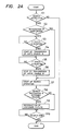
- the CPU determines whether a search instruction has been issued (an address search, step S1). If a search instruction has not yet been issued, operation returns to the routine which was being executed immediately before the calling of the subroutine illustrated in Figure 2A. If a search instruction has been issued, then it is determined whether a reproducing operation is to be carried out in the video region 1b (step S2).
- step S3 is executed repeatedly until a vertical synchronous signal is detected, at which point transmission of the write enable signal W is started (step S4).
- the vertical synchronous signal is again looked for (step S5) and this step is repeated until the signal is detected.
- transmission of the write enable signal W is stopped (step S6).
- step S7 Upon starting of the search operation in step S7, it is determined whether the searching destination is set to a region different from the starting region (step S8) if the destination is different (in the case of searching in a video region, this would be the CD region), the selection switch 15 in Figure 1A would be set to the side b, and a still picture would be reproduced by repeatedly reading the video information stored in the video memory 18 (step S9).
- the routine then waits for the end of the search operation (step S10). When the search ends, operation returns to the routine which is executed immediately before transfer of the routine in Figure 2A.
- step S8 if the answer at step S8 is "no" (that is, if the search destination is not in a different region), the still picture is not reproduced, and the routine merely waits for the end of the search (step S10).
- step S7 the search instruction is initiated (step S7), and then it is determined whether the search destination will go into the video region (step S8). If the answer at step S8 is "yes”, and a reproducing operation has been carried out for the video region, then one field of video information would be stored in the video memory 18, unless the disk has been ejected at some point. Thus, a still picture may be reproduced by repeatedly reading the video information (step S9). However, if a reproducing operation in the video region has not yet been carried out, then there would be no video information stored in the video memory 18, and the still picture could not be reproduced.
- step S10 the flow of the program moves to step S10, to wait for the end of the search.
- the video information stored in the video memory 18, or other appropriate information which may be provided during initialization of the disk player may be displayed on the television monitor even during a search operation which crosses between the video region 1b and the CD region 1a.
- the search method of the present invention it is possible to display pictures on the television monitor even during a search operation which encompasses two different regions.
- noise generated on the display may be eliminated through previous storage of the last reproduced video information detected during a reproducing operation, that stored information being read out repeatedly during the search operation.
- the main power supply V cc is supplied to the power terminal of system controller 21 through a backup circuit 39 comprising a diode D and a capacitor C.
- the main power supply is supplied through the diode, and the capacitor is connected between the power supply terminal and ground.
- the backup power source is supplied to the system controller 21 if the main power supply fails.
- Backup power is supplied not only to the system controller 21, but also to the video memory 18 in the video demodulation system 8, through the power supply terminal of that memory 18. Consequently, the video memory 18 also may be operated by the backup power supply even if the main power supply fails.
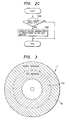
- the CPU in execution of the routine first determines whether the main power supply is on. If it is not, control is returned to the last called routine, and the routine shown in Figure 2B ends. If the main power supply is on, then in a step S2 it is detected whether the disk is set in a reproducing position. If it is not, it is determined that the disk has not been loaded yet (i.e., there has been no power interruption, and this is a true initialization), and so a disk loading step is performed in step S8. If the disk is in the reproducing position, then it is determined that there has been a turning off of the main power supply during a reproducing operation of the disk (i.e., a power interruption). Thus, a power supply resetting flag is set in a step S3.
- a step S4 the video information stored in the video memory 18 is read repeatedly, the selection switch 15 in Figure 1B being set to the side b to enable this.
- the video memory 18 will contain a field of information, and thus will be able to output a still picture in accordance with the operation of the backup power supply even if the main power supply is off, so long as the final readout video information has been stored, unless the disk has been ejected in the meantime.
- the CPU returns the pickup to a home position (step S5). It should be noted that at the time of power interruption, the pickup would have been at a readout position immediately before power interruption.
- the routine cycles through the step S6 until the pickup is returned to the home position.
- step S7 the pickup is returned to the home position, it is sent to the most internal position on the disk containing video information.
- This position may be the most internal overall position on the disk if a video disk is being played, or simply may be the most internal position of the region 1b.
- This step is carried out whether or not the disk was in the reproducing position at step S2.
- the CPU reads a table of contents (step S9) which is contained at that track, once the pickup has been focused on that track. This information indicates contents of respective regions on the disk surface.
- step S10 it is detected whether the repeated power supply on flag has been set or not. Note that this flag will be set if the disk had been set to the reproducing position, but would not have been set if the disk was not at the reproducing position at step S2. If the flag has been set, the last address prior to power interruption is searched (step S11). Otherwise the playing operation is merely started in step S12.
- step S13 If the reproducing operation has not ended (step S13), the playing operation in step S12 is continued. Once reproduction has ended, the pickup is sent to the home position (step S14), and the disk is ejected (step S15). When it is detected that the disk has been ejected, the video memory 18 and power supply repeated on flag are reset (step S16), thus ending the series of operations shown in Figure 2B.
- step S20 it is detected in step S20 whether the main power supply is off. If it is not, the most recent address identifying the position on the disk from which video information was recorded in the memory 18 is transferred to memory in step S21. More specifically, when it is determined that there is a main power supply failure by detecting a power switch off condition while a playing operation is being carried out, the CPU transfers frame number data as an address which indicates the position at which the most recent read out video information has been recorded to a predetermined address in the address memory. In this manner, the frame number of the most recent video information is written into the address memory.
- the most recent video information reproduced immediately before the power interruption is stored in a video memory, and may be repeatedly output to a television monitor during rise time which occurs during the reinitialization of the disk player.
- the reproducing operation also can be restarted from the last known point before the interruption.
- reproduction of the noise can be prevented during the rise period which is relatively long for video players because disk rotational speed is higher for a video disk than for an audio CD disk.
Landscapes
- Engineering & Computer Science (AREA)
- Multimedia (AREA)
- Signal Processing (AREA)
- Television Signal Processing For Recording (AREA)
- Signal Processing For Digital Recording And Reproducing (AREA)
- Optical Recording Or Reproduction (AREA)
Claims (16)
- Plattenspieler, der Bildinformation wiedergibt, die auf einer Informationsaufzeichnungsplatte gespeichert ist, wobei der Plattenspieler eine Einrichtung (21) zum Empfang eines Befehls zur Auslösung eines Suchvorgangs während der Wiedergabe der Bildinformation von der Informationsaufzeichnungsplatte; eine Einrichtung (21), die, wenn der Suchvorgang ausgelöst worden ist, ermittelt, ob ein Feld der Bildinformation in einem Bildspeicher (18) des Plattenspielers gespeichert worden ist; und eine Einrichtung (19) zum wiederholten Auslesen des Feldes der Bildinformation, das im Bildspeicher (18) gespeichert worden ist, bis der Suchvorgang abgeschlossen ist, vorausgesetzt, das Feld der Bildinformation ist im Bildspeicher (18) gespeichert worden, umfaßt.
- Plattenspieler nach Anspruch 1, zur Anwendung mit einer Informationsaufzeichnungsplatte, die einen ersten Bereich (1a) zur Speicherung von Toninformation und einen zweiten Bereich (1b) zur Speicherung von Bildinformation umfaßt, und weiterhin eine Einrichtung (5, 6, 37) zur Bewegung einer Abtasteinrichtung (3) des Plattenspielers zwischen dem ersten und dem zweiten Bereich enthält, wobei die Leseeinrichtung das Feld der Bildinformation während der Bewegung der Abtasteinrichtung wiederholt ausliest.
- Plattenspieler nach Anspruch 1 oder Anspruch 2, wobei, wenn kein Feld der Bildinformation im Bildspeicher gespeichert worden ist, die Leseeinrichtung andere, zuvor in den Speicher geschriebene Bildinformation während der Initialisierung des Plattenspielers ausliest.
- Plattenspieler nach Anspruch 3, wobei die andere Bildinformation Blaubild-Information umfaßt.
- Plattenspieler nach Anspruch 3, wobei die Leseeinrichtung die andere Bildinformation mit einem Bilderzeuger erzeugt.
- Plattenspieler zu Wiedergabe von auf einer Informationsaufzeichnungsplatte gespeicherter Bildinformation, wobei der Plattenspieler einen Bildspeicher (18) zu Speicherung wenigstens eines Feldes von Bildinformation; eine Hauptstromversorgung; eine Reservestromversorgung, die dem Bildspeicher Strom zuführt, wenn die Hauptstromversorgung unterbrochen ist; eine Einrichtung (19) zur Speicherung eines aktuellsten Feldes von Bildinformation im Bildspeicher während eines Wiedergabevorgangs, bei dem der Plattenspieler die Bildinformation von der Informationsaufzeichnungsplatte wiedergibt; und eine Einrichtung (19, 21) zum wiederholten Lesen des Feldes der im Bildspeicher gespeicherten Bildinformation während eines "Aus"-Zustandes der Hauptstromversorgung und zum wiederholten Lesen des Feldes der Bildinformation auch nach der Feststellung eines "Ein"-Zustandes der Haupstromversorgung während der Wiederinitialisierung des Plattenspielers bis zum Abschluß der Wiederinitialisierung, umfaßt.
- Plattenspieler nach Anspruch 6, zur Anwendung mit einer Informationsaufzeichnungsplatte, die eine kombinierte Platte zur Speicherung von Toninformation in einem ersten Bereich (1a) davon und von Bildinformation in einem zweiten Bereich (1b) davon umfaßt, wobei der Plattenspieler weiterhin eine Einrichtung (21) enthält, die eine aktuellste Adresse speichert, die für eine Position einer Abtasteinrichtung der Platte steht; sowie eine Einrichtung zur Rückführung der Abtasteinrichtung zu der Position nach der Wiederinitialisierung des Plattenspielers.
- Verfahren zum Betrieb eines Plattenspielers, der Bildinformation wiedergibt, die auf einer Informationsaufzeichnungsplatte gespeichert ist, wobei das Verfahren die folgenden Schritte umfaßt:
Erzeugung eines Befehls zur Auslösung eines Suchvorgangs während der Wiedergabe der Bildinformation von der Informationsaufzeichungsplatte;
Ermittlung, ob ein Feld der Bildinformation in einem Bildspeicher (18) des Plattenspielers gespeichert worden ist, wenn der Suchvorgang ausgelöst worden ist; und
wiederholtes Auslesen des Feldes der Bildinformation bis der Suchvorgang abgeschlossen ist, wenn ein Feld der Bildinformation im Bildspeicher gespeichert worden ist. - Verfahren nach Anspruch 8, wobei die Informationsaufzeichnungsplatte einen ersten Bereich (1a) zur Speicherung von Toninformation und einen zweiten Bereich (1b) zur Speicherung von Bildinformation umfaßt, wobei das Verfahren weiterhin den Schritt der Bewegung einer Abtasteinrichtung (3) des Plattenspielers zwischen dem ersten und dem zweiten Bereich enthält, wobei der Schritt des Auslesens des Feldes der Bildinformation während der Bewegung der Abtasteinrichtung wiederholt ausgeführt wird.
- Verfahren nach Anspruch 8 oder Anspruch 9, wobei, wenn kein Feld der Bildinformation im Bildspeicher gespeichert worden ist, das Verfahren den Schritt des Auslesens anderer Bildinformation während der Initialisierung des Plattenspielers umfaßt, die zuvor in den Speicher geschrieben wurde.
- Verfahren nach Anspruch 10, wobei die andere Bildinformation Blaubild-Information umfaßt.
- Verfahren nach Anspruch 10, wobei der Schritt des Auslesen der anderen Bildinformation den Schritt der Erzeugung der anderen Bildinformation mit einem Bilderzeuger umfaßt.
- Verfahren zum Betrieb eines Plattenspielers zur Wiedergabe von auf einer Informationsaufzeichnungsplatte gespeicherter Bildinformation, wobei der Plattenspieler einen Bildspeicher (18) zu Speicherung wenigstens eines Feldes von Bildinformation; eine Hauptstromversorgung; eine Reservestromversorgung, die dem Bildspeicher Strom zuführt, wenn die Hauptstromversorgung unterbrochen ist, umfaßt, wobei das Verfahren die Speicherung eines aktuellsten Feldes von Bildinformation im Bildspeicher während eines Wiedergabevorgangs, bei dem der Plattenspieler die Bildinformation von der Informationsaufzeichnungsplatte wiedergibt, umfaßt; sowie das wiederholte Lesen des Feldes der im Bildspeicher gespeicherten Bildinformation während eines "Aus"-Zustandes der Hauptstromversorgung, den Schritt des wiederholten Lesens des Feldes der Videoinformation, der auch nach der Feststellung eines "Ein"-Zustandes der Haupstromversorgung, während der Wiederinitialisierung des Plattenspielers bis zum Abschluß der Wiederinitialisierung ausgeführt wird.
- Verfahren nach Anspruch 13, wobei die Informationsaufzeichnungsplatte eine Platte umfaßt, auf der nur Bildinformation gespeichert ist.
- Verfahren nach Anspruch 13, wobei die Informationsaufzeichnungsplatte eine kombinierte Platte zur Speicherung von Toninformation in einem ersten Bereich (1a) davon und von Bildinformation in einem zweiten Bereich (1b) davon umfaßt.
- Verfahren nach Anspruch 15, wobei der Speicherschritt den Schritt der Speicherung einer aktuellsten Adressen einschließt, die für eine Position einer Abtasteinrichtung der Platte unmittelbar vor der Feststellung des "Aus"-Zustandes steht; wobei das Verfahren weiterhin den Schritt der Rückführung der Abtasteinrichtung zu der Position nach der Wiederinitialisierung des Plattenspielers umfaßt.
Applications Claiming Priority (4)
| Application Number | Priority Date | Filing Date | Title |
|---|---|---|---|
| JP300548/86 | 1986-12-16 | ||
| JP30054886A JPS63152079A (ja) | 1986-12-16 | 1986-12-16 | デイスク再生装置におけるサ−チ方法 |
| JP300504/86 | 1986-12-17 | ||
| JP61300504A JPS63152291A (ja) | 1986-12-17 | 1986-12-17 | デイスク再生装置における最終画面再生方法 |
Publications (3)
| Publication Number | Publication Date |
|---|---|
| EP0274255A2 EP0274255A2 (de) | 1988-07-13 |
| EP0274255A3 EP0274255A3 (en) | 1989-07-19 |
| EP0274255B1 true EP0274255B1 (de) | 1993-02-24 |
Family
ID=26562355
Family Applications (1)
| Application Number | Title | Priority Date | Filing Date |
|---|---|---|---|
| EP87311064A Revoked EP0274255B1 (de) | 1986-12-16 | 1987-12-16 | Vorrichtung zum Abspielen einer Videoplatte und Verfahren zum Wiedergeben der Videoinformation |
Country Status (3)
| Country | Link |
|---|---|
| US (1) | US4872067A (de) |
| EP (1) | EP0274255B1 (de) |
| DE (1) | DE3784333T2 (de) |
Families Citing this family (14)
| Publication number | Priority date | Publication date | Assignee | Title |
|---|---|---|---|---|
| EP0289914B1 (de) * | 1987-05-07 | 1993-10-27 | Pioneer Electronic Corporation | Verfahren zum Aufnehmen und Wiedergeben von Information auf und von einer Aufnahmeplatte |
| US5065252A (en) * | 1988-02-29 | 1991-11-12 | Pioneer Electronic Corporation | Method and apparatus for recording and reproducing picture information enabling the mixing of images of a video format signal and graphic codes recorded on a single recording medium |
| JPH01273275A (ja) * | 1988-04-25 | 1989-11-01 | Pioneer Electron Corp | 画像情報の記録再生方式 |
| JPH01273270A (ja) * | 1988-04-25 | 1989-11-01 | Pioneer Electron Corp | 記録媒体の演奏装置における演奏方式及び情報記録再生方式 |
| JPH02104193A (ja) * | 1988-10-13 | 1990-04-17 | Pioneer Electron Corp | 映像再生装置 |
| EP0402135A3 (de) * | 1989-06-08 | 1992-09-09 | Kabushiki Kaisha Toshiba | Bildwiedergabevorrichtung und -verfahren |
| KR940000461B1 (ko) * | 1989-12-15 | 1994-01-21 | 주식회사 금성사 | Tv수상기의 화면 정지회로 |
| SG50668A1 (en) * | 1990-10-01 | 1998-07-20 | Sony Corp | Disc reproducing apparatus |
| JP3396894B2 (ja) * | 1992-05-14 | 2003-04-14 | ソニー株式会社 | 音響再生装置 |
| JPH08214265A (ja) | 1995-01-31 | 1996-08-20 | Sony Corp | 符号化データの再生方法および再生装置 |
| JPH10508138A (ja) * | 1995-08-22 | 1998-08-04 | フィリップス エレクトロニクス ネムローゼ フェンノートシャップ | 媒体のオーディオ信号及び/又はビデオ信号読取り用プレーヤ |
| KR100283948B1 (ko) * | 1997-09-12 | 2001-05-02 | 윤종용 | 디스크플레이어제어장치및그방법 |
| US6393201B1 (en) * | 1998-01-07 | 2002-05-21 | Hitachi, Ltd. | Reproducing apparatus and reproducing/recording apparatus memorizing identification information of optical information meda and method thereof |
| CN100361521C (zh) * | 1999-11-10 | 2008-01-09 | 汤姆森特许公司 | 在可记录媒体上识别和跳越视频信号的片段的方法和设备 |
Family Cites Families (8)
| Publication number | Priority date | Publication date | Assignee | Title |
|---|---|---|---|---|
| FR1354910A (fr) * | 1963-01-24 | 1964-03-13 | Teverama Sa | Procédé d'enregistrement et de reproduction d'images cinématographiques et support d'un tel enregistrement |
| DE2645747C2 (de) * | 1976-10-09 | 1984-02-16 | Robert Bosch Gmbh, 7000 Stuttgart | Verfahren zur Wiedergabe von einzelnen Bildern von auf bandförmigen Trägern aufgezeichneten Fernsehsignalen |
| JPS5558868A (en) * | 1978-10-21 | 1980-05-01 | Takeshi Harada | Video reproducing unit |
| JPS5730476A (en) * | 1980-07-29 | 1982-02-18 | Pioneer Video Corp | Recording and reproduction system for video disk |
| JPS57148975U (de) * | 1981-03-12 | 1982-09-18 | ||
| US4602295A (en) * | 1982-10-23 | 1986-07-22 | Pioneer Electronic Corporation | Recording and reproducing method for video format signal |
| JPH0634305B2 (ja) * | 1983-03-04 | 1994-05-02 | ソニー株式会社 | デイジタルデイスクによるデ−タ伝送システム |
| US4558375A (en) * | 1983-04-27 | 1985-12-10 | Sontheimer Carl Gustav | Method and apparatus for recording and retrieving video information in two modes on a single laser recording disc |
-
1987
- 1987-12-16 EP EP87311064A patent/EP0274255B1/de not_active Revoked
- 1987-12-16 DE DE8787311064T patent/DE3784333T2/de not_active Revoked
- 1987-12-16 US US07/133,836 patent/US4872067A/en not_active Expired - Fee Related
Also Published As
| Publication number | Publication date |
|---|---|
| US4872067A (en) | 1989-10-03 |
| DE3784333T2 (de) | 1993-07-15 |
| EP0274255A2 (de) | 1988-07-13 |
| DE3784333D1 (de) | 1993-04-01 |
| EP0274255A3 (en) | 1989-07-19 |
Similar Documents
| Publication | Publication Date | Title |
|---|---|---|
| US4872068A (en) | Disk playing method resulting in reduced start-up time | |
| US4885644A (en) | Spindle servo device for data recording disk reproducing apparatus | |
| EP0274255B1 (de) | Vorrichtung zum Abspielen einer Videoplatte und Verfahren zum Wiedergeben der Videoinformation | |
| US4878129A (en) | Method for reproduction of stored video signals with disk reproducing apparatus | |
| EP0270215B1 (de) | Verfahren und Gerät zur Wiedergabe von optischen Platten sowohl mit Ton- als auch mit Ton- und Bildinformationen | |
| US4845572A (en) | Multiplied-speed reproducing system in information reproducing apparatus | |
| US5191567A (en) | Method for playback of a portion of a recorded disk played before interruption of playback | |
| JPH0422296B2 (de) | ||
| KR100427528B1 (ko) | 디스크 재생 시스템 | |
| JPH0373067B2 (de) | ||
| JPS63152291A (ja) | デイスク再生装置における最終画面再生方法 | |
| EP0272139B1 (de) | Wiedergabeverfahren für einen Plattenspieler | |
| KR960003704B1 (ko) | 디스크재생시스템의 고속기동장치와 그 방법 | |
| US4794466A (en) | Disk player | |
| JP2551571B2 (ja) | 情報記録ディスク再生装置 | |
| JPS63152079A (ja) | デイスク再生装置におけるサ−チ方法 | |
| JPS63155461A (ja) | デイスク再生装置における再生方法 | |
| JP2612693B2 (ja) | デイスク再生装置におけるビデオ信号処理装置 | |
| JPH01178167A (ja) | 複合ディスク及びその演奏方法 | |
| JPS63220471A (ja) | 複合デイスク演奏装置における記録再生方法 | |
| JPS63268179A (ja) | ディスク記録情報再生装置における再開画像再生方法 | |
| JPS63316682A (ja) | スピンドルモ−タの停止制御装置 | |
| JPS63282981A (ja) | ディスク演奏方法 | |
| JPH0773362B2 (ja) | ビデオディスクの再生方法 | |
| JPS6353776A (ja) | 情報再生信号装置におけるサ−チ方式 |
Legal Events
| Date | Code | Title | Description |
|---|---|---|---|
| PUAI | Public reference made under article 153(3) epc to a published international application that has entered the european phase |
Free format text: ORIGINAL CODE: 0009012 |
|
| AK | Designated contracting states |
Kind code of ref document: A2 Designated state(s): DE FR GB |
|
| PUAL | Search report despatched |
Free format text: ORIGINAL CODE: 0009013 |
|
| AK | Designated contracting states |
Kind code of ref document: A3 Designated state(s): DE FR GB |
|
| 17P | Request for examination filed |
Effective date: 19900110 |
|
| 17Q | First examination report despatched |
Effective date: 19911205 |
|
| GRAA | (expected) grant |
Free format text: ORIGINAL CODE: 0009210 |
|
| AK | Designated contracting states |
Kind code of ref document: B1 Designated state(s): DE FR GB |
|
| REF | Corresponds to: |
Ref document number: 3784333 Country of ref document: DE Date of ref document: 19930401 |
|
| ET | Fr: translation filed | ||
| PLBI | Opposition filed |
Free format text: ORIGINAL CODE: 0009260 |
|
| 26 | Opposition filed |
Opponent name: INTERESSENGEMEINSCHAFT FUER RUNDFUNKSCHUTZRECHTE E Effective date: 19931124 |
|
| PGFP | Annual fee paid to national office [announced via postgrant information from national office to epo] |
Ref country code: GB Payment date: 19941206 Year of fee payment: 8 |
|
| PGFP | Annual fee paid to national office [announced via postgrant information from national office to epo] |
Ref country code: DE Payment date: 19941208 Year of fee payment: 8 |
|
| PGFP | Annual fee paid to national office [announced via postgrant information from national office to epo] |
Ref country code: FR Payment date: 19941209 Year of fee payment: 8 |
|
| RDAG | Patent revoked |
Free format text: ORIGINAL CODE: 0009271 |
|
| STAA | Information on the status of an ep patent application or granted ep patent |
Free format text: STATUS: PATENT REVOKED |
|
| 27W | Patent revoked |
Effective date: 19950101 |
|
| GBPR | Gb: patent revoked under art. 102 of the ep convention designating the uk as contracting state |
Free format text: 950101 |