EP0274544A1 - Bandkassette - Google Patents
Bandkassette Download PDFInfo
- Publication number
- EP0274544A1 EP0274544A1 EP87904733A EP87904733A EP0274544A1 EP 0274544 A1 EP0274544 A1 EP 0274544A1 EP 87904733 A EP87904733 A EP 87904733A EP 87904733 A EP87904733 A EP 87904733A EP 0274544 A1 EP0274544 A1 EP 0274544A1
- Authority
- EP
- European Patent Office
- Prior art keywords
- cassette
- tape
- cassette body
- magnetic tape
- error
- Prior art date
- Legal status (The legal status is an assumption and is not a legal conclusion. Google has not performed a legal analysis and makes no representation as to the accuracy of the status listed.)
- Granted
Links
Images








Classifications
-
- G—PHYSICS
- G11—INFORMATION STORAGE
- G11B—INFORMATION STORAGE BASED ON RELATIVE MOVEMENT BETWEEN RECORD CARRIER AND TRANSDUCER
- G11B25/00—Apparatus characterised by the shape of record carrier employed but not specific to the method of recording or reproducing, e.g. dictating apparatus; Combinations of such apparatus
- G11B25/06—Apparatus characterised by the shape of record carrier employed but not specific to the method of recording or reproducing, e.g. dictating apparatus; Combinations of such apparatus using web-form record carriers, e.g. tape
- G11B25/066—Apparatus characterised by the shape of record carrier employed but not specific to the method of recording or reproducing, e.g. dictating apparatus; Combinations of such apparatus using web-form record carriers, e.g. tape adapted for use with containers of different sizes or configurations; adaptor devices therefor
-
- G—PHYSICS
- G11—INFORMATION STORAGE
- G11B—INFORMATION STORAGE BASED ON RELATIVE MOVEMENT BETWEEN RECORD CARRIER AND TRANSDUCER
- G11B23/00—Record carriers not specific to the method of recording or reproducing; Accessories, e.g. containers, specially adapted for co-operation with the recording or reproducing apparatus ; Intermediate mediums; Apparatus or processes specially adapted for their manufacture
- G11B23/02—Containers; Storing means both adapted to cooperate with the recording or reproducing means
- G11B23/04—Magazines; Cassettes for webs or filaments
- G11B23/08—Magazines; Cassettes for webs or filaments for housing webs or filaments having two distinct ends
- G11B23/087—Magazines; Cassettes for webs or filaments for housing webs or filaments having two distinct ends using two different reels or cores
-
- G—PHYSICS
- G11—INFORMATION STORAGE
- G11B—INFORMATION STORAGE BASED ON RELATIVE MOVEMENT BETWEEN RECORD CARRIER AND TRANSDUCER
- G11B23/00—Record carriers not specific to the method of recording or reproducing; Accessories, e.g. containers, specially adapted for co-operation with the recording or reproducing apparatus ; Intermediate mediums; Apparatus or processes specially adapted for their manufacture
- G11B23/02—Containers; Storing means both adapted to cooperate with the recording or reproducing means
- G11B23/04—Magazines; Cassettes for webs or filaments
- G11B23/08—Magazines; Cassettes for webs or filaments for housing webs or filaments having two distinct ends
- G11B23/087—Magazines; Cassettes for webs or filaments for housing webs or filaments having two distinct ends using two different reels or cores
- G11B23/08707—Details
- G11B23/08735—Covers
Definitions
- the present invention relates to a tape cassette employed, for example, for video tape recorders (which will hereinafter be referred to as VTR) and so on, and more particularly to such a tape cassette suitable for VTRs which allows loading of tape cassettes of two, large and small, classes (kinds) whose dimensions and mechanisms are respectively different from each other.
- VTR video tape recorders
- VTRs Conventional hitherto as such a VTR system are 3/4-inch VTRs and VHSVTRs and, in 3/4-inch VTRs, in order to allow use of two, large and small, classes cassettes, each of cassettes is arranged to have guide channels so as to be guided to a predetermined position in a cassette garage.
- VHSVTR cassettes an adapter is attached to a smaller cassette so as to be used similarly to a larger cassette and the smaller cassette is guided to a predetermined position in a cassette garage.
- FIG. 18 A structure of a VTR is illustrated in Fig. 18, in which numeral 1 represents a tape-cassette garage (which will hereinafter be referred to as cassette garage) for guiding insertion of a cassette.
- the cassette garage 1 has a frontage 2 whose dimension is slightly greater in length and height than that of the larger cassette and is provided with a pair of holes 3 and a projection 4 at its bottom surface la and equipped with a pair of cut-and-raised portion 5 at the front edge of its bottom surface la.
- the cassette garage 1 is arranged to be movable upwardly and downwardly by means of a sliding mechanism, not shown.
- a pair of reel bases 7 which are fixed on a bedplate 6 and which are rotated by means of a motor, not shown, so that the reel bases 7 are fitted in the holes 3 in response to downward movement of the cassette garage 1.
- Fig. 19 is an illustration of a structure of a large cassette 8.
- the body 9 of the large cassette 8 is made up by engagement and fastening of an upper case 9a and a lower case 9b and encases a pair of tape reels 10.
- an opening portion 11 At the front face of the cassette body 8 is defined an opening portion 11 and along the opening portion 11 is stretched a magnetic tape (not shown) wound around the tape reels 10.
- Numeral 12 is an opened and closed cover provided rotatably with respect to the case body 9 for covering from the outside the magnetic tape (not shown) stretched along the opening portion 11.
- a recess 13 for prevention of a reverse-insertion and, when as shown in Fig.
- Fig. 21 shows a structure of a small cassette 16.
- the body 17 of the small cassette 16 is made up with engagement and fastening of an upper case 17a and a lower case 17b each other and encases a pair of tape reels 18, 19.
- teeth 20 On the periphery of a lower flange 19a of the tape reel 19 are formed teeth 20 which are exposed from a side surface of the cassette body 17.
- Numeral 21 is an opened and closed cover provided on the case body 17 for covering a magentic tape (not shown) wound around the tape reels 18 and 19 from the front side.
- Fig. 22 illustrates the structure of a cassette adapter 22, whose outer dimension is equal to that of the large cassette 8, for encasing the small cassette 16.
- the cassette adapter 22 has the same outer dimension as the large cassette 8 and, at the left side, has a space 23 for encasing the small cassette 16.
- arms 25 each of which has a guide roller 24 planted at one end portion thereof for stretching the magentic tape (not shown) wound around the reels 18, 19 up to the same postion as in the case of the large cassette.
- Numeral 26 depicts a guide channel.
- Numeral 27 represents an opened and closed cover for holding the inserted small cassette 16 by depression from the upper side, the arms 25 being automatically operated in response to closing of the opened and closed cover 27.
- a rotatable first rotating body 28 whose configuration is substantially similar to that of the reel 10 of the large cassette 8.
- teeth On the periphery of a flange 28a of the first rotating body 28 are formed teeth (not shown) which is in turn engaged with second and third rotating bodies 29 and 30 which have respectively teeth similar to that of the first rotating body 28 and which are arranged rotatably, the third rotating body 30 being exposed into the space 23.
- Numeral 31 is an opened and closed cover provided so as to cover the stretched magnetic tape (not shown) from the front side, and at a substantial center portion of the opened and closed cover 31 is provided a recess 32 for prevention of error-insertion.
- Numeral 33 is a safety lug.
- Fig. 23 a description of the case of initially mounting the large cassette 8 will be made with reference to Fig. 23.
- the large cassette 8 is moved in a direction indicated by an arrow with the opened and closed cover 12 being advanced and, in response to reaching the inside of the frontage 2, is guided and inserted by means of the engagement of the guide channel 14 with both side surfaces lb, lc and projection 4 of the cassette garage 1. Termination of the insertion thereof into the cassette garage 1 is made by coming into contact with the cut-and-raised portions 5. Thereafter, the entire cassette garage 1 is moved downwardly whereby the reel bases 7 are inserted into the holes 3 to be engaged with the reels 10, resulting in the recording and reproducing state.
- a description of the case of mounting the small cassette 16 will be made with reference to Fig. 24.
- the description of the process after the mounting on the cassette garage 1 will be omitted because it is the same as in the case of the mounting of the large cassette 8.
- the opened and closed cover 21 of the small cassette 16 is first full-opened and then encased in the reception space 23 of the cassette adapter 22 so that the opened and closed cover 21 of the small cassette 16 and the opened and closed cover 12 of the cassette adapter 22 are directed to same direction.
- the opened and closed cover 27 of the adapter 22 is set to the closed state.
- an exclusive use adapter is required for use of the small cassette and the provision of the adapter results in cost-increase and further results in being troublesome in operation.
- the structure of the small cassette itself results in poor airtightness because it is required that a portion of teeth is exposed due to the relation between the adapter and drive means, and the poor tightness allows insertion of dust therefrom and causes increase of drop out, deterioration of the image quality and so on. Therefore, the above-mentioned large and small cassette system is not in a sufficient result.
- the present invention contemplates to provide a tape cassette suitable for large and small casette systems in which the mounting on the same VTR can be performed without provision of the adapter, the upside-down insertion can be obviated and an excellent airtightness is provided for the small cassette.
- An arrangement of the present invention comprises a cassette body constructed of upper and lower cases for encasing a pair of reels aroung which a magentic tape is wound, a front cover for covering the magnetic tape stretched in the front of the cassette body and a rear cover for covering the rear side of the magnetic tape and the front edge of the upper surface of the rear cover is arranged to be normal to the upper surface of the cassette body, thereby allowing prevention of error-insertion, simple and sure mounting on VTR or the like, provision of excellent airtightness, and deterioration of image quality due to increase of drop out caused by entering of dust and so on.
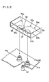
- Figs. 1 and 2 are perspective view showing one example of VTRs used for the present invention
- Fig. 3 is a perspective view illustrating an embodiment of large cassettes
- Fig. 4 is an exploded perspective view showing a structure of a safety lug of the large cassette
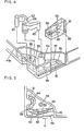
- Fig. 5 is a plane view for describing operation of the safety lug of the large cassette
- Fig. 6 is a perspective view showing the principal portion of the safety lug structure
- Fig. 7 is a perspective view showing another safety lug structure of the large cassette
- Fig. 8 is a plane view of the main portion showing an operating diagram when an automatic changing device of the small cassette is used
- Fig. 9 is a cross-sectional view of the main portion
- Fig. 1 and 2 are perspective view showing one example of VTRs used for the present invention
- Fig. 3 is a perspective view illustrating an embodiment of large cassettes
- Fig. 4 is an exploded perspective view showing a structure of a safety lug of the large cassette
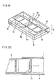
- FIG. 10 is a perspective view showing an embodiment of the small cassette
- Fig. 11 is a cross-sectional view of the front main portion of the small cassette
- Fig. 12 is a cross-sectional view of the main portion for describing inserting operation of the small cassette
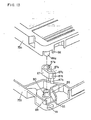
- Fig. 13 is an exploded perspective view showing a structure of prevention of error-erase of the small cassette
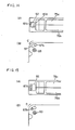
- Figs. 14A and 15A are plane views for describing operation of the error-erase prevention of the small cassette
- Figs. 14B and 15B are bottom views thereof
- Figs. 16 is a perspective view showing mounting operation of the large cassette on a VTR
- Fig. 17 is a perspective view showing a mounting operation of the small cassette on VTR
- Fig. 16 is a perspective view showing mounting operation of the large cassette on a VTR
- Fig. 17 is a perspective view showing a mounting operation of the small cassette on VTR
- Fig. 16 is a perspective view showing mounting operation of the large cassette on a VTR
- FIG. 18 is a perspective view of a VTR for showing a conventional one
- Fig. 19 is a perspective view showing a large cassette therein
- Fig. 20 is a cross-sectional view of the main portion for operation of the large cassette
- Fig. 21 is a perspective view of a small cassette therein
- Fig. 22 is a perspective view of an adapter therein
- Fig. 23 is a perspective view showing mounting operation of the large cassette on a VTR
- Fig. 24 is a perspective view showing mounting operation of the small cassette on the VTR.
- numeral 34 represents a cassette garage for guiding insertion of a cassette and the cassette garage 34 has a frontage 35, whose dimention is slightly greater in longitudinal length and height than that of a larger cassette, and further has a pair of holes 36a and 36b and a hole 37 on its bottom surface, the hole 37 being positioned between the pair of holes 36a abd 36b and having a diameter slightly smaller than that of the pair of holes 36a and 36b.
- a projection 38 is provided between the holes 36a and 37.
- cut-and-raised portions 39a, 39b and 39c are provided on the front edge of the bottom surface 34a.
- a micro switch (not shown) which is arranged to be operatively associated with an up-and-down moving mechanism of a reel base 42 which will be described hereinafter.
- the cassette garage 34 is arranged to be movable upwardly and downwardly by means of a sliding mechanism (not shown).
- a pair of reel bases 41a and 41b sucured on a bedplate 40 and rotated by means of a motor (not shown), and a reel base 42, positioned between the pair of reel bases 41a and 41b and arranged to be movable upwardly and downwardly and rotatable by means of a motor (not shown).
- the holes 36a, 36b and 37 are respectively engaged with the reel bases 41a, 41b and 42.
- Fig. 1 shows a normal state that the reel base 42 has been moved upwardly
- Fig. 2 illustrates the state that the reel base 42 has been moved downwardly.
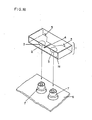
- Fig. 3 is an illustration of a structure of a large cassette 43 used in the embodiment of the present invention.
- the large cassette 43 has a structure substantially similar to that of the large cassette 8 in the above-metnioned conventional example and therefore a description of parts corresponding to those of the large cassette 8 will be omitted and a description will be made in terms of only the different parts therefrom.
- a cassette body 44, an upper case 44a, a lower case 44b, tape reels 45, an opening portion 46, an opened and closed cover 47, a recess 48 and a guide channel 49 respectively correspond to the cassette body 9, upper case 9a, lower case 9b, tape reels 10, opening portion 11, opened and closed cover 12, recess 13 and guide channel 14.
- Numeral 50 represents an error-erase presention portion, the arrangement thereof being as illustrated in Fig. 4.
- numeral 44b is the above-metnioned lower case
- numeral 51 is a channel defined in the error-elimination prevention portion 50
- numeral 52 represents a first recess
- numeral 53 designates a second recess
- numeral 54 depicts screw hole for combination of the upper and lower cases
- numeral 55 represents an error-erase detection hole opened at the lower surface of the lower case 44b
- numeral 56 is a boss, numeral.
- numeral 57 designates an opening portion of the error-elimination prevention portion
- numeral 58 depicts a first part for the error-erase prevention
- numeral-59 is a channel
- numeral 60 is a tongue-like piece for elasticity
- numeral 61 is a hooking portion for operation
- numeral 62 represents an inclined surface
- numeral 63 designates a second part for the error-erase prevention
- numeral 64 is a detection portion
- numeral 65 is a boss
- numeral 66 is a rotation hole.
- the first parts 58 for the error-erase prevention is received in the channel 51 and can be slided along the channel with the hooking portion 61 being engaged with a hook.
- the second parts 63 for-the error-erase prevention is rotatable with the boss 56 being fitted in the rotation hole 66, and the boss 65 is engaged with the channel 59 and the detection portion 64 is fitted in the error-erase detection hole 55 so as to be exposed from the lower surface of the case.
- the boss 65 is moved along this surface and the detection portion 64 is rotated in the direction indicated by an arrow B, whereby the opening portion 57 is present at the error-erase prevention portion and, because of movement of the detection portion 64, an opening portion is also presented at the lower surface side of the case.
- the toungue-like piece 60 for elasticity, for sure positioning, is fitted in the recess 52 when the first parts 58 for error-erase prevention is positioned at the opening portion 57 and fitted in the recess 53 when the opening portion 57 is in the opened state.
- Fig. 6 is an illustration viewed from the lower case.
- Fig. 7 shows another embodiment in which a convexed portion 67 is arranged between the first and second recesses 52 and 53 of the lower case 44b.
- the tongue-like piece 60 should go over the convexed portion 67 when transferred between the first and second recesses 52 and 53 and therefore click feeling can be obtained in response to movement of the first parts 58 for error-erase prevention portion and the first parts 58 is not stopped on the way, thus resulting in sure movement with high reliability.
- the allowance of recording can be judged when the opening becomes absent and the non-allowance of the recording can be decided in response to presence of the opening.
- Numeral 68 represents an automatic changing device and so on provided at both the side surfaces of the cassette body 44 and a gripping portion used at the time of insertion and discharge of thelarge cassette 43.
- the gripping portion 68 comprises gripping rack portions and substantially V-shaped recess 70 and the gripping rack portions are positioned at substantial center portions whereby distinguishing can become easy irrespective of viewing from either upper side or lower side of the large cassette.
- the recess portion 70 is substantially V-shaped, when the cassette body 44 is gripped from the sides having the gripping portions 68, it is possible to surely grip it even if the end configuration of the gripping portion is varied in size as indicated by circles 71 or 72.
- Fig. 10 shows a structure of the small cassette 74 used in the embodiment of the present invnetion.
- a cassette body 75, an upper case 75a, a lower case 75b, tape reels 76, an opening portion 77, an opened and closed cover 78, gripping portions 79, gripping rack portions 79a, and recess portions 79b respectively correspond to the cassette body 44, upper case 44a, lower case 44b, tape reels 45, opening portion 46, opened and closed cover 49, gripping portions 68, gripping rack portions 69 and recess 70.
- Numeral 80 represent a front cover and numeral 81 a rear cover and these structures are illustrated in Fig. 11.
- Fig. 11 is a front side main portion cross-sectional view of the small cassette 74
- the front cover 80 is a cover for covering, from the front side, a magentic tape 82 stretched along the opening portion 77 and is pivotally supported by the case body 75 to be roatable about a shaft 83.
- the rear cover 81 is substantially T-shaped and comprises a top surface portion 81a for covering the magnetic tape 82 from the upside and a rear surface portion 81b for covering it from the rear side and is rotatably pivoted by a rib 84 provided on the front cover 80 and guided slidingly along a guide channel 85 provided in the cassette body 75.
- the magentic tape is sealed for protection from dust by closing the front and rear covers 80 and 81.
- the reverse-insertion prevention recess 13 of the large cassette 8 in the above-mentioned conventional one or the reverse-insertion prevention recess 48 of the large cassette 43 in the above-mentioned embodiment is positioned above the top surface portion 80a of the front cover 80 and hence the recess 13 or 43 cannot be provided on the front cover 80. Therefore, an end portion 81c of the top surface portion 81a of the rear cover 81 is arranged to be a surface which is flat and at right angles to the top surface portion 81a so that, when as shown in Fig.
- NUmeral 86 is an error-erase prevention portion whose structure is arranged as illustrated in Fig. 13. In Fig.
- numeral 75a represents an upper case
- numeral 86a designates an upper case boss
- numeral 87 depicts an error-erase prevention member
- numeral 87a is a cylindrical portion
- numeral 87b is an error-erase detection portion
- numeral 87c is an indication portion
- numeral 87d is a convexed portion for operation
- numeral 87e is concaved portion for positioning
- numeral 75b is a lower case
- numeral 88 is a lower case boss
- numeral 89 is an error-erase prevention piece engaging portion
- numeral 90 is a convexed portion for positioning
- numeral 91 represents an error-erase detection hole.
- the cylindrical portion 87a is fitted in the error-erase prevention member engaging portion 89 of the lower case boss 88 whereby the error-erase prevention member 87 is rotatable thereabout, and the error-erase detection portion 87b is fitted in the error-erase detection hole 91 of the lower case and exposed on the same plane.
- the upper case boss 86a is engaged with the lower case boss 88 after passed through the error-erase prevention member 87 and the upper case 75a is coupled to the lower case 75b by means of a screw 93 shown in Fig. 14.
- Figs. 14 and 15 show the rotationally operated state of the error-erase prevention member 87.
- Fig. 14 in the case that recording is allowed under the condition that the indication portion 87c is protruded from the notch 92, a judgement is made in the deck (not shown) side in that the error-earse detection portion 87b is absent at the error-erase detection hole 91 of the lower surface of the case, resulting in allowance of recording.
- the error-erase prevention member 87 when the error-erase prevention member 87 is rotated in the direction indicated by an arrow C, as shown in Fig. 15, the indication portion 87c is disappeared and decision is made in that the error-erase detection portion 87b is transferred from the error-erase detection hole 91 of the half lower surface up to a position allowed to be detected by the deck side, resulting in inhibition of recording.
- the error-erase prevention member 87 again returns to the original position in response to rotation in the direction indicated by an arrow D and hence the operation can repeatedly made.
- the positioning concaved portions 87e are engaged with the positioning convexed portions 90 and the position of each of the positioning concaved portions 87e provided in two steps corresponds to the state shown in Figs.
- the error-erase prevention member 87 can be rotated with an operating force over a predetremined degree. If the error-erase prevention member 87 is printed so as to be different in color from the cassette body 75, the distinguishing of the member 87 therefrom becomes easier.
- the cut-and-raised portion 39b of them does not come into contact with the small cassette 74 and therefore the micro switch (not shown) provided thereon is not operated so that the reel base 42 is not moved downwardly and is in the same position relation to the reel beases 41a and 41b. Thereafter, the operation is made as well as in the conventional one so that it is driven by means of the reel bases 4la and 41b to be set to the recording or reproducing state.
- a front cover for covering a magnetic tape stretched in the front of a cassette body and a rear cover for covering the rear side of the magentic tape is provided.
- the front edge of the upper surface of the rear cover is formed to be at right angles to the upper surface of the cassette body whereby even in the case that the two kinds of cassettes whose outer dimensions are different from each other are mounted on a VTR, the mounting can be easily and surely achieved without the complex treatments in the conventional one and further excellent airtightness is provided particularly for the small cassette so as to resolve the problem of deteriorating the image quality due to incease of drop out caused by entering of dust and so on, resulting in a great effect.
Landscapes
- Packaging Of Annular Or Rod-Shaped Articles, Wearing Apparel, Cassettes, Or The Like (AREA)
- Automatic Tape Cassette Changers (AREA)
Applications Claiming Priority (8)
| Application Number | Priority Date | Filing Date | Title |
|---|---|---|---|
| JP170121/86 | 1986-07-18 | ||
| JP170123/86 | 1986-07-18 | ||
| JP61170121A JP2604725B2 (ja) | 1986-07-18 | 1986-07-18 | テープカセツト |
| JP61170123A JPH0664890B2 (ja) | 1986-07-18 | 1986-07-18 | テ−プカセツト |
| JP170122/86 | 1986-07-18 | ||
| JP61170122A JPS6326876A (ja) | 1986-07-18 | 1986-07-18 | テ−プカセツト |
| JP300973/86 | 1986-12-17 | ||
| JP61300973A JPH0632192B2 (ja) | 1986-12-17 | 1986-12-17 | テ−プカセツト |
Publications (3)
| Publication Number | Publication Date |
|---|---|
| EP0274544A1 true EP0274544A1 (de) | 1988-07-20 |
| EP0274544A4 EP0274544A4 (de) | 1990-03-21 |
| EP0274544B1 EP0274544B1 (de) | 1993-12-29 |
Family
ID=27474305
Family Applications (1)
| Application Number | Title | Priority Date | Filing Date |
|---|---|---|---|
| EP19870904733 Expired - Lifetime EP0274544B1 (de) | 1986-07-18 | 1987-07-16 | Bandkassette |
Country Status (5)
| Country | Link |
|---|---|
| US (1) | US4844377A (de) |
| EP (1) | EP0274544B1 (de) |
| KR (1) | KR920003643B1 (de) |
| DE (1) | DE3788637T2 (de) |
| WO (1) | WO1988000756A1 (de) |
Cited By (3)
| Publication number | Priority date | Publication date | Assignee | Title |
|---|---|---|---|---|
| EP0341908A3 (en) * | 1988-05-09 | 1990-08-01 | Minnesota Mining And Manufacturing Company | Record/not record latch for recording cassette |
| EP0367454A3 (de) * | 1988-10-31 | 1991-02-27 | Matsushita Electric Industrial Co., Ltd. | Kassettenbehälter für Bandrekorder |
| EP0599718A3 (de) * | 1992-11-25 | 1995-02-15 | Sony Corp | Bandkassetten und Aufzeichnungs- und/oder Wiedergabegerät. |
Families Citing this family (22)
| Publication number | Priority date | Publication date | Assignee | Title |
|---|---|---|---|---|
| NL8802763A (nl) * | 1988-11-10 | 1990-06-01 | Philips Nv | Systeem voor het registreren en/of uitlezen van signalen op informatiedragers in cassettes. |
| US5237470A (en) * | 1988-11-14 | 1993-08-17 | Matsushita Electric Industrial Co., Ltd. | Magnetic tape cassette loading/unloading apparatus which selectively loads different size cassettes |
| US4924039A (en) * | 1989-02-08 | 1990-05-08 | The Hoover Company | Cooled cord reel |
| NL8900805A (nl) * | 1989-04-03 | 1990-11-01 | Philips Nv | Inrichting met een invoeropening van een standaardafmeting. |
| US5873538A (en) * | 1989-04-21 | 1999-02-23 | Tdk Corporation | Magnetic tape cassette |
| EP0400933B1 (de) * | 1989-05-29 | 1995-07-05 | Matsushita Electric Industrial Co., Ltd. | Bandkassette |
| NL8901605A (nl) * | 1989-06-26 | 1991-01-16 | Philips Nv | Systeem voor de opname/weergave van signalen op een magneetband in een cassette. |
| JP2730228B2 (ja) * | 1989-12-06 | 1998-03-25 | ソニー株式会社 | テープカセット |
| JP2770493B2 (ja) * | 1989-11-06 | 1998-07-02 | ソニー株式会社 | テープカセット |
| DE69028288T2 (de) * | 1989-12-27 | 1997-01-09 | Matsushita Electric Ind Co Ltd | Kassettenladegerät |
| US5240200A (en) * | 1990-03-30 | 1993-08-31 | Matsushita Electric Industrial Co., Ltd. | Tape cassette |
| JP2503658Y2 (ja) * | 1990-04-13 | 1996-07-03 | ソニー株式会社 | テ―プカセツト |
| US5240201A (en) * | 1990-05-11 | 1993-08-31 | Paul J. Gelardi | Integrally molded recyclable video tape cassette |
| US5092536A (en) * | 1990-05-11 | 1992-03-03 | Paul J. Gelardi | Integrally molded recyclable video tape cassette |
| US5201476A (en) * | 1990-05-11 | 1993-04-13 | Paul J. Gelardi | Welded video cassette |
| US5114092A (en) * | 1991-01-10 | 1992-05-19 | Paul J. Gelardi | Low cost video cassette |
| AU664536B2 (en) * | 1990-05-11 | 1995-11-23 | Lcv Associates | Integrally molded recyclable video tape cassette |
| US5209426A (en) * | 1990-06-27 | 1993-05-11 | Victor Company Of Japan, Ltd. | Magnetic tape cassette with a plurality of independently movable protective plate members |
| JP3239384B2 (ja) * | 1991-08-27 | 2001-12-17 | ソニー株式会社 | テープカセット |
| US5308015A (en) * | 1992-05-21 | 1994-05-03 | Lcv Associates | Dust door arrangement for video cassettes |
| JP3374486B2 (ja) * | 1993-12-15 | 2003-02-04 | ソニー株式会社 | テープカセット |
| US6031675A (en) * | 1995-08-31 | 2000-02-29 | Sony Corporation | Recording medium device provided with erroneous recording prevention mechanism |
Family Cites Families (14)
| Publication number | Priority date | Publication date | Assignee | Title |
|---|---|---|---|---|
| US3758048A (en) * | 1969-12-23 | 1973-09-11 | Matsushita Electric Industrial Co Ltd | Tape cassette |
| JPS528407Y2 (de) * | 1972-06-29 | 1977-02-22 | ||
| DE2604172B2 (de) * | 1976-02-04 | 1979-05-17 | Dieter 4000 Duesseldorf Grimm | Für Kassettenrekorder vorgesehene Compactcassette |
| JPS5928547Y2 (ja) * | 1978-05-30 | 1984-08-17 | 松下電器産業株式会社 | テ−プカセットの装着装置 |
| GB2098961A (en) * | 1981-05-27 | 1982-12-01 | Matos Don Atilano Fernandez | Prerecorded tape cassettes suitable for use by blind persons |
| JPS5869393U (ja) * | 1981-11-04 | 1983-05-11 | 松下電器産業株式会社 | テ−プカセツト |
| DE3360970D1 (en) * | 1982-05-12 | 1985-11-14 | Hitachi Maxell | Recording tape cartridge |
| JPS5989481U (ja) * | 1982-12-04 | 1984-06-16 | 日立マクセル株式会社 | テ−プカ−トリツジ |
| JPS59168876U (ja) * | 1983-04-22 | 1984-11-12 | 富士写真フイルム株式会社 | 磁気デイスクカ−トリツジ |
| JPS6035377U (ja) * | 1983-08-12 | 1985-03-11 | ソニー株式会社 | テ−プカセツト |
| JPS60185275A (ja) * | 1984-03-05 | 1985-09-20 | Matsushita Electric Ind Co Ltd | 磁気テ−プカセツト |
| JPH0413796Y2 (de) * | 1985-01-07 | 1992-03-30 | ||
| JPS61156077U (de) * | 1985-03-19 | 1986-09-27 | ||
| US4757399A (en) * | 1986-05-21 | 1988-07-12 | Eastman Kodak Company | Flexible cassette for use with a reel periphery driven transport |
-
1987
- 1987-07-16 DE DE87904733T patent/DE3788637T2/de not_active Expired - Lifetime
- 1987-07-16 US US07/178,993 patent/US4844377A/en not_active Expired - Lifetime
- 1987-07-16 EP EP19870904733 patent/EP0274544B1/de not_active Expired - Lifetime
- 1987-07-16 KR KR1019880700282A patent/KR920003643B1/ko not_active Expired
- 1987-07-16 WO PCT/JP1987/000520 patent/WO1988000756A1/ja not_active Ceased
Cited By (6)
| Publication number | Priority date | Publication date | Assignee | Title |
|---|---|---|---|---|
| EP0341908A3 (en) * | 1988-05-09 | 1990-08-01 | Minnesota Mining And Manufacturing Company | Record/not record latch for recording cassette |
| EP0367454A3 (de) * | 1988-10-31 | 1991-02-27 | Matsushita Electric Industrial Co., Ltd. | Kassettenbehälter für Bandrekorder |
| US5101304A (en) * | 1988-10-31 | 1992-03-31 | Matsushita Electric Industrial Co., Ltd. | Cassette holder device capable of preventing erroneous insertion of cassette |
| US5121271A (en) * | 1988-10-31 | 1992-06-09 | Matsushita Electric Industrial Co., Ltd. | Cassette holder device capable of receiving large and small size cassettes |
| EP0599718A3 (de) * | 1992-11-25 | 1995-02-15 | Sony Corp | Bandkassetten und Aufzeichnungs- und/oder Wiedergabegerät. |
| US5506736A (en) * | 1992-11-25 | 1996-04-09 | Sony Corporation | Memory arrangement for tape cassettes used in recording and/or reproduction |
Also Published As
| Publication number | Publication date |
|---|---|
| KR880701949A (ko) | 1988-11-07 |
| EP0274544B1 (de) | 1993-12-29 |
| US4844377A (en) | 1989-07-04 |
| DE3788637D1 (de) | 1994-02-10 |
| DE3788637T2 (de) | 1994-04-28 |
| KR920003643B1 (ko) | 1992-05-06 |
| EP0274544A4 (de) | 1990-03-21 |
| WO1988000756A1 (en) | 1988-01-28 |
Similar Documents
| Publication | Publication Date | Title |
|---|---|---|
| EP0274544B1 (de) | Bandkassette | |
| US4494161A (en) | Tape cassette | |
| KR890000361B1 (ko) | 테이프 카셋트 | |
| US4807077A (en) | Short time recording tape cassette having a larger open space than that of a long time recording tape cassette | |
| EP0438144B1 (de) | Bandkassette | |
| EP0185364B1 (de) | Magnetplattenkassette mit Auslöschverhinderungseinrichtung | |
| EP0078696A1 (de) | Bandkassette | |
| EP0094087A1 (de) | Aufnahmebandkassette | |
| EP0052479A2 (de) | Bandkassette | |
| KR950000317B1 (ko) | 카세트 장착장치 | |
| US4567536A (en) | Adapter for a miniature type tape cassette | |
| US4703384A (en) | Magnetic tape cassette with reel-lock mechanism | |
| US4809113A (en) | Tape cassette with improved cover structure | |
| JP2757531B2 (ja) | テープカセット | |
| EP0169514B1 (de) | Magnetbandkassette mit Spulenbremsmechanismus | |
| US5786966A (en) | Magnetic tape cassette having improved guard panel structure | |
| EP0543159B1 (de) | Bandkassette und magnetische Aufzeichnungs-/Wiedergabevorrichtung | |
| JPS60214488A (ja) | テ−プカセツト | |
| EP1476868B1 (de) | Datenträgerkassette | |
| JPH0329784Y2 (de) | ||
| US5999363A (en) | Cassette housing having cassette stoppers to prevent mis-insertion | |
| KR960010571B1 (ko) | 데이프 카세트 | |
| CN1088895C (zh) | 带盒适配器 | |
| KR910005216Y1 (ko) | 소형 테이프 카세트 | |
| JP3484898B2 (ja) | テープカセット用リール |
Legal Events
| Date | Code | Title | Description |
|---|---|---|---|
| PUAI | Public reference made under article 153(3) epc to a published international application that has entered the european phase |
Free format text: ORIGINAL CODE: 0009012 |
|
| 17P | Request for examination filed |
Effective date: 19880303 |
|
| AK | Designated contracting states |
Kind code of ref document: A1 Designated state(s): DE FR GB |
|
| A4 | Supplementary search report drawn up and despatched |
Effective date: 19900321 |
|
| 17Q | First examination report despatched |
Effective date: 19910723 |
|
| GRAA | (expected) grant |
Free format text: ORIGINAL CODE: 0009210 |
|
| AK | Designated contracting states |
Kind code of ref document: B1 Designated state(s): DE FR GB |
|
| ET | Fr: translation filed | ||
| REF | Corresponds to: |
Ref document number: 3788637 Country of ref document: DE Date of ref document: 19940210 |
|
| RIN2 | Information on inventor provided after grant (corrected) |
Free format text: SHIOMI, YOSHINORI * KAMIYAMA, TOSHIBUMI * NISHIMURA, AKIHIRO * KAWAGISHI, MASAO * SAKUMOTO, HIDEKI * MATSUI, MASAHIKO |
|
| PLBE | No opposition filed within time limit |
Free format text: ORIGINAL CODE: 0009261 |
|
| STAA | Information on the status of an ep patent application or granted ep patent |
Free format text: STATUS: NO OPPOSITION FILED WITHIN TIME LIMIT |
|
| 26N | No opposition filed | ||
| REG | Reference to a national code |
Ref country code: GB Ref legal event code: IF02 |
|
| PGFP | Annual fee paid to national office [announced via postgrant information from national office to epo] |
Ref country code: GB Payment date: 20060712 Year of fee payment: 20 |
|
| PGFP | Annual fee paid to national office [announced via postgrant information from national office to epo] |
Ref country code: DE Payment date: 20060713 Year of fee payment: 20 |
|
| PGFP | Annual fee paid to national office [announced via postgrant information from national office to epo] |
Ref country code: FR Payment date: 20060719 Year of fee payment: 20 |
|
| REG | Reference to a national code |
Ref country code: GB Ref legal event code: PE20 |
|
| PG25 | Lapsed in a contracting state [announced via postgrant information from national office to epo] |
Ref country code: GB Free format text: LAPSE BECAUSE OF EXPIRATION OF PROTECTION Effective date: 20070715 |