EP0274947A2 - Verfahren und Vorrichtung zum Anbringen eines aus Teilchen und Bindemittel bestehenden verstärkten Bodens auf einer Fläche - Google Patents
Verfahren und Vorrichtung zum Anbringen eines aus Teilchen und Bindemittel bestehenden verstärkten Bodens auf einer Fläche Download PDFInfo
- Publication number
- EP0274947A2 EP0274947A2 EP87402838A EP87402838A EP0274947A2 EP 0274947 A2 EP0274947 A2 EP 0274947A2 EP 87402838 A EP87402838 A EP 87402838A EP 87402838 A EP87402838 A EP 87402838A EP 0274947 A2 EP0274947 A2 EP 0274947A2
- Authority
- EP
- European Patent Office
- Prior art keywords
- binder
- rotor
- treated
- particulate material
- rain
- Prior art date
- Legal status (The legal status is an assumption and is not a legal conclusion. Google has not performed a legal analysis and makes no representation as to the accuracy of the status listed.)
- Granted
Links
Images

Classifications
-
- E—FIXED CONSTRUCTIONS
- E02—HYDRAULIC ENGINEERING; FOUNDATIONS; SOIL SHIFTING
- E02D—FOUNDATIONS; EXCAVATIONS; EMBANKMENTS; UNDERGROUND OR UNDERWATER STRUCTURES
- E02D3/00—Improving or preserving soil or rock, e.g. preserving permafrost soil
- E02D3/005—Soil-conditioning by mixing with fibrous materials, filaments, open mesh or the like
Definitions
- the invention relates to the installation of a particulate material reinforced with a chemical or mechanical binder. More particularly, the invention relates to the treatment of a particulate soil layer in place with a view to strengthening it with a binder.
- the mixing of the various constituents is generally carried out by kneading inside a chamber (or bell) of all the constituents.
- Powdered binders or solid additives are generally spread on the floor to be spread out using a powerful machine with the floor in place to the desired thickness.
- the liquid binders can be injected directly into the mixing chamber which ensures, in all cases, the homogenization of the mixture (cf. GB-A-1 415 524).
- the object of the invention is to remedy the aforementioned drawbacks by proposing a method, as well as a device specially designed for its implementation, making it possible to treat the floors in particular with mechanical binders and to vary the binders introduced in a variable manner.
- the object is achieved in accordance with the invention in that the particulate material is removed from a surface layer of the soils to be treated, in that one immediately projects said material taken in rain falling on the soil to be treated, and in that one introduces the binder into the rain of particulate material.
- the binder can be a liquid, pulverulent or mechanical binder.
- the raining of the particulate material requires its prior spraying according to a particle size which depends on the nature of the soil and the intended use. It is particularly advantageous for the spraying and spraying in the form of rain to be carried out practically simultaneously by spraying means consisting of a horizontal rotor with blades biting into the soil to be treated over the thickness of said surface layer, animated by a general movement of translation forward (substantially perpendicular to the axis of the rotor) and rejecting by projection towards the rear the material taken from said layer.
- the binders are also dispersed, and projected into the rain of particulate material, by pneumatic, hydraulic or mechanical means.
- the introduction and projection means are adapted to water, sprinkle or deliver the product over the entire surface supplied with finely sprayed soil.
- blades can be provided on the rotor; but in general, blades constituted by substantially planar radial blades appear to be the most advantageous. In the case of treatment of loose soil, the system can be supplemented with claws.
- the rotor advantageously cooperates with adjustable elements for confining the jet of material by the rotor: a shield limits the range of the jet, a deflector confines it upwards, while a shoe serves as a springboard for projecting the material.
- a housing is provided above the rotor to avoid returning particles of material towards other organs of the device (in particular on the organs for distributing binders).
- the blade rotor according to the invention can advantageously be integrated into existing soil stabilization machines in place, known under the name of sprayer-mixers, in which a tractor unit drives a rotating mixing rotor, at its engaged lower part. in the ground, in the direction of travel.
- Such machines are marketed, for example, by the companies BOMAG, RAY GO, PETTIBONE, HOES and BROS.
- the mixing rotor is generally equipped with numerous teeth.
- the mixing rotor is replaced by a rotor with blades, and preferably with blades, rotating in the opposite direction to the rotor of the known machine, so as to project the material backwards and upwards, so that it falls back to rain on the ground.
- the blades are continuous across the width of the rotor so as to project the material uniformly.
- the angular speed is variable in order to control the jet of material. It can for example be from 0 to 450 revolutions / min, which, taking into account the diameter of the rotor in an exemplary embodiment, corresponds to tangential blade speeds of the order of 0 to 13 m / s.
- the diameter of the rotor is approximately three times the thickness of the redeposited soil layer (this thickness being for example 15 cm).
- the forward speed is variable, for example between 1.5 and 10 m / min.
- the process and the device of the invention are suitable for conventional binders (a sauce is then sprayed: emulsion, hydraulic binder, organo-mineral binder, chemical binder, resin, etc.), they are very advantageously associated with the projection of 'continuous linear elements according to the teaching of document FR-A-2,572,449 which will be assumed to be known here.
- the injection ramp of the continuous linear elements (wires) is driven by a transverse movement (in the axis of the ramp) and an angular oscillation (along the axis of the ramp) at frequencies close to the hertz, these movements having for object a homogeneous distribution of linear elements in interlocking patterns on the formation surface of the treated layer.
- the continuous linear elements are unwound from coils supported by a creel driven in translation with the entire device.
- the projection ramps for chemical or mechanical binders are arranged either inside and in extension of the shoe, or at the intersection of the shield and the deflector, or even outside the zone delimited by the bottom of the layer, the rotor, deflector and shield.
- the binder can advantageously be prepared before it is sprayed, for example: lime or cement milk, beam or textile roll in a coating bath.
- a vibration compacting device can be associated with the device of the invention.
- an original characteristic of the invention the fact that the material removed falls in rain on the soil to be treated.
- the material falls freely and without hindrance of any kind on the ground, so that the binder can be introduced within this rain and reach the ground itself without being hindered in its path, and therefore end up on the ground in a fully controlled form.
- the entire redeposited layer is thus controlled, whether it is the form of the deposit, its dosage, its homogeneity or its desired heterogeneity (it is possible to choose to deposit a binder only over a given thickness of the redeposited soil layer).
- This free fall in rain implies a transport, a displacement of the soil to be treated, to project said soil away from the sampling and projection organs: this is obtained by a sufficient speed of the rotor and an appropriate adjustment of the adjustable elements for confining the jet.
- a soil sampling rotor which cooperates with a rotor stop to disaggregate the sampled material; this pulverized material then receives a liquid binder; but instead of falling back to rain on the ground, the material passes between the pallets of two rotor-pulverizers intended to shear, crush and even further disaggregate the material in order to ensure the coating of the particles with the conditioned binder, before their redeposition .
- Such a process is incompatible with the aims of the invention: it only makes it possible to ensure a homogeneous distribution of a liquid binder in a particulate material, but no control of this distribution; heterogeneity is not allowed.
- a process is manifestly incompatible with the distribution of a mechanical binder such as a continuous wire, which could not pass freely between the rotor-sprayers.
- FIG. 1 shows a layer of soil 1 (sand, for example), a thickness e of which will be milled by the rotor 2 of axis 3, equipped with blades 4.
- the rotor 2 is rotated about its axis 3 in the direction of the arrow w, and the assembly is driven in translation in the direction of the arrow V, which corresponds to the opposite direction of the peripheral speed of the rotor at the bottom so that the rotor digs the layer 1 and rejects the material taken backwards, forming the jet 5.
- the frame supporting the rotor 2 also supports a deflector 6, a shield 7 and a shoe 8. It also supports an arm 9 on which the projection means 10 of the binder, for example wire 11 coming from a coil 12, are arranged.
- the purpose of the deflector 6 and the shoe 8 is to better channel the sand discharged upwards and backwards by the rotor 2, while the shield 7 limits the range of said jet. It is advantageous that these elements are adjustable, to take into account the quality of the projected sand and the desired layer profiles.
- the spoon blades favor, at low speed of rotation (100 and 200 rpm) shots of sand in a bell, a phenomenon which is accentuated with the increase in the speed of translation V (and therefore with l 'increase in the projected flow) taking into account the greater weight of each sand packet projected with little different kinetic energy.
- a high tendency to segregation is noted for the high rotational speeds (400 rpm), also accentuated by a higher translational speed.
- the deflector 6 cooperates with the shoe 8 to channel the path initial material.
- the blades can be mounted on elastic means so as to partially retract in case a too large stone is caught between the rotor 2 and the shoe 8.
- the sand 5 projected backwards and mixed with the binder from the means 10 falls back onto the ground 1 according to a profile 13 thickening from front to back until forming the complete layer 14.
- the exact shape of the profile 13 is influenced by the positioning of the adjustable means 6,7,8: for example, a more abrupt inclination of the shield 7 results in a more brutal thickening of the profile 13 perpendicular to said shield.
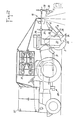
- Figure 2 shows a practical embodiment of the device according to the invention.
- the rotor 2 is attached to the rear of a tractor 20, by means of a lifting frame 21.
- the rotor 2 is housed between two lateral cheeks 22 to which are attached connecting pieces 23 carrying the hinge pin 24 of the shoe 8, the inclination of which is adjustable by means of fixing bars 25 in several positions.
- the lifting frame 21 also supports bars 26, horizontal in the lowered working position, on which are fixed in adjustable manner in translation the deflector support 27 and the shield support 28 7.
- the deflector 6 and the shield 7 are suspended to their respective supports 27,28 by adjustable joints 29,30.
- the wire ejection means 10 are advantageously type which is described in document FR-A-2 572 449, and are supported by the bars 26 of the lifting frame 21.
- the ejected wires come from coils arranged on a creel 31 supported by the towing vehicle 20: taking into account the quantity high wire necessary, it can be provided to install on the vehicle 20 several creels: for example two lateral creels 32 at the front and two lateral creels 31 at the rear.
Landscapes
- Engineering & Computer Science (AREA)
- Structural Engineering (AREA)
- Life Sciences & Earth Sciences (AREA)
- General Life Sciences & Earth Sciences (AREA)
- Soil Sciences (AREA)
- Environmental & Geological Engineering (AREA)
- Agronomy & Crop Science (AREA)
- Mining & Mineral Resources (AREA)
- Paleontology (AREA)
- Civil Engineering (AREA)
- General Engineering & Computer Science (AREA)
- Road Repair (AREA)
- Consolidation Of Soil By Introduction Of Solidifying Substances Into Soil (AREA)
- Floor Finish (AREA)
- Application Of Or Painting With Fluid Materials (AREA)
Priority Applications (1)
| Application Number | Priority Date | Filing Date | Title |
|---|---|---|---|
| AT87402838T ATE66268T1 (de) | 1986-12-15 | 1987-12-23 | Verfahren und vorrichtung zum anbringen eines aus teilchen und bindemittel bestehenden verstaerkten bodens auf einer flaeche. |
Applications Claiming Priority (2)
| Application Number | Priority Date | Filing Date | Title |
|---|---|---|---|
| FR8617514A FR2608183B1 (fr) | 1986-12-15 | 1986-12-15 | Procede et dispositif de mise en place sur une surface d'un sol renforce constitue d'elements particulaires et d'un liant |
| FR8617514 | 1986-12-15 |
Publications (3)
| Publication Number | Publication Date |
|---|---|
| EP0274947A2 true EP0274947A2 (de) | 1988-07-20 |
| EP0274947A3 EP0274947A3 (de) | 1988-07-27 |
| EP0274947B1 EP0274947B1 (en) | 1991-08-14 |
Family
ID=9341895
Family Applications (2)
| Application Number | Title | Priority Date | Filing Date |
|---|---|---|---|
| EP87402838A Expired EP0274947B1 (en) | 1986-12-15 | 1987-12-14 | Method and apparatus for depositing on a surface a reinforced floor composed of particulate matter and a binder |
| EP88900378A Pending EP0294430A1 (de) | 1986-12-15 | 1987-12-14 | Verfahren und vorrichtung zum anbringen eines aus teilchen und bindemittel bestehenden verstärkten bodens auf einer fläche |
Family Applications After (1)
| Application Number | Title | Priority Date | Filing Date |
|---|---|---|---|
| EP88900378A Pending EP0294430A1 (de) | 1986-12-15 | 1987-12-14 | Verfahren und vorrichtung zum anbringen eines aus teilchen und bindemittel bestehenden verstärkten bodens auf einer fläche |
Country Status (5)
| Country | Link |
|---|---|
| EP (2) | EP0274947B1 (de) |
| JP (1) | JPH01501958A (de) |
| AT (1) | ATE66268T1 (de) |
| FR (1) | FR2608183B1 (de) |
| WO (1) | WO1988004709A1 (de) |
Cited By (4)
| Publication number | Priority date | Publication date | Assignee | Title |
|---|---|---|---|---|
| FR2644490A1 (fr) * | 1989-03-15 | 1990-09-21 | Texsol Applic | Procede et machine pour realiser des zones de terrains renforcees, constituees a partir d'un melange d'un materiau granulaire et de fils textiles |
| DE4303285A1 (de) * | 1993-02-05 | 1994-08-11 | Weiss Gmbh & Co Leonhard | Verfahren zur tiefgründigen Bodenverfestigung und Einrichtung zur Durchführung |
| WO1994028248A1 (fr) * | 1993-06-02 | 1994-12-08 | Orgel | Materiaux granuleux pour renforcement de sols et procede d'elaboration |
| FR2727703A1 (fr) * | 1994-12-02 | 1996-06-07 | Orgel | Procede et dispositif de renforcement des sols par des additifs fibreux |
Families Citing this family (4)
| Publication number | Priority date | Publication date | Assignee | Title |
|---|---|---|---|---|
| FR2662193B1 (fr) * | 1990-05-21 | 1992-10-30 | Colas Sa | Dispositif d'epandage d'un materiau fluide, notamment d'une emulsion d'accrochage d'enrobes bitumineux et machine de construction de chaussees comportant un tel dispositif. |
| FR2665717B1 (fr) * | 1990-08-08 | 1993-08-06 | Colas Sa | Dispositif d'epandage d'une substance fluide et machine permettant l'application simultanee de cette substance et du revetement d'une chaussee. |
| FI91984C (fi) * | 1992-12-10 | 1994-09-12 | Yit Yhtymae Oy | Menetelmä maahan muodostettavan rakenteen vahvistamiseksi |
| CN110303036B (zh) * | 2019-07-15 | 2020-03-27 | 山西省交通环境保护中心站(有限公司) | 一种用于土壤治理过程中的穿刺松土设备 |
Family Cites Families (3)
| Publication number | Priority date | Publication date | Assignee | Title |
|---|---|---|---|---|
| US2424459A (en) * | 1943-12-13 | 1947-07-22 | Harnischfeger Corp | Ambulant soil treating apparatus |
| US3224347A (en) * | 1963-04-22 | 1965-12-21 | Harry J Seaman | Soil processing machine |
| US3732023A (en) * | 1969-03-11 | 1973-05-08 | Metradon Ass | Soil stabilization apparatus |
-
1986
- 1986-12-15 FR FR8617514A patent/FR2608183B1/fr not_active Expired
-
1987
- 1987-12-14 EP EP87402838A patent/EP0274947B1/fr not_active Expired
- 1987-12-14 EP EP88900378A patent/EP0294430A1/de active Pending
- 1987-12-14 JP JP63500574A patent/JPH01501958A/ja active Pending
- 1987-12-14 WO PCT/FR1987/000500 patent/WO1988004709A1/fr not_active Ceased
- 1987-12-23 AT AT87402838T patent/ATE66268T1/de active
Cited By (7)
| Publication number | Priority date | Publication date | Assignee | Title |
|---|---|---|---|---|
| FR2644490A1 (fr) * | 1989-03-15 | 1990-09-21 | Texsol Applic | Procede et machine pour realiser des zones de terrains renforcees, constituees a partir d'un melange d'un materiau granulaire et de fils textiles |
| DE4303285A1 (de) * | 1993-02-05 | 1994-08-11 | Weiss Gmbh & Co Leonhard | Verfahren zur tiefgründigen Bodenverfestigung und Einrichtung zur Durchführung |
| WO1994028248A1 (fr) * | 1993-06-02 | 1994-12-08 | Orgel | Materiaux granuleux pour renforcement de sols et procede d'elaboration |
| AU680003B2 (en) * | 1993-06-02 | 1997-07-17 | Orgel | Granular materials and method of soil reinforcement |
| FR2727703A1 (fr) * | 1994-12-02 | 1996-06-07 | Orgel | Procede et dispositif de renforcement des sols par des additifs fibreux |
| EP0716187A1 (de) * | 1994-12-02 | 1996-06-12 | Orgel | Verfahren und Vorrichtung zum Verstärken von Boden durch faserförmige Additive |
| AU698936B2 (en) * | 1994-12-02 | 1998-11-12 | Orgel | Method and device for reinforcing the ground using fibrous additives |
Also Published As
| Publication number | Publication date |
|---|---|
| EP0274947B1 (en) | 1991-08-14 |
| EP0274947A3 (de) | 1988-07-27 |
| EP0294430A1 (de) | 1988-12-14 |
| FR2608183A1 (fr) | 1988-06-17 |
| WO1988004709A1 (fr) | 1988-06-30 |
| JPH01501958A (ja) | 1989-07-06 |
| FR2608183B1 (fr) | 1989-04-28 |
| ATE66268T1 (de) | 1991-08-15 |
Similar Documents
| Publication | Publication Date | Title |
|---|---|---|
| EP0274947A2 (de) | Verfahren und Vorrichtung zum Anbringen eines aus Teilchen und Bindemittel bestehenden verstärkten Bodens auf einer Fläche | |
| EP3455411B1 (de) | Vorrichtung für vor-ort-recycling von materialien eines strassenbelags | |
| EP0017548B1 (de) | Konstruktionsmaterial, seine Verwendung zum Erhöhen, Überziehen oder für massive Fundamente auf lockerem Boden; Verfahren und Vorrichtung zur Herstellung dieses Materials | |
| WO2015197988A1 (fr) | Dispositif pour répandre un enrobé bitumineux à partir d'un film d'épaisseur déterminée de l'enrobé, procédé de mise en œuvre | |
| FR2727703A1 (fr) | Procede et dispositif de renforcement des sols par des additifs fibreux | |
| EP0509893B1 (de) | Verfahren und Vorrichtung zur Herstellung von bituminösem Mischgut | |
| BE1006587A3 (fr) | Materiel de nettoyage chimique et bacteriologique de terrain de sable. | |
| EP0015800A1 (de) | Verfahren und Vorrichtung zum Säen | |
| FR2535227A1 (fr) | Procede et dispositif pour nettoyer des tuyaux de drainage | |
| EP0237424A1 (de) | Vorrichtung zur Erneuerung einer Fahrbahn | |
| FR2646186A1 (fr) | Machine de traitement en place de materiaux, tels que des limons et des craies pour la construction d'une couche de fondation de chaussee notamment de chaussee d'autoroute | |
| CA2167451A1 (fr) | Procede et dispositif de renforcement des sols par des additifs fibreux | |
| EP1072370B1 (de) | Verfahren und Vorrichtung zur Behandlung von Materialien hauptsächlich bestehend aus feuchtem Ton, insbesondere Bodenaushub | |
| CA2079372C (fr) | Procede et machine pour deneiger une voie de circulation, qui utilisent une solution saline | |
| US2015707A (en) | Method of and apparatus for preparing paving compositions | |
| EP1403435B1 (de) | Verfahren zur Verbesserung der Oberflächenqualität von Fahrbahnen und Vorrichtung zur Durchführung des Verfahrens | |
| FR2660685A1 (fr) | Dispositif a plaque vibrante pour le vibrage du beton. | |
| FR2485067A1 (fr) | Perfectionnements a la fabrication en continu de plaques de revetements agglomeres a l'aide de resine synthetique | |
| FR2572449A1 (fr) | Procede et installation de mise en place d'un materiau particulaire renforce par un element lineaire continu | |
| FR2727704A1 (fr) | Procede et dispositif de renforcement des sols par des additifs fibreux | |
| EP0474523A1 (de) | Verfahren zum heissregenerieren an Ort und Stelle einer porösen Fahrbahnschicht | |
| US3603223A (en) | Apparatus and methods for forming a joint between adjacent paving mats | |
| FR2706922A1 (en) | Anti-pollution device for trapping wind-borne cement fines, in particular when using a road reconditioning machine including two chassis moving one after the other | |
| FR2739844A1 (fr) | Procede et dispositif de manutention de produits filiformes, alimentes en tas, permettant d'obtenir un flux continu et de densite sensiblement constante | |
| BE393587A (de) |
Legal Events
| Date | Code | Title | Description |
|---|---|---|---|
| PUAI | Public reference made under article 153(3) epc to a published international application that has entered the european phase |
Free format text: ORIGINAL CODE: 0009012 |
|
| PUAL | Search report despatched |
Free format text: ORIGINAL CODE: 0009013 |
|
| AK | Designated contracting states |
Kind code of ref document: A2 Designated state(s): ES GR |
|
| AK | Designated contracting states |
Kind code of ref document: A3 Designated state(s): ES GR |
|
| 17P | Request for examination filed |
Effective date: 19880811 |
|
| 17Q | First examination report despatched |
Effective date: 19900518 |
|
| RBV | Designated contracting states (corrected) |
Designated state(s): AT BE CH DE ES FR GB GR IT LI LU NL SE |
|
| XX | Miscellaneous (additional remarks) |
Free format text: VERBUNDEN MIT 88900378.6/0294430 (EUROPAEISCHE ANMELDENUMMER/VEROEFFENTLICHUNGSNUMMER) DURCH ENTSCHEIDUNG VOM 25.05.90. |
|
| GRAA | (expected) grant |
Free format text: ORIGINAL CODE: 0009210 |
|
| PUAB | Information related to the publication of an a document modified or deleted |
Free format text: ORIGINAL CODE: 0009199EPPU |
|
| PUAC | Information related to the publication of a b1 document modified or deleted |
Free format text: ORIGINAL CODE: 0009299EPPU |
|
| STAA | Information on the status of an ep patent application or granted ep patent |
Free format text: STATUS: THE APPLICATION HAS BEEN WITHDRAWN |
|
| AK | Designated contracting states |
Kind code of ref document: B1 Designated state(s): AT BE CH DE ES FR GB GR IT LI LU NL SE |
|
| REF | Corresponds to: |
Ref document number: 66268 Country of ref document: AT Date of ref document: 19910815 Kind code of ref document: T |
|
| XX | Miscellaneous (additional remarks) |
Free format text: VERBUNDEN MIT 88900378.6/0294430 (EUROPAEISCHE ANMELDENUMMER/VEROEFFENTLICHUNGSNUMMER) DURCH ENTSCHEIDUNG VOM 25.05.90. |
|
| DB1 | Publication of patent cancelled | ||
| RA1 | Application published (corrected) |
Date of ref document: 19880720 Kind code of ref document: A2 |
|
| 18W | Application withdrawn |
Withdrawal date: 19910621 |
|
| R18W | Application withdrawn (corrected) |
Effective date: 19910621 |
|
| BERE | Be: lapsed |
Owner name: LABORATOIRE CENTRAL DES PONTS ET CHAUSSEES Effective date: 19911231 |