EP0274948A1 - Schneidklemmenverbinder für Monoleitungskabel - Google Patents
Schneidklemmenverbinder für Monoleitungskabel Download PDFInfo
- Publication number
- EP0274948A1 EP0274948A1 EP87402841A EP87402841A EP0274948A1 EP 0274948 A1 EP0274948 A1 EP 0274948A1 EP 87402841 A EP87402841 A EP 87402841A EP 87402841 A EP87402841 A EP 87402841A EP 0274948 A1 EP0274948 A1 EP 0274948A1
- Authority
- EP
- European Patent Office
- Prior art keywords
- lever
- connector
- housing
- elementary
- connector according
- Prior art date
- Legal status (The legal status is an assumption and is not a legal conclusion. Google has not performed a legal analysis and makes no representation as to the accuracy of the status listed.)
- Granted
Links
- 238000006073 displacement reaction Methods 0.000 title claims abstract description 26
- 238000009413 insulation Methods 0.000 title abstract description 32
- 239000004020 conductor Substances 0.000 claims abstract description 29
- 238000004891 communication Methods 0.000 claims abstract description 3
- 239000012212 insulator Substances 0.000 claims description 5
- 238000003780 insertion Methods 0.000 claims description 3
- 230000037431 insertion Effects 0.000 claims description 3
- 238000000605 extraction Methods 0.000 claims description 2
- 238000004519 manufacturing process Methods 0.000 abstract description 3
- 238000010292 electrical insulation Methods 0.000 description 3
- 238000000465 moulding Methods 0.000 description 3
- 229910000906 Bronze Inorganic materials 0.000 description 2
- 208000031968 Cadaver Diseases 0.000 description 2
- 239000010974 bronze Substances 0.000 description 2
- 239000004568 cement Substances 0.000 description 2
- KUNSUQLRTQLHQQ-UHFFFAOYSA-N copper tin Chemical compound [Cu].[Sn] KUNSUQLRTQLHQQ-UHFFFAOYSA-N 0.000 description 2
- 239000000463 material Substances 0.000 description 2
- 239000004952 Polyamide Substances 0.000 description 1
- ATJFFYVFTNAWJD-UHFFFAOYSA-N Tin Chemical compound [Sn] ATJFFYVFTNAWJD-UHFFFAOYSA-N 0.000 description 1
- 229910052790 beryllium Inorganic materials 0.000 description 1
- ATBAMAFKBVZNFJ-UHFFFAOYSA-N beryllium atom Chemical compound [Be] ATBAMAFKBVZNFJ-UHFFFAOYSA-N 0.000 description 1
- 230000000295 complement effect Effects 0.000 description 1
- 239000000470 constituent Substances 0.000 description 1
- 238000010276 construction Methods 0.000 description 1
- BHEPBYXIRTUNPN-UHFFFAOYSA-N hydridophosphorus(.) (triplet) Chemical compound [PH] BHEPBYXIRTUNPN-UHFFFAOYSA-N 0.000 description 1
- 239000011810 insulating material Substances 0.000 description 1
- 238000002955 isolation Methods 0.000 description 1
- 238000000034 method Methods 0.000 description 1
- 229920002647 polyamide Polymers 0.000 description 1
- 229920000515 polycarbonate Polymers 0.000 description 1
- 239000004417 polycarbonate Substances 0.000 description 1
- 239000011253 protective coating Substances 0.000 description 1
Images


Classifications
-
- H—ELECTRICITY
- H01—ELECTRIC ELEMENTS
- H01R—ELECTRICALLY-CONDUCTIVE CONNECTIONS; STRUCTURAL ASSOCIATIONS OF A PLURALITY OF MUTUALLY-INSULATED ELECTRICAL CONNECTING ELEMENTS; COUPLING DEVICES; CURRENT COLLECTORS
- H01R4/00—Electrically-conductive connections between two or more conductive members in direct contact, i.e. touching one another; Means for effecting or maintaining such contact; Electrically-conductive connections having two or more spaced connecting locations for conductors and using contact members penetrating insulation
- H01R4/24—Connections using contact members penetrating or cutting insulation or cable strands
- H01R4/2416—Connections using contact members penetrating or cutting insulation or cable strands the contact members having insulation-cutting edges, e.g. of tuning fork type
- H01R4/242—Connections using contact members penetrating or cutting insulation or cable strands the contact members having insulation-cutting edges, e.g. of tuning fork type the contact members being plates having a single slot
Definitions
- the invention relates to a connector by displacement of insulation for at least one single-conductor cable, this connector having a high degree of insulation.
- Insulation displacement connectors for single core cables are widely known and used in the art. They essentially comprise a connector body and at least one lever movable in rotation relative to the connector body, and provided with a connection orifice in which the cable is introduced in the lever open position.
- connection hole passes through a fork-shaped electrical contact piece, and the cable to be connected having been introduced into the connection hole through the fork-shaped contact piece, the closing of the lever causes the drive of the cable between the branches of the fork-shaped contact part, thereby making electrical contact by displacement of the insulation.
- Such connectors presented for example in the form of a serial connector between an incoming conductor and a outgoing conductor by German patent application 29 02 536 or as a terminal board, in patent application DE 32 26 118, s' they allow the production of such good quality electrical contacts, however do not authorize the production of connection terminals for a plurality of single conductors, by association of these connectors, along a dimension transverse to the direction of introduction of the single conductor (s) , both a compact set with a high degree of electrical insulation between conductors.
- the connector body of complex structure, has either a completely open side face, case of the connector described in patent application DE 29 02 536, or an effective absence of insulation wall between connectors, these being, in the case of the connector described in patent application DE 32 26128, described in the form of a terminal board.
- the present invention aims to remedy the aforementioned drawbacks of connectors of the prior art by the implementation of a connector by displacement of insulation, for single conductor cable, this connector having a high degree of insulation.
- Another object of the present invention is the implementation of a connector by displacement of insulation for single-conductor cable having a connector body ensuring a high degree of insulation although of simple structure.
- Another object of the present invention is the implementation of a connector by displacement of insulation comprising a connector body of simple structure, but having a transverse dimension, in a direction transverse to the direction of introduction of the conductor to be connected , particularly reduced so as to be able to constitute, by association of a plurality of associated connectors according to their transverse dimension, terminal blocks which can be produced in a simple manner and having a character of great compactness for a high degree of electrical insulation between conductors and live parts.
- Another object of the present invention is finally the implementation of a connector by displa insulating cement for a single-conductor cable whose connector body of simple structure can be obtained by molding at low cost.
- the connector by displacement of insulation for a single-conductor cable object of the invention is remarkable in that it comprises at least one elementary connector formed, on the one hand, by an elementary connector body comprising two parallel lateral walls delimiting a housing. and of a contact part with two branches inserted in the housing and having a part in an arc of a circle centered, in position, with respect to a direction ( ⁇ ) orthogonal to the elementary connector body, and, on the other hand, d 'A connection lever rotatably mounted in the housing between the two parallel side walls, with respect to said orthogonal direction, said lever comprising a slot in an arc of a circle capable of being engaged or disengaged from the part of an arc of a circle contact piece during the rotational movement and a blind hole communicating said slot with the outside, said lever after insertion of a cable in said blind hole, allowing in closed position ée the jamming of said cable between the two branches of the contact piece for the realization of an electrical contact by displacement of insulation.
- the connector by displacement of insulating material with high insulation for single-conductor cable, object of the invention, finds application in the realization of electrical circuits in the field of electrical construction, industrial electronics and in the technique known as strong currents.
- single-core cable is meant any single-strand or multi-strand electrical cable.
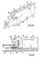
- the connector by displacement of insulator object of the invention comprises at least one elementary connector formed by an elementary connector body noted 1.
- the elementary connector body 1 comprises two side walls 10, 11, parallel delimiting a housing 12.
- the elementary connector body 1 also comprises a contact part 2 with two branches 20, 21, inserted into the housing 12 and having a part in an arc of a circle denoted 22, centered in position relative to a direction ⁇ orthogonal to the elementary connector body 1.
- FIG. 1b it will be noted that only the branch 20 of the contact piece 2 has been shown due to the representation in section along the section plane AA of FIG. 1a, of this same FIG. 1b.
- the elementary connector is also formed by a connection lever denoted 3 rotatably mounted in the housing 12, between the two parallel side walls 10 and 11, relative to the orthogonal direction ⁇ .
- the lever 3 comprises a slot in an arc of a circle denoted 30, capable of being engaged or disengaged from the part of an arc of a circle 22 of the contact piece during the rotational movement of the lever 3, and a cylindrical blind hole 31 or of variable cross section connecting said slot with the outside.
- the blind hole 31 makes it possible to put the slot 30 formed in the connection lever 3 into communication with the housing 12.
- FIGS. 1a and 1b Other details of embodiment of the various constituent elements of the connector which is the subject of the invention as shown in FIGS. 1a and 1b will be described in connection with FIGS. 1b and 1c.
- connection lever 3 is rotatably mounted by the in intermediate of a substantially cylindrical shoulder denoted 32, which forms an articulation with a concave housing 13, formed in the body of the elementary connector 1.
- a concave housing 13 communicates directly with the housing 12 .
- the concave housing 13 comprises two circular sectors noted 130, 131 in FIG. 1c.
- the aforementioned circular sectors form a stop at the opening of the lever 3.
- the connection lever 3 comprises two circular grooves thus shown in FIG. 1c in particular, which are referenced 33 and 34 in FIG. 1c, these grooves being mounted to slide on the sectors circular 130, 131.
- the cylindrical shoulder 32, the concave housing 13, the circular sectors 130, 131 and the grooves 33, 34 are centered on the direction orthogonal to the body of the elementary connector, direction denoted ⁇ forming axis of rotation.
- connection part 2 is also shown, this being provided with its two branches 20 and 21 forming the part in an arc of a circle 22.
- the part of the connection part 2 opposite the part in arc of circle 22 forming the end of the connection piece 2 is advantageously provided with a connection zone 200, which can be connected to a start or end conductor by any means suitable for this purpose.
- the room contact 2 is provided with a lug 201, which advantageously allows the insertion of the contact piece 2 in the elementary connector body 1 by snap-fastening.
- connection piece 2 it is advantageous, first of all to engage the connection piece 2 at the level of the part in an arc 22 thereof in the slot 30 of the connection lever 33, then engage the contact piece, the connection lever 3 being held integral with the latter, in the housing provided in the elementary connector body 1 for inserting the contact piece 2 therein by snap-fastening via the lug 201.
- the cylindrical shoulder 32 is brought into abutment in the concave housing 13, the arc portion of circle 22, the cylindrical shoulder 32, and the concave housing 13 then being automatically centered on the direction ⁇ orthogonal to the elementary connector body 1 and thus forming an articulation for the rotation of the lever.
- the lever 3 is first of all brought into the open position, the connection orifice 31 then being released and being placed substantially above the arcuate part 22 of the contact piece 2.
- the cable connection C can then be introduced into the connection orifice 31, the cable C not being stripped.
- connection lever 3 and the cable C held inside the connection orifice 31 can then be folded down to bring the connection lever 3 into the closed position as shown in FIG. 1e, the cable to be connected C then being engaged in the interval formed by the two branches 20, 21 of the contact piece 2.
- the above-mentioned interval is of course adapted in order to allow the connection lever 3 to be made during the operation of the insulation lever , the central core of the conductor C to be connected then being brought into contact with the branches 20 and 21 to form electrical contact by displacement of the insulator.
- the circular sectors 130, 131 and the cooperating grooves 33 and 34 formed on the connection lever 3 can advantageously be shaped to oppose when the lever 3 is extracted from the housing 12.
- the opening angle of the sectors 130, 131 relative to the so-called horizontal direction corresponding to the longitudinal direction of the connector body can, advantageously, be taken equal at 90 °, as shown in Figures 1b, 1d and 1e in particular.
- the opening angle grooves, or even more precisely the complement of the opening angle of the grooves relative to this same direction can advantageously be between 0 and 45 °, this angle being chosen so that in the open position of the lever connection 3 as shown in FIG.
- connection orifice 31 for a completely free position from the connection orifice 31, the part in an arc of a circle 22 of the connection piece 2 remains however engaged over a sufficient length in the slot 30 of the lever connection 3 to prevent dislocation of the assembly and thus oppose the extraction of the lever 3 from the housing 12, the articulation around the axis ⁇ being completely locked.
- FIGS. 2a and 2b Another advantageous, because simplified, embodiment of the connector by displacement of insulator for a single-conductor cable which is the subject of the invention will be described in connection with FIGS. 2a and 2b.
- the articulation of the lever of connection 3 to connector body 1 has been simplified, as will be described below, this type of connector in accordance with the object of the invention, which can be used in applications in which the degree of insulation of the side faces 10 and 11 may be less important.
- the lever 3 is mounted for rotation in a notch with a circular edge denoted 100.
- the lever 3 comprises a journal denoted 300, forming a cylindrical axis of rotation, engaged in the notch with a circular edge 100.
- L axis of rotation and the circular edge of the notch are centered on the direction ⁇ orthogonal to the elementary connector body 1.
- the side walls 10 and 11 can advantageously be provided with bosses 500 and the connection lever 3 can be provided on its front face, with housings 501 intended to come into abutment on the bosses 500 mentioned above.
- the bosses 500 and the housings 501 can advantageously be shaped so as to block the connection lever 3 in the open position.
- the connector body 1 is shown in a front view of a section made according to a longitudinal plane of symmetry in FIG. 2a, while the connection lever 3 is shown in a view. side of the connection lever shown in Figure 2a.
- the side walls 10 and 11 of the elementary connector body 1 are flexible and have two circular housings denoted 1000, centered on the direction orthogonal to the elementary connector body.
- the connection lever 3 comprises two cylindrical bosses denoted 3000, forming a trunnion of the same diameter as the two circular housings 1000. These cylindrical bosses 3000 forming a trunnion are intended to be engaged in the circular housings 1000 by snap-fastening.
- the side walls 10 and 11 are also provided with bosses 500 forming a stop in the open position of the connection lever 3, the latter itself being provided with housings 501 intended to come into abutment against the aforementioned bosses 500.
- connection lever 3 The characteristics common to the connectors by displacement of insulation to the single-conductor cable object of the invention, relating to the three embodiments previously described will now be given, in particular as regards the connection lever 3.
- connection lever 3 can advantageously include a lever body 35, the transverse dimension of which is parallel to the direction ⁇ ortho gonal to the elementary connector body 1 is substantially equal to that of the housing 12 in the same direction. It may further comprise a lever arm 36, extending longitudinally in the longitudinal direction of the housing 12.
- connection lever 3 and in particular the lever body and the lever arm, respectively referenced 35, 36 are retracted into the housing 12, in the closed position of the connection lever 3.
- a recess denoted 105, respectively 115 can be provided on the lateral faces 10 and 11, so as to facilitate gripping the end of the lever arm 36.
- the blind hole 31 has its connection opening oriented towards the end of the lever arm 36.
- the blind hole 31 can be replaced by a hole passing through the lever body 35.
- the branches 20 and 21 of the contact piece 2 are shaped so as to constitute a groove which is substantially V-shaped.
- the cable to be connected C having been introduced into the connection orifice 31, the cable C to be connected, provided with its insulator, is forcibly inserted into the housing formed by the branches 20 and 21 ensuring on the one hand the electrical connection of the central core of the conductor C with the branches 20 and 21, and on the other hand a mechanical locking of the connection lever 3, by means of the cable, which has been brought into the corner position cement in the V-shaped slot
- the elementary connector body 1 and the connection lever 3 can be made of a material such as a polyamide or polycarbonate material, and obtained by molding.
- the connecting piece 2 can be made of a phosphorous bronze or a beryllium bronze and can advantageously include a protective coating of tin.
- the connector by displacement of insulation for a single-conductor cable which is the subject of the invention is particularly advantageous in that it allows either the connection of a single-conductor cable, a connector then comprising an elementary connector body, or the connection of several cables. single conductors.
- the elementary connectors can be arranged adjacent along their transverse dimension and be fixed mutually, in particular by interlocking or snap-fastening.
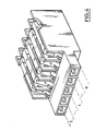
- the connector which is the subject of the invention can be used to produce, as shown in FIG. 4, a terminal block provided with a large number of adjacent elementary connectors according to their transverse dimension.
- the housing 12 of an elementary connector has a side wall 10, 11 common with the corresponding wall dante of the housing 12 of the adjacent elementary connector.
- the terminal block thus lends itself easily to molding in one piece and retains a small transverse dimension.
- the terminal block has, due to the above structure, a high degree of insulation of the various contact parts and a high degree of compactness.
Landscapes
- Details Of Connecting Devices For Male And Female Coupling (AREA)
- Connector Housings Or Holding Contact Members (AREA)
Applications Claiming Priority (2)
| Application Number | Priority Date | Filing Date | Title |
|---|---|---|---|
| FR8617495 | 1986-12-15 | ||
| FR8617495A FR2608326B1 (fr) | 1986-12-15 | 1986-12-15 | Connecteur par deplacement d'isolant pour cable monoconducteur |
Publications (2)
| Publication Number | Publication Date |
|---|---|
| EP0274948A1 true EP0274948A1 (de) | 1988-07-20 |
| EP0274948B1 EP0274948B1 (de) | 1992-09-30 |
Family
ID=9341887
Family Applications (1)
| Application Number | Title | Priority Date | Filing Date |
|---|---|---|---|
| EP87402841A Expired - Lifetime EP0274948B1 (de) | 1986-12-15 | 1987-12-14 | Schneidklemmenverbinder für Monoleitungskabel |
Country Status (3)
| Country | Link |
|---|---|
| EP (1) | EP0274948B1 (de) |
| DE (1) | DE3782023T2 (de) |
| FR (1) | FR2608326B1 (de) |
Cited By (5)
| Publication number | Priority date | Publication date | Assignee | Title |
|---|---|---|---|---|
| US4957452A (en) * | 1988-12-14 | 1990-09-18 | Oskar Wortz & Inhaber Hans Woretz | Electrical terminal |
| GB2290174A (en) * | 1994-06-02 | 1995-12-13 | Mod Tap W Corp | Contacts for insulation displacement connectors |
| WO1999065113A1 (de) * | 1998-06-08 | 1999-12-16 | Siemens Aktiengesellschaft | Schneidklemme |
| US6152759A (en) * | 1998-12-21 | 2000-11-28 | Lucent Technologies Inc. | Strain relief mechanism for an insulation displacement connector |
| DE202005014719U1 (de) * | 2005-09-17 | 2007-02-01 | Weidmüller Interface GmbH & Co. KG | Anschluß-System zur Realisierung von Abzweigungen an durchgehenden Leitern |
Families Citing this family (2)
| Publication number | Priority date | Publication date | Assignee | Title |
|---|---|---|---|---|
| DE19921775B4 (de) * | 1999-05-11 | 2011-06-01 | Phoenix Contact Gmbh & Co. Kg | Verbindungsklemme in Schneid-Klemmtechnik |
| ES2316227B1 (es) * | 2006-03-21 | 2009-10-19 | Simon, S.A. | Perfeccionamientos introducidos en los sistemas de embornado por enclavamiento, aplicables a dispositivos electricos. |
Citations (3)
| Publication number | Priority date | Publication date | Assignee | Title |
|---|---|---|---|---|
| DE2902536B1 (de) * | 1979-01-24 | 1980-04-24 | Weidmueller Kg C | Reihenklemme |
| EP0099008A2 (de) * | 1982-07-13 | 1984-01-25 | Karl Lumberg GmbH & Co. | Anschlussleiste |
| FR2575609A1 (fr) * | 1985-01-03 | 1986-07-04 | Nozick Jacques | Borne de connexion pour cables metalliques |
-
1986
- 1986-12-15 FR FR8617495A patent/FR2608326B1/fr not_active Expired
-
1987
- 1987-12-14 EP EP87402841A patent/EP0274948B1/de not_active Expired - Lifetime
- 1987-12-14 DE DE8787402841T patent/DE3782023T2/de not_active Expired - Fee Related
Patent Citations (3)
| Publication number | Priority date | Publication date | Assignee | Title |
|---|---|---|---|---|
| DE2902536B1 (de) * | 1979-01-24 | 1980-04-24 | Weidmueller Kg C | Reihenklemme |
| EP0099008A2 (de) * | 1982-07-13 | 1984-01-25 | Karl Lumberg GmbH & Co. | Anschlussleiste |
| FR2575609A1 (fr) * | 1985-01-03 | 1986-07-04 | Nozick Jacques | Borne de connexion pour cables metalliques |
Cited By (8)
| Publication number | Priority date | Publication date | Assignee | Title |
|---|---|---|---|---|
| US4957452A (en) * | 1988-12-14 | 1990-09-18 | Oskar Wortz & Inhaber Hans Woretz | Electrical terminal |
| DE3938351C2 (de) * | 1988-12-14 | 1999-10-14 | Woertz Oskar | Elektrische Klemme |
| GB2290174A (en) * | 1994-06-02 | 1995-12-13 | Mod Tap W Corp | Contacts for insulation displacement connectors |
| US6036527A (en) * | 1994-06-02 | 2000-03-14 | Molex Incorporated | Contacts for insulation displacement connectors |
| WO1999065113A1 (de) * | 1998-06-08 | 1999-12-16 | Siemens Aktiengesellschaft | Schneidklemme |
| US6152759A (en) * | 1998-12-21 | 2000-11-28 | Lucent Technologies Inc. | Strain relief mechanism for an insulation displacement connector |
| DE202005014719U1 (de) * | 2005-09-17 | 2007-02-01 | Weidmüller Interface GmbH & Co. KG | Anschluß-System zur Realisierung von Abzweigungen an durchgehenden Leitern |
| US7234961B2 (en) | 2005-09-17 | 2007-06-26 | Weidmüller Interface GmbH & Co. KG | Connector arrangement including insulated conductor tap-off means |
Also Published As
| Publication number | Publication date |
|---|---|
| FR2608326A1 (fr) | 1988-06-17 |
| DE3782023T2 (de) | 1993-02-18 |
| FR2608326B1 (fr) | 1989-03-31 |
| EP0274948B1 (de) | 1992-09-30 |
| DE3782023D1 (de) | 1992-11-05 |
Similar Documents
| Publication | Publication Date | Title |
|---|---|---|
| EP0271413B1 (de) | Isolationsverschiebungssteckverbinder für Einzelleiterkabel | |
| EP2315315B1 (de) | Koaxialer sockel | |
| EP0464767A1 (de) | Aus zwei über ein Gelenk und elektrisch verbundenen Elementen bestehendes Gerät | |
| EP0580505A1 (de) | Anpassungssystem zwischen einem Antennenstecker und der Buchse eines Funktelefons | |
| EP0274948B1 (de) | Schneidklemmenverbinder für Monoleitungskabel | |
| FR2853997A1 (fr) | Piece de contact pour connecteur electrique | |
| EP0500466A2 (de) | Verschluss für die Kontaktaufnahme eines elektrischen oder optischen Steckverbinders | |
| EP0060187B1 (de) | Elektrische Verbindungsvorrichtung zum Anschluss von mehradrigen Kabeln | |
| EP0251909B1 (de) | Verbindungselement für ein elektrisches Monoleiterkabel zur axialen Verbindung | |
| FR2783099A1 (fr) | Ensemble de connexion hermetique | |
| EP1588460B1 (de) | Ellbogenförmiger elektrischer stecker | |
| FR2593969A1 (fr) | Dispositif de connexion auto-denudant | |
| EP0157060A1 (de) | Selbstabisolierende Verbindungsvorrichtung für elektrische Leiter | |
| EP3255732B1 (de) | Elektrische verbindungsklemme, die einen verbindungshebel umfasst, und entsprechende elektrische geräte | |
| EP1422790B1 (de) | Koaxialverbinder, insbesondere 7/16 genormter Verbinder | |
| FR2716578A1 (fr) | Connecteur à contact à déplacement d'isolant. | |
| FR2524211A1 (fr) | Connecteur electrique | |
| EP1286427A1 (de) | Reihenklemme mit Verriegelungshebel für Steckverbinder | |
| WO2007110312A1 (fr) | Connecteur basse tension | |
| FR2705502A1 (fr) | Connecteur électrique antidéflagrant. | |
| EP2367238B1 (de) | Niederspannungsstecker für Kommunikationssystem | |
| FR2622362A1 (fr) | Connecteur autodenudant pour conducteur electrique isole | |
| BE857590R (fr) | Connecteur pour cable plat | |
| FR2723265A1 (fr) | Borne de connexion electrique | |
| FR2790875A1 (fr) | Dispositif connecteur a fiches electrique |
Legal Events
| Date | Code | Title | Description |
|---|---|---|---|
| PUAI | Public reference made under article 153(3) epc to a published international application that has entered the european phase |
Free format text: ORIGINAL CODE: 0009012 |
|
| AK | Designated contracting states |
Kind code of ref document: A1 Designated state(s): DE |
|
| 17P | Request for examination filed |
Effective date: 19880905 |
|
| RAP1 | Party data changed (applicant data changed or rights of an application transferred) |
Owner name: TELEMECANIQUE |
|
| RAP1 | Party data changed (applicant data changed or rights of an application transferred) |
Owner name: TELEMECANIQUE |
|
| 17Q | First examination report despatched |
Effective date: 19910118 |
|
| GRAA | (expected) grant |
Free format text: ORIGINAL CODE: 0009210 |
|
| AK | Designated contracting states |
Kind code of ref document: B1 Designated state(s): DE |
|
| REF | Corresponds to: |
Ref document number: 3782023 Country of ref document: DE Date of ref document: 19921105 |
|
| PLBE | No opposition filed within time limit |
Free format text: ORIGINAL CODE: 0009261 |
|
| STAA | Information on the status of an ep patent application or granted ep patent |
Free format text: STATUS: NO OPPOSITION FILED WITHIN TIME LIMIT |
|
| 26N | No opposition filed | ||
| PGFP | Annual fee paid to national office [announced via postgrant information from national office to epo] |
Ref country code: DE Payment date: 20001111 Year of fee payment: 14 |
|
| PG25 | Lapsed in a contracting state [announced via postgrant information from national office to epo] |
Ref country code: DE Free format text: LAPSE BECAUSE OF NON-PAYMENT OF DUE FEES Effective date: 20020702 |