EP0275357A1 - Vanne pour conduite - Google Patents
Vanne pour conduite Download PDFInfo
- Publication number
- EP0275357A1 EP0275357A1 EP87112618A EP87112618A EP0275357A1 EP 0275357 A1 EP0275357 A1 EP 0275357A1 EP 87112618 A EP87112618 A EP 87112618A EP 87112618 A EP87112618 A EP 87112618A EP 0275357 A1 EP0275357 A1 EP 0275357A1
- Authority
- EP
- European Patent Office
- Prior art keywords
- closure member
- sleeve
- spindle
- fitting according
- length section
- Prior art date
- Legal status (The legal status is an assumption and is not a legal conclusion. Google has not performed a legal analysis and makes no representation as to the accuracy of the status listed.)
- Granted
Links
- 239000002184 metal Substances 0.000 claims abstract description 23
- 238000010348 incorporation Methods 0.000 claims abstract description 3
- 238000007789 sealing Methods 0.000 abstract description 11
- 238000006073 displacement reaction Methods 0.000 abstract 2
- 238000012856 packing Methods 0.000 description 5
- 210000004907 gland Anatomy 0.000 description 4
- 230000006835 compression Effects 0.000 description 2
- 238000007906 compression Methods 0.000 description 2
- 238000003466 welding Methods 0.000 description 2
- 238000011109 contamination Methods 0.000 description 1
- 230000008878 coupling Effects 0.000 description 1
- 238000010168 coupling process Methods 0.000 description 1
- 238000005859 coupling reaction Methods 0.000 description 1
- 230000007613 environmental effect Effects 0.000 description 1
- 230000029142 excretion Effects 0.000 description 1
- 238000000034 method Methods 0.000 description 1
- 230000007935 neutral effect Effects 0.000 description 1
- 210000000056 organ Anatomy 0.000 description 1
Images

Classifications
-
- F—MECHANICAL ENGINEERING; LIGHTING; HEATING; WEAPONS; BLASTING
- F16—ENGINEERING ELEMENTS AND UNITS; GENERAL MEASURES FOR PRODUCING AND MAINTAINING EFFECTIVE FUNCTIONING OF MACHINES OR INSTALLATIONS; THERMAL INSULATION IN GENERAL
- F16K—VALVES; TAPS; COCKS; ACTUATING-FLOATS; DEVICES FOR VENTING OR AERATING
- F16K41/00—Spindle sealings
- F16K41/10—Spindle sealings with diaphragm, e.g. shaped as bellows or tube
-
- F—MECHANICAL ENGINEERING; LIGHTING; HEATING; WEAPONS; BLASTING
- F16—ENGINEERING ELEMENTS AND UNITS; GENERAL MEASURES FOR PRODUCING AND MAINTAINING EFFECTIVE FUNCTIONING OF MACHINES OR INSTALLATIONS; THERMAL INSULATION IN GENERAL
- F16K—VALVES; TAPS; COCKS; ACTUATING-FLOATS; DEVICES FOR VENTING OR AERATING
- F16K3/00—Gate valves or sliding valves, i.e. cut-off apparatus with closing members having a sliding movement along the seat for opening and closing
- F16K3/02—Gate valves or sliding valves, i.e. cut-off apparatus with closing members having a sliding movement along the seat for opening and closing with flat sealing faces; Packings therefor
- F16K3/12—Gate valves or sliding valves, i.e. cut-off apparatus with closing members having a sliding movement along the seat for opening and closing with flat sealing faces; Packings therefor with wedge-shaped arrangements of sealing faces
Definitions
- the invention relates to a pipe fitting according to the features in the preamble of claim 1.
- Such a fitting has a spindle which is axially immovable in the fitting housing.
- the threaded section is provided at the lower end and the closure member is equipped with a recess into which the threaded section can be immersed during the opening process.
- the known design has a comparatively high housing attachment.
- the reason for this is the necessity to have to move the closure member completely out of the flow cross-section, in connection with the requirement to extend the area of extension of the spindle between the closure member and the entry into the housing attachment with regard to the aggressive and / or polluting media to have to seal properly with a metal bellows.
- the length of such a metal bellows inevitably increases with the nominal size of the valve.
- a longer metal bellows in turn means a higher housing attachment.
- Adjustment of the above peculiarities results from a gate valve of z. B. DN 150 a total height of more than 2 m. The space required for this is, however, not available in many cases.
- the effort for the provision of a housing that meets the respective requirements, in particular the housing attachment also increases automatically.
- the object of the invention is to improve the pipeline fitting described in the preamble of claim 1 with an axially non-displaceable spindle in such a way that its vertical extension can be considerably reduced, especially for the housing attachment, at reduced cost.
- the flexibility of the length sections of the metal bellows can be dimensioned the same.
- the embodiment of claim 2, however, provides that the longitudinal sections have a different axial flexibility.
- the sleeve acts as a link between the two lengths.
- the length sections on the sleeve are fixed in particular by welding.
- the sleeve has a guiding function for both the inner and the outer length section.
- a radial flange can be provided on the free edge of the sleeve, to which the outer length section is then welded.
- the tubular connecting piece according to claim 4 also has a stop function for the sleeve in the sense of an axial limitation of the compression of the metal bellows.
- a preferred embodiment of the invention consists in the features of claim 5.
- the spindle nut integrated in the closure member can now be properly separated from the medium flowing through the pipeline fitting.
- excretions or contamination of the medium can no longer attach to the spindle nut, which has previously led to a failure of the valve in some applications.
- the upper end of the outer length section is expediently carried out in such a way that a washer welded to this length section is clamped between two seals in the cover flange connection.
- the tubular connecting piece according to claim 6 also has a stop function for the sleeve in the sense of an axial limitation of the compression and stretching length of the two longitudinal sections of the metal bellows from their neutral positions.
- the collars are also designed and positioned in such a way that the length sections are not deformed inadmissibly neither in depressurized operation nor in underpressure or overpressure operation.
- a cross bolt is used for coupling the lifting tube and the end member.
- the bottom of the lifting tube is suitably thickened.
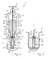
- the gate valve 1 of Figure 1 has a lower housing part 2 with sealing seats 3 for a closure member in the form of a wedge-shaped slide 4.
- a housing attachment 7 is detachably connected to the lower housing part 2 by means of screw bolts 5 with the incorporation of a tubular intermediate piece 6.
- a threaded section 10 is arranged, which engages in a form-fitting manner in a spindle nut 11 which is fastened to the head end of the closure member 4.
- the handwheel 9 rotates, the spindle nut 11 consequently moves along the threaded section 10 together with the closure member 4.
- the threaded section 10 is immersed in a recess 12 in the closure member 4 when the latter is moved into the open position.
- a safety stuffing box 14 is provided in a neck-shaped extension 13 of the housing attachment 7.
- the gland packing 15 can be tightened with the aid of screw bolts 16 pivotably mounted on the housing neck 13 and the gland packing 17 and a pressure ring 18.
- the extent of the spindle 8 between the closure member 4 and the housing attachment 7 is encased by a metal bellows 21 consisting of two length sections 19, 20.
- the longitudinal sections 19, 20 are telescopically nested concentrically one inside the other. It can be seen that the inner length section 19 is fixed at one end 22 to the spindle nut 11 and at the other end 23 at the bottom 24 of a sleeve 25 surrounding the inner length section 19 by welding.
- the sleeve 25 is guided in the interior of a tubular connecting piece 26 which extends from the housing attachment 7 in the direction of the closure member 4.
- the connector 26 is welded to the housing attachment 7.
- the circumferential side of the connector 26 is the outer length section 20, which is welded to one end 27 on the housing attachment 7 and the other end 28 to a radial flange 29 of the sleeve 25.
- the maximum axial compressibility of the metal bellows 21 is determined by the stop 30 of the spindle nut 11 in connection with the radial collar 29 of the sleeve 25 and the end face 31 of the socket 26.
- the gate valve 1 ⁇ of Figures 2 and 3 also has a lower housing part 2 ⁇ with sealing seats 3 ⁇ for a closure member in the form of a wedge-shaped slide 4 ⁇ .
- An intermediate piece 6 ⁇ is detachably connected to the lower housing part 2 ⁇ by means of screw bolts 5 ⁇ and a housing attachment 7 ⁇ is detachably connected to the upper end of the intermediate piece 6 ⁇ by means of screw bolts 5 ⁇ .
- the determination is made via a cross bolt 34 which passes through the closure member 33 and the lifting tube 32 at the lower end of the closure member 4 ⁇ .
- the closure member 33 is vertically displaceable along lateral constrained guides 35 in the lower housing part 2 ⁇ .
- the spindle nut 11 ⁇ moves along the threaded section 10 together with the locking member 4glied.
- the threaded portion 10 of the spindle 8 is immersed in the interior 36 of the lifting tube 32 when the closure member 4 ⁇ is moved into the open position.
- a safety stuffing box In a neck-like extension 13 ⁇ of the housing attachment 7 ⁇ a safety stuffing box, not shown, is provided.
- the packing in this stuffing box can be tightened with the aid of screw bolts, also not shown, a stuffing box goggle and a pressure ring according to the embodiment in FIG. 1.
- the area of extension of the spindle 8 between the closure member 4 ⁇ and the housing attachment 7 ⁇ is encased by a metal bellows 21 ⁇ consisting of two longitudinal sections 19 ⁇ , 20 ⁇ .
- the longitudinal sections 19 ⁇ , 20 ⁇ are telescopically nested concentrically one inside the other. It can be seen that the end of the inner longitudinal section 19 ⁇ facing away from the closure member 4 ⁇ is fastened to the bottom 37 of a sleeve 38 enclosing the inner longitudinal section 19 ⁇ and enclosed by the outer longitudinal section 20 ⁇ .
- the other end of the inner length portion 19 ⁇ is fixed to a collar 39 of the lifting tube 32.
- the end of the outer length portion 20 ⁇ facing the closure member 4 ⁇ is tightly attached to the lower free edge 40 of the sleeve 38 and the other end to the cover flange connection 5 ⁇ .
- the outer length section 20 ⁇ can be welded to a disk 41, which can be tightly fixed between the housing attachment 7 ⁇ and the intermediate piece 6 ⁇ .
- the sleeve 38 is guided with its lower end on the outside of a tubular stub 42 extending from the closure member 4 ⁇ in the direction of the housing attachment 7 ⁇ and with its upper end 37 on the spindle 8.
- a radially inwardly directed collar 43 is provided at the lower end of the sleeve 38 and a radially outwardly directed collar 44 is provided at the upper end of the connecting piece 42.
- the collar 44 is always between the collar 43 and the bottom 37 of the sleeve 38.
- the longitudinal sections 19 ⁇ , 20 ⁇ of the metal bellows 21 ⁇ can have a different axial flexibility.
Landscapes
- Engineering & Computer Science (AREA)
- General Engineering & Computer Science (AREA)
- Mechanical Engineering (AREA)
- Details Of Valves (AREA)
Applications Claiming Priority (4)
| Application Number | Priority Date | Filing Date | Title |
|---|---|---|---|
| DE19863643926 DE3643926A1 (de) | 1986-12-22 | 1986-12-22 | Rohrleitungsarmatur |
| DE3643926 | 1986-12-22 | ||
| DE8710327U DE8710327U1 (de) | 1987-07-28 | 1987-07-28 | Rohrleitungsarmatur |
| DE8710327U | 1987-07-28 |
Publications (2)
| Publication Number | Publication Date |
|---|---|
| EP0275357A1 true EP0275357A1 (fr) | 1988-07-27 |
| EP0275357B1 EP0275357B1 (fr) | 1990-08-08 |
Family
ID=25850699
Family Applications (1)
| Application Number | Title | Priority Date | Filing Date |
|---|---|---|---|
| EP19870112618 Expired - Lifetime EP0275357B1 (fr) | 1986-12-22 | 1987-08-29 | Vanne pour conduite |
Country Status (2)
| Country | Link |
|---|---|
| EP (1) | EP0275357B1 (fr) |
| ES (1) | ES2016311B3 (fr) |
Cited By (1)
| Publication number | Priority date | Publication date | Assignee | Title |
|---|---|---|---|---|
| EP0984216A3 (fr) * | 1998-09-03 | 2001-06-27 | Präzisionsarmaturen Ostfalenpark Barleben GmbH | Dispositif de fermeture pour conduit |
Citations (2)
| Publication number | Priority date | Publication date | Assignee | Title |
|---|---|---|---|---|
| DE703985C (de) * | 1938-05-17 | 1941-03-20 | Aeg | Balgmembrandichtung an der Spindeldurchfuehrung von Ventilen |
| DE1023942B (de) * | 1957-01-04 | 1958-02-06 | Theo Schulte Fa | Zwischenstuecke mit Halsansatz fuer stopfbuechslose Armaturen |
-
1987
- 1987-08-29 ES ES87112618T patent/ES2016311B3/es not_active Expired - Lifetime
- 1987-08-29 EP EP19870112618 patent/EP0275357B1/fr not_active Expired - Lifetime
Patent Citations (2)
| Publication number | Priority date | Publication date | Assignee | Title |
|---|---|---|---|---|
| DE703985C (de) * | 1938-05-17 | 1941-03-20 | Aeg | Balgmembrandichtung an der Spindeldurchfuehrung von Ventilen |
| DE1023942B (de) * | 1957-01-04 | 1958-02-06 | Theo Schulte Fa | Zwischenstuecke mit Halsansatz fuer stopfbuechslose Armaturen |
Cited By (1)
| Publication number | Priority date | Publication date | Assignee | Title |
|---|---|---|---|---|
| EP0984216A3 (fr) * | 1998-09-03 | 2001-06-27 | Präzisionsarmaturen Ostfalenpark Barleben GmbH | Dispositif de fermeture pour conduit |
Also Published As
| Publication number | Publication date |
|---|---|
| EP0275357B1 (fr) | 1990-08-08 |
| ES2016311B3 (es) | 1990-11-01 |
Similar Documents
| Publication | Publication Date | Title |
|---|---|---|
| DE3688332T2 (de) | Balgdichtungsventil. | |
| EP2252819B1 (fr) | Dispositif pour relier un boîtier de soupape à un mécanisme de commande pour soupape de traitement fonctionnant comme soupape de levage | |
| EP0992717A2 (fr) | Anneau d'étanchéité plat | |
| DE102012003397A1 (de) | Kükenhahn mit einem drehzapfengelagerten Küken | |
| DE3436254C2 (de) | Verfahren und Dichtung zum Verbinden von Rohrenden einer bereits benutzten Gasleitung | |
| CH656932A5 (de) | Absperrventil. | |
| DE2528546A1 (de) | Schieberventil | |
| EP1155250B1 (fr) | Robinet | |
| DE2113415C3 (de) | Absperrschieber | |
| DE2832439A1 (de) | Ringdichtung, insbesondere fuer absperrorgane mit kugelfoermigem absperrkoerper | |
| DE4130870C2 (de) | Hydraulischer, regelbarer Schwingungsdämpfer | |
| WO2020011502A1 (fr) | Dispositif distributeur rotatif doté d'un agencement d'étanchéité | |
| EP0275357A1 (fr) | Vanne pour conduite | |
| EP0077058B1 (fr) | Robinet à boisseau sphérique | |
| DE102017123376B4 (de) | Ventilantriebssystem für ein pneumatisches oder hydraulisches Ventil | |
| DE2147134C3 (de) | Füllkopf für einen Druckgas- oder Flüssiggasbehälter | |
| DE3828561C2 (de) | Absperrschieber | |
| DE1034937B (de) | Absperrschieber mit einem Verschlussstueck aus elastischem Material mit schlauchartiger Fortsetzung auf der Spindelseite | |
| DE10052505A1 (de) | Unterflurhydrant mit rohrförmigem Ventilsitzring | |
| DE69508865T2 (de) | Ventil mit Verschlusselement und Membran | |
| DE1550468B2 (de) | Doppelsitzventil | |
| DE202016004959U1 (de) | Schlauchanschlussvorrichtung | |
| DE4100862A1 (de) | Absperrschieber | |
| EP4078002A1 (fr) | Raccord rapide pour raccordement | |
| DE3643926C2 (fr) |
Legal Events
| Date | Code | Title | Description |
|---|---|---|---|
| PUAI | Public reference made under article 153(3) epc to a published international application that has entered the european phase |
Free format text: ORIGINAL CODE: 0009012 |
|
| AK | Designated contracting states |
Kind code of ref document: A1 Designated state(s): BE ES FR IT NL SE |
|
| 17P | Request for examination filed |
Effective date: 19880820 |
|
| 17Q | First examination report despatched |
Effective date: 19890623 |
|
| GRAA | (expected) grant |
Free format text: ORIGINAL CODE: 0009210 |
|
| AK | Designated contracting states |
Kind code of ref document: B1 Designated state(s): BE ES FR IT NL SE |
|
| ITF | It: translation for a ep patent filed | ||
| ET | Fr: translation filed | ||
| PLBE | No opposition filed within time limit |
Free format text: ORIGINAL CODE: 0009261 |
|
| STAA | Information on the status of an ep patent application or granted ep patent |
Free format text: STATUS: NO OPPOSITION FILED WITHIN TIME LIMIT |
|
| 26N | No opposition filed | ||
| ITTA | It: last paid annual fee | ||
| EAL | Se: european patent in force in sweden |
Ref document number: 87112618.1 |
|
| PGFP | Annual fee paid to national office [announced via postgrant information from national office to epo] |
Ref country code: SE Payment date: 19990805 Year of fee payment: 13 |
|
| PGFP | Annual fee paid to national office [announced via postgrant information from national office to epo] |
Ref country code: FR Payment date: 19990811 Year of fee payment: 13 |
|
| PGFP | Annual fee paid to national office [announced via postgrant information from national office to epo] |
Ref country code: ES Payment date: 19990820 Year of fee payment: 13 |
|
| PGFP | Annual fee paid to national office [announced via postgrant information from national office to epo] |
Ref country code: BE Payment date: 19990824 Year of fee payment: 13 |
|
| PGFP | Annual fee paid to national office [announced via postgrant information from national office to epo] |
Ref country code: NL Payment date: 19990831 Year of fee payment: 13 |
|
| PG25 | Lapsed in a contracting state [announced via postgrant information from national office to epo] |
Ref country code: SE Free format text: LAPSE BECAUSE OF NON-PAYMENT OF DUE FEES Effective date: 20000830 Ref country code: ES Free format text: LAPSE BECAUSE OF NON-PAYMENT OF DUE FEES Effective date: 20000830 |
|
| PG25 | Lapsed in a contracting state [announced via postgrant information from national office to epo] |
Ref country code: BE Free format text: LAPSE BECAUSE OF NON-PAYMENT OF DUE FEES Effective date: 20000831 |
|
| BERE | Be: lapsed |
Owner name: SIEPMANN-WERKE G.M.B.H. & CO. K.G. Effective date: 20000831 |
|
| PG25 | Lapsed in a contracting state [announced via postgrant information from national office to epo] |
Ref country code: NL Free format text: LAPSE BECAUSE OF NON-PAYMENT OF DUE FEES Effective date: 20010301 |
|
| EUG | Se: european patent has lapsed |
Ref document number: 87112618.1 |
|
| PG25 | Lapsed in a contracting state [announced via postgrant information from national office to epo] |
Ref country code: FR Free format text: LAPSE BECAUSE OF NON-PAYMENT OF DUE FEES Effective date: 20010430 |
|
| NLV4 | Nl: lapsed or anulled due to non-payment of the annual fee |
Effective date: 20010301 |
|
| REG | Reference to a national code |
Ref country code: FR Ref legal event code: ST |
|
| REG | Reference to a national code |
Ref country code: ES Ref legal event code: FD2A Effective date: 20010911 |
|
| PG25 | Lapsed in a contracting state [announced via postgrant information from national office to epo] |
Ref country code: IT Free format text: LAPSE BECAUSE OF NON-PAYMENT OF DUE FEES;WARNING: LAPSES OF ITALIAN PATENTS WITH EFFECTIVE DATE BEFORE 2007 MAY HAVE OCCURRED AT ANY TIME BEFORE 2007. THE CORRECT EFFECTIVE DATE MAY BE DIFFERENT FROM THE ONE RECORDED. Effective date: 20050829 |