EP0275793A1 - Vorrichtung zum Montieren eines Schneideinsatzes an einem Werkzeughalter - Google Patents
Vorrichtung zum Montieren eines Schneideinsatzes an einem Werkzeughalter Download PDFInfo
- Publication number
- EP0275793A1 EP0275793A1 EP87402986A EP87402986A EP0275793A1 EP 0275793 A1 EP0275793 A1 EP 0275793A1 EP 87402986 A EP87402986 A EP 87402986A EP 87402986 A EP87402986 A EP 87402986A EP 0275793 A1 EP0275793 A1 EP 0275793A1
- Authority
- EP
- European Patent Office
- Prior art keywords
- tool holder
- screw
- insert
- plate
- hole
- Prior art date
- Legal status (The legal status is an assumption and is not a legal conclusion. Google has not performed a legal analysis and makes no representation as to the accuracy of the status listed.)
- Granted
Links
Images
Classifications
-
- B—PERFORMING OPERATIONS; TRANSPORTING
- B23—MACHINE TOOLS; METAL-WORKING NOT OTHERWISE PROVIDED FOR
- B23B—TURNING; BORING
- B23B27/00—Tools for turning or boring machines; Tools of a similar kind in general; Accessories therefor
- B23B27/14—Cutting tools of which the bits or tips or cutting inserts are of special material
- B23B27/16—Cutting tools of which the bits or tips or cutting inserts are of special material with exchangeable cutting bits or cutting inserts, e.g. able to be clamped
- B23B27/1662—Cutting tools of which the bits or tips or cutting inserts are of special material with exchangeable cutting bits or cutting inserts, e.g. able to be clamped with plate-like cutting inserts clamped against the walls of the recess in the shank by a clamping member acting upon the wall of a hole in the cutting insert
-
- B—PERFORMING OPERATIONS; TRANSPORTING
- B23—MACHINE TOOLS; METAL-WORKING NOT OTHERWISE PROVIDED FOR
- B23B—TURNING; BORING
- B23B2205/00—Fixation of cutting inserts in holders
- B23B2205/04—Fixation screws, bolts or pins of particular form
-
- Y—GENERAL TAGGING OF NEW TECHNOLOGICAL DEVELOPMENTS; GENERAL TAGGING OF CROSS-SECTIONAL TECHNOLOGIES SPANNING OVER SEVERAL SECTIONS OF THE IPC; TECHNICAL SUBJECTS COVERED BY FORMER USPC CROSS-REFERENCE ART COLLECTIONS [XRACs] AND DIGESTS
- Y10—TECHNICAL SUBJECTS COVERED BY FORMER USPC
- Y10T—TECHNICAL SUBJECTS COVERED BY FORMER US CLASSIFICATION
- Y10T407/00—Cutters, for shaping
- Y10T407/22—Cutters, for shaping including holder having seat for inserted tool
- Y10T407/2272—Cutters, for shaping including holder having seat for inserted tool with separate means to fasten tool to holder
- Y10T407/2274—Apertured tool
- Y10T407/2276—Apertured tool with means projecting through aperture to force tool laterally against reaction surface
-
- Y—GENERAL TAGGING OF NEW TECHNOLOGICAL DEVELOPMENTS; GENERAL TAGGING OF CROSS-SECTIONAL TECHNOLOGIES SPANNING OVER SEVERAL SECTIONS OF THE IPC; TECHNICAL SUBJECTS COVERED BY FORMER USPC CROSS-REFERENCE ART COLLECTIONS [XRACs] AND DIGESTS
- Y10—TECHNICAL SUBJECTS COVERED BY FORMER USPC
- Y10T—TECHNICAL SUBJECTS COVERED BY FORMER US CLASSIFICATION
- Y10T407/00—Cutters, for shaping
- Y10T407/22—Cutters, for shaping including holder having seat for inserted tool
- Y10T407/2272—Cutters, for shaping including holder having seat for inserted tool with separate means to fasten tool to holder
- Y10T407/2274—Apertured tool
- Y10T407/2276—Apertured tool with means projecting through aperture to force tool laterally against reaction surface
- Y10T407/2278—Tilting clamp element and separate means to tilt same
Definitions
- the present invention relates to a device for the removable fixing of a cutting insert on a tool holder.
- Such a device is known in particular from French patent 2,109,189.
- the tool holder has a bearing face and two abutment faces in the form of a dihedral perpendicular to said bearing face, for receiving the insert.
- This known device comprises a screw, the threaded rod of which can be screwed into a tapped hole in the tool holder passes through a cylindrical hole in the insert which is eccentric when the latter is properly positioned in contact with the aforementioned faces and without the wall of this eccentric hole touches the stem of the screw.
- the head of this screw has a frustoconical bearing cooperating with an angular portion of a frustoconical bearing also bordering the eccentric hole of the insert in order to press the sides thereof against the abutment faces of the tool holder and concomitantly to tighten said plate against the bearing face of said tool holder.
- the object of the present invention is to improve this fixation so that the insert is perfectly integrated with the tool holder and that no vibration appears between them under the effect of the stresses to which said insert is subjected during cutting.
- the screw head comprises, from the rod to constitute a contact surface with the wafer: - a frustoconical bearing surface of small longitudinal extent which is provided, by cooperating with the edge of the eccentric hole of the insert to approach the side (s) of said insert, of the abutment face (s) of the tool holder and to start pressing them '' one against the other by bending the screw rod, - A substantially cylindrical bearing surface which is provided, by cooperating with the wall of the eccentric hole of the plate to further press said flanks against said short sides waxing the bending cantilever (p) of said rod for a substantially constant deflection, - And a shoulder projecting from the eccentric hole of the insert and which is intended to clamp it against the bearing face of the tool holder.
- the shoulder of the screw head is frustoconical and provided, by cooperating with the eccentric edge of the insert, to progressively press said insert against the bearing face of the tool holder.
- the abutment face (s) of the tool holder are, between the clearance located near the bearing face and its or their outer edge, in clearance between 15 minutes and one degree so that the flanks of the insert bear first against the outer edge of the said abutment face (s).
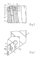
- the cutting insert 1 is positioned in a housing 2 of a tool holder 3 and it is to fix it firmly and precisely without play in said housing relative to said tool holder.
- the plate 1 has the shape of a right prism based on a diamond and therefore its base 4 is normally placed on a bearing face 5 of the housing 2 of the tool holder, while its sides 6 and 7 are applied against the abutment faces 8 and 9 respectively of said housing.
- a tapped hole 10 is machined in the tool holder 3 perpendicular to the bearing face 5 and substantially in the center of the insert 1.
- the latter delimits a cylindrical hole 11 (FIGS. 2 to 5) whose axis 12 is eccentric relative to the axis 13 of the threaded hole 10 when the sides 6 and 7 of said insert are in contact with the abutment faces 8 and 9 of the housing 2 of the tool holder 3.
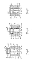
- the threaded rod 14 of a fixing screw 15 does not touch the wall of the hole 11 of the wafer when this rod is screwed into the tapped hole 10 and the head 16 of the said screw is located outside of this hole 11 (FIG. 3).
- the head 16 has a particular shape and comprises, from the rod 14, a frustoconical bearing 17, a substantially cylindrical bearing 18 and a shoulder 19. These different parts 17 to 19 of the head are dimensioned relative to the diameter of the hole 11 , at the eccentricity "e" of this hole relative to the tapped hole 10, to the diameter of the threaded rod 14 and to the thickness of the wafer 1, so that the screw 16 intervenes during its screwing according to different successive phases illustrated by Figures 3 to 5 and described below.
- the frustoconical bearing 17 the slope of which "a" relative to the axis may be between 42 and 44 degrees, comes into contact with the arcuate part 20 of the outer edge of the hole 11, closest to the faces 6 and 7 and causes, because of its slope, first bringing the sides 6 and 7 of the insert into contact with the abutment faces 8 and 9 of the housing 2 of the tool holder and then when this contact is established, the bending of the rod 14 of the screw 15, the axis 13 of which begins to bend as illustrated in FIG. 4 for the next phase. Consequently, the plate 1 is found, by reaction to the elastic deformation of the rod 14, applied firmly against the abutment faces 8 and 9 of the housing 2 of the tool holder.
- the shoulder 19 is frustoconical so that due to its slope "b", the tightening of the insert on the tool holder is progressive.
- This slope can be for example 20 degrees.
- a clearance 23 (FIG. 2) in the abutment faces 8 and 9, flush with the face of support 5.
- a small draft "d" for that the sides 8 and 9 of the plate bear first against the outer edge 24 of said abutment faces.
- the clearance angle "d" can be between 15 minutes and 1 degree. It is preferably equal to 30 minutes.
Landscapes
- Engineering & Computer Science (AREA)
- Mechanical Engineering (AREA)
- Cutting Tools, Boring Holders, And Turrets (AREA)
- Turning (AREA)
- Sampling And Sample Adjustment (AREA)
- Control And Other Processes For Unpacking Of Materials (AREA)
- Telephone Function (AREA)
- Container, Conveyance, Adherence, Positioning, Of Wafer (AREA)
- Jigs For Machine Tools (AREA)
- Constituent Portions Of Griding Lathes, Driving, Sensing And Control (AREA)
Priority Applications (1)
| Application Number | Priority Date | Filing Date | Title |
|---|---|---|---|
| AT87402986T ATE65036T1 (de) | 1986-12-30 | 1987-12-24 | Vorrichtung zum montieren eines schneideinsatzes an einem werkzeughalter. |
Applications Claiming Priority (2)
| Application Number | Priority Date | Filing Date | Title |
|---|---|---|---|
| FR8618348 | 1986-12-30 | ||
| FR8618348A FR2608951B1 (fr) | 1986-12-30 | 1986-12-30 | Dispositif pour la fixation demontable d'une plaquette de coupe sur un porte-outil |
Publications (2)
| Publication Number | Publication Date |
|---|---|
| EP0275793A1 true EP0275793A1 (de) | 1988-07-27 |
| EP0275793B1 EP0275793B1 (de) | 1991-07-10 |
Family
ID=9342427
Family Applications (1)
| Application Number | Title | Priority Date | Filing Date |
|---|---|---|---|
| EP87402986A Expired - Lifetime EP0275793B1 (de) | 1986-12-30 | 1987-12-24 | Vorrichtung zum Montieren eines Schneideinsatzes an einem Werkzeughalter |
Country Status (9)
| Country | Link |
|---|---|
| US (1) | US4869624A (de) |
| EP (1) | EP0275793B1 (de) |
| JP (1) | JPH01171706A (de) |
| AT (1) | ATE65036T1 (de) |
| CA (1) | CA1293368C (de) |
| DE (1) | DE3771324D1 (de) |
| ES (1) | ES2025194B3 (de) |
| FR (1) | FR2608951B1 (de) |
| GR (1) | GR3002295T3 (de) |
Cited By (2)
| Publication number | Priority date | Publication date | Assignee | Title |
|---|---|---|---|---|
| EP0487478A1 (de) * | 1990-11-21 | 1992-05-27 | Seco Tools Ab | Schneidwerkzeug |
| EP2082821A1 (de) * | 2008-01-25 | 2009-07-29 | Präzisions-Drehteile Löcher GmbH | Zerspanungswerkzeug |
Families Citing this family (16)
| Publication number | Priority date | Publication date | Assignee | Title |
|---|---|---|---|---|
| US5647701A (en) * | 1995-12-13 | 1997-07-15 | Tempel; Daryl K. | Multiple spindle screw machine box tool insert holder |
| SE509324C2 (sv) * | 1996-04-19 | 1999-01-11 | Seco Tools Ab | Verktyg för skärande bearbetning |
| SE511759C2 (sv) * | 1996-12-09 | 1999-11-22 | Sandvik Ab | Skärhållare för vändskärsplattor |
| JP2007125649A (ja) * | 2005-11-04 | 2007-05-24 | Konica Minolta Opto Inc | 加工装置、光学素子成形用金型及び切削工具における切削角度の調整方法。 |
| KR100754056B1 (ko) * | 2005-11-21 | 2007-08-31 | 대구텍 주식회사 | 절삭공구 |
| SE529311C2 (sv) * | 2005-12-05 | 2007-07-03 | Seco Tools Ab | Ett verktyg för spånavskiljande bearbetning där gängförbandet är anordnat att tillåta vickning av låsskruven |
| US8616809B2 (en) * | 2007-01-17 | 2013-12-31 | James F. Farrell | Toolholder |
| JP5117138B2 (ja) * | 2007-08-10 | 2013-01-09 | 日本特殊陶業株式会社 | クランプホルダ |
| US20090238651A1 (en) * | 2008-03-24 | 2009-09-24 | Bill Nguyen | Adjustable center high tool holder head |
| AT11470U1 (de) * | 2009-06-10 | 2010-11-15 | Ceratizit Austria Gmbh | Schneidwerkzeug |
| WO2015033338A2 (en) * | 2013-09-03 | 2015-03-12 | No Screw Ltd. | Mounting mechanism for a cutting insert, a cutting insert therefor and a cutting tool using said insert |
| WO2015034037A1 (ja) * | 2013-09-06 | 2015-03-12 | 株式会社タンガロイ | 切削工具の装着装置、工具ボデーおよび切削工具 |
| JP2018504288A (ja) | 2015-02-04 | 2018-02-15 | ノー スクリュー リミテッド | 切削工具ホルダーおよびそのための切削インサートを備えた切削工具 |
| EP3288701A1 (de) | 2015-04-30 | 2018-03-07 | No Screw Ltd. | Dynamischer klemmmechanismus |
| JP6382177B2 (ja) * | 2015-12-17 | 2018-08-29 | 株式会社キンキ | 剪断式破砕機の切断刃及びそれを具備する剪断式破砕機 |
| DE102018206608B3 (de) | 2018-04-27 | 2019-06-27 | Siemens Schweiz Ag | Bewertung der Sicherheitslage mittels IoT-Aktivitätsmelder |
Citations (5)
| Publication number | Priority date | Publication date | Assignee | Title |
|---|---|---|---|---|
| US3341923A (en) * | 1966-09-09 | 1967-09-19 | Gen Electric | Cutting tool |
| FR1562463A (de) * | 1967-04-18 | 1969-04-04 | ||
| FR1562462A (de) * | 1967-04-18 | 1969-04-04 | ||
| DE1602721A1 (de) * | 1967-09-14 | 1970-05-14 | Krupp Gmbh | Spanabhebendes Werkzeug |
| US3747179A (en) * | 1971-05-26 | 1973-07-24 | N Lovendahl | Tool holder arrangement |
Family Cites Families (7)
| Publication number | Priority date | Publication date | Assignee | Title |
|---|---|---|---|---|
| US3341920A (en) * | 1965-02-16 | 1967-09-19 | Gen Electric | Cutting tool |
| FR2109189A5 (de) * | 1970-10-04 | 1972-05-26 | Stellram Sa | |
| GB1385251A (en) * | 1971-09-30 | 1975-02-26 | Metallcutting Tools | Cutting tool having a locking ping for clamping an indexable cutting insert to an insert holder |
| US4397592A (en) * | 1980-11-10 | 1983-08-09 | Kennametal Inc. | Insert holder and method of holding |
| SU1207639A2 (ru) * | 1984-09-19 | 1986-01-30 | Предприятие П/Я М-5287 | Режущий инструмент |
| US4632593A (en) * | 1985-02-25 | 1986-12-30 | Gte Valeron Corporation | Pin lock insert holder |
| SU1315153A1 (ru) * | 1986-01-20 | 1987-06-07 | Всесоюзный Научно-Исследовательский Инструментальный Институт | Режущий инструмент |
-
1986
- 1986-12-30 FR FR8618348A patent/FR2608951B1/fr not_active Expired - Fee Related
-
1987
- 1987-12-21 US US07/135,258 patent/US4869624A/en not_active Expired - Fee Related
- 1987-12-24 ES ES87402986T patent/ES2025194B3/es not_active Expired - Lifetime
- 1987-12-24 AT AT87402986T patent/ATE65036T1/de not_active IP Right Cessation
- 1987-12-24 DE DE8787402986T patent/DE3771324D1/de not_active Expired - Fee Related
- 1987-12-24 EP EP87402986A patent/EP0275793B1/de not_active Expired - Lifetime
- 1987-12-25 JP JP62327523A patent/JPH01171706A/ja active Pending
- 1987-12-29 CA CA000555531A patent/CA1293368C/en not_active Expired - Fee Related
-
1991
- 1991-07-11 GR GR91400949T patent/GR3002295T3/el unknown
Patent Citations (5)
| Publication number | Priority date | Publication date | Assignee | Title |
|---|---|---|---|---|
| US3341923A (en) * | 1966-09-09 | 1967-09-19 | Gen Electric | Cutting tool |
| FR1562463A (de) * | 1967-04-18 | 1969-04-04 | ||
| FR1562462A (de) * | 1967-04-18 | 1969-04-04 | ||
| DE1602721A1 (de) * | 1967-09-14 | 1970-05-14 | Krupp Gmbh | Spanabhebendes Werkzeug |
| US3747179A (en) * | 1971-05-26 | 1973-07-24 | N Lovendahl | Tool holder arrangement |
Cited By (2)
| Publication number | Priority date | Publication date | Assignee | Title |
|---|---|---|---|---|
| EP0487478A1 (de) * | 1990-11-21 | 1992-05-27 | Seco Tools Ab | Schneidwerkzeug |
| EP2082821A1 (de) * | 2008-01-25 | 2009-07-29 | Präzisions-Drehteile Löcher GmbH | Zerspanungswerkzeug |
Also Published As
| Publication number | Publication date |
|---|---|
| FR2608951B1 (fr) | 1994-05-06 |
| ATE65036T1 (de) | 1991-07-15 |
| EP0275793B1 (de) | 1991-07-10 |
| ES2025194B3 (es) | 1992-03-16 |
| US4869624A (en) | 1989-09-26 |
| DE3771324D1 (de) | 1991-08-14 |
| JPH01171706A (ja) | 1989-07-06 |
| FR2608951A1 (fr) | 1988-07-01 |
| GR3002295T3 (en) | 1992-12-30 |
| CA1293368C (en) | 1991-12-24 |
Similar Documents
| Publication | Publication Date | Title |
|---|---|---|
| EP0275793B1 (de) | Vorrichtung zum Montieren eines Schneideinsatzes an einem Werkzeughalter | |
| EP1240875A1 (de) | Wirbelsäulenanker mit Sicherungsband | |
| FR2965206A3 (fr) | Machine-outil electrique portative comportant un dispositif de serrage rapide pour un element de travail | |
| RU2603406C2 (ru) | Державка и способ закрепления режущей пластины в ней | |
| FR2492698A1 (fr) | Dispositif de fixation d'un outil coupant sur son porte-outil | |
| EP1796871B1 (de) | Vorrichtung zum einspannen eines werkzeugeinsatzes in eine schleifmaschine | |
| EP0309344B1 (de) | Verbindungsvorrichtung für eine Lenksäule und ein mit dieser Vorrichtung ausgestattetes Fahrzeug | |
| FR2954721A1 (fr) | Dispositif pour fixer une plaquette contre une face plane d'une piece fixe et application de ce dispositif a la fixation d'une plaquette d'appui contre une partie fixe d'un vehicule automobile | |
| FR2650773A1 (fr) | Dispositif de glantage | |
| FR2518917A1 (fr) | Dispositif de fixation pour outils | |
| EP0706929B1 (de) | Vorrichtung zur Befestigung einer Lenkradnabe eines Kraftfahrzeuges an einer Lenksäule | |
| EP0083519A1 (de) | Befestigungsvorrichtung zum Montieren am Rande einer Platte und Montage von Platten mit Hilfe einer solchen Vorrichtung | |
| FR2651703A1 (fr) | Dispositif de reglage micrometrique d'une plaquette de coupe sur un porte-outil. | |
| WO1998026325A1 (fr) | Dispositif a charniere | |
| FR2558088A1 (fr) | Outil de percage et d'alesage | |
| EP1125687B1 (de) | Mutter zum Spannen und Sichern eines Werkzeuges, sowie eine Scheibe auf der Spindel einer Bearbeitungsmaschine | |
| JP3314136B2 (ja) | スローアウェイバイト | |
| FR2683136A1 (fr) | Dispositif de fixation d'un organe de prehension sur un ustensile de cuisine. | |
| FR2624780A1 (fr) | Dispositif de mise en tension de lame d'une scie a main et de verrouillage en position et la monture de scie mettant en oeuvre le dispositif | |
| WO1995032448A1 (fr) | Dispositif d'assemblage et de serrage des deux brins d'un cercle, fendu, porte-verre de lunettes | |
| FR2525513A1 (fr) | Dispositif de serrage auto-adaptateur et limiteur de vibrations | |
| JPS6012923B2 (ja) | ベニヤレ−スにおける刃物固定装置 | |
| FR2879836A1 (fr) | Dispositif et procede de mise a la masse d'un fil electrique sur une structure metallique, notamment un carter en aluminium pour vehicule automobile | |
| JP2556470Y2 (ja) | スローアウェイチップ用ホルダー | |
| WO2025131835A1 (fr) | Bouchon à tige pour assurer une fixation de bus-barre électrique et une étanchéité |
Legal Events
| Date | Code | Title | Description |
|---|---|---|---|
| PUAI | Public reference made under article 153(3) epc to a published international application that has entered the european phase |
Free format text: ORIGINAL CODE: 0009012 |
|
| AK | Designated contracting states |
Kind code of ref document: A1 Designated state(s): AT BE CH DE ES GB GR IT LI LU NL SE |
|
| 17P | Request for examination filed |
Effective date: 19890113 |
|
| 17Q | First examination report despatched |
Effective date: 19900221 |
|
| GRAA | (expected) grant |
Free format text: ORIGINAL CODE: 0009210 |
|
| AK | Designated contracting states |
Kind code of ref document: B1 Designated state(s): AT BE CH DE ES GB GR IT LI LU NL SE |
|
| REF | Corresponds to: |
Ref document number: 65036 Country of ref document: AT Date of ref document: 19910715 Kind code of ref document: T |
|
| ITF | It: translation for a ep patent filed | ||
| GBT | Gb: translation of ep patent filed (gb section 77(6)(a)/1977) | ||
| REF | Corresponds to: |
Ref document number: 3771324 Country of ref document: DE Date of ref document: 19910814 |
|
| REG | Reference to a national code |
Ref country code: ES Ref legal event code: FG2A Ref document number: 2025194 Country of ref document: ES Kind code of ref document: B3 |
|
| PLBE | No opposition filed within time limit |
Free format text: ORIGINAL CODE: 0009261 |
|
| STAA | Information on the status of an ep patent application or granted ep patent |
Free format text: STATUS: NO OPPOSITION FILED WITHIN TIME LIMIT |
|
| 26N | No opposition filed | ||
| REG | Reference to a national code |
Ref country code: GR Ref legal event code: FG4A Free format text: 3002295 |
|
| PGFP | Annual fee paid to national office [announced via postgrant information from national office to epo] |
Ref country code: AT Payment date: 19931125 Year of fee payment: 7 |
|
| PGFP | Annual fee paid to national office [announced via postgrant information from national office to epo] |
Ref country code: GR Payment date: 19931129 Year of fee payment: 7 |
|
| PGFP | Annual fee paid to national office [announced via postgrant information from national office to epo] |
Ref country code: CH Payment date: 19931215 Year of fee payment: 7 |
|
| PGFP | Annual fee paid to national office [announced via postgrant information from national office to epo] |
Ref country code: SE Payment date: 19931216 Year of fee payment: 7 |
|
| PGFP | Annual fee paid to national office [announced via postgrant information from national office to epo] |
Ref country code: GB Payment date: 19931217 Year of fee payment: 7 |
|
| PGFP | Annual fee paid to national office [announced via postgrant information from national office to epo] |
Ref country code: ES Payment date: 19931220 Year of fee payment: 7 |
|
| PGFP | Annual fee paid to national office [announced via postgrant information from national office to epo] |
Ref country code: DE Payment date: 19931223 Year of fee payment: 7 |
|
| PGFP | Annual fee paid to national office [announced via postgrant information from national office to epo] |
Ref country code: NL Payment date: 19931231 Year of fee payment: 7 |
|
| PGFP | Annual fee paid to national office [announced via postgrant information from national office to epo] |
Ref country code: BE Payment date: 19940114 Year of fee payment: 7 |
|
| PGFP | Annual fee paid to national office [announced via postgrant information from national office to epo] |
Ref country code: LU Payment date: 19940131 Year of fee payment: 7 |
|
| EPTA | Lu: last paid annual fee | ||
| PG25 | Lapsed in a contracting state [announced via postgrant information from national office to epo] |
Ref country code: LU Free format text: LAPSE BECAUSE OF NON-PAYMENT OF DUE FEES Effective date: 19941224 Ref country code: GB Effective date: 19941224 Ref country code: AT Effective date: 19941224 |
|
| PG25 | Lapsed in a contracting state [announced via postgrant information from national office to epo] |
Ref country code: SE Effective date: 19941225 |
|
| PG25 | Lapsed in a contracting state [announced via postgrant information from national office to epo] |
Ref country code: ES Free format text: LAPSE BECAUSE OF THE APPLICANT RENOUNCES Effective date: 19941227 |
|
| PG25 | Lapsed in a contracting state [announced via postgrant information from national office to epo] |
Ref country code: LI Effective date: 19941231 Ref country code: CH Effective date: 19941231 Ref country code: BE Effective date: 19941231 |
|
| EAL | Se: european patent in force in sweden |
Ref document number: 87402986.1 |
|
| BERE | Be: lapsed |
Owner name: SOC. INDUSTRIELLE D'ELECTRO-METALLURGIE S.A. Effective date: 19941231 |
|
| PG25 | Lapsed in a contracting state [announced via postgrant information from national office to epo] |
Ref country code: GR Free format text: THE PATENT HAS BEEN ANNULLED BY A DECISION OF A NATIONAL AUTHORITY Effective date: 19950630 |
|
| PG25 | Lapsed in a contracting state [announced via postgrant information from national office to epo] |
Ref country code: NL Effective date: 19950701 |
|
| GBPC | Gb: european patent ceased through non-payment of renewal fee |
Effective date: 19941224 |
|
| REG | Reference to a national code |
Ref country code: CH Ref legal event code: PL Ref country code: GR Ref legal event code: MM2A Free format text: 3002295 |
|
| NLV4 | Nl: lapsed or anulled due to non-payment of the annual fee |
Effective date: 19950701 |
|
| PG25 | Lapsed in a contracting state [announced via postgrant information from national office to epo] |
Ref country code: DE Effective date: 19950901 |
|
| EUG | Se: european patent has lapsed |
Ref document number: 87402986.1 |
|
| REG | Reference to a national code |
Ref country code: ES Ref legal event code: FD2A Effective date: 20010402 |
|
| PG25 | Lapsed in a contracting state [announced via postgrant information from national office to epo] |
Ref country code: IT Free format text: LAPSE BECAUSE OF NON-PAYMENT OF DUE FEES Effective date: 20051224 |