EP0276129A2 - Dispositif d'encliquetage pour un connecteur électrique - Google Patents
Dispositif d'encliquetage pour un connecteur électrique Download PDFInfo
- Publication number
- EP0276129A2 EP0276129A2 EP88300423A EP88300423A EP0276129A2 EP 0276129 A2 EP0276129 A2 EP 0276129A2 EP 88300423 A EP88300423 A EP 88300423A EP 88300423 A EP88300423 A EP 88300423A EP 0276129 A2 EP0276129 A2 EP 0276129A2
- Authority
- EP
- European Patent Office
- Prior art keywords
- arm
- bar
- locking
- housing
- invention according
- Prior art date
- Legal status (The legal status is an assumption and is not a legal conclusion. Google has not performed a legal analysis and makes no representation as to the accuracy of the status listed.)
- Granted
Links
Images

Classifications
-
- H—ELECTRICITY
- H01—ELECTRIC ELEMENTS
- H01R—ELECTRICALLY-CONDUCTIVE CONNECTIONS; STRUCTURAL ASSOCIATIONS OF A PLURALITY OF MUTUALLY-INSULATED ELECTRICAL CONNECTING ELEMENTS; COUPLING DEVICES; CURRENT COLLECTORS
- H01R13/00—Details of coupling devices of the kinds covered by groups H01R12/70 or H01R24/00 - H01R33/00
- H01R13/62—Means for facilitating engagement or disengagement of coupling parts or for holding them in engagement
- H01R13/627—Snap or like fastening
- H01R13/6271—Latching means integral with the housing
- H01R13/6272—Latching means integral with the housing comprising a single latching arm
-
- H—ELECTRICITY
- H01—ELECTRIC ELEMENTS
- H01R—ELECTRICALLY-CONDUCTIVE CONNECTIONS; STRUCTURAL ASSOCIATIONS OF A PLURALITY OF MUTUALLY-INSULATED ELECTRICAL CONNECTING ELEMENTS; COUPLING DEVICES; CURRENT COLLECTORS
- H01R13/00—Details of coupling devices of the kinds covered by groups H01R12/70 or H01R24/00 - H01R33/00
- H01R13/62—Means for facilitating engagement or disengagement of coupling parts or for holding them in engagement
- H01R13/639—Additional means for holding or locking coupling parts together, after engagement, e.g. separate keylock, retainer strap
-
- H—ELECTRICITY
- H01—ELECTRIC ELEMENTS
- H01R—ELECTRICALLY-CONDUCTIVE CONNECTIONS; STRUCTURAL ASSOCIATIONS OF A PLURALITY OF MUTUALLY-INSULATED ELECTRICAL CONNECTING ELEMENTS; COUPLING DEVICES; CURRENT COLLECTORS
- H01R13/00—Details of coupling devices of the kinds covered by groups H01R12/70 or H01R24/00 - H01R33/00
- H01R13/62—Means for facilitating engagement or disengagement of coupling parts or for holding them in engagement
- H01R13/627—Snap or like fastening
Definitions
- the present invention relates to an improved latching apparatus for an electrical connector that is particularly useful in the data communications industry.
- Patent 4,501,459 (issued on February 26, 1985), both of these connectors being of the electrically shielded type for particular use in the data communications industry. While the pivotal latching arms, as shown in these patents, assist in the ease of attachment and detachment, there is no positive locking structure that maintains the connector in secured relation once connected to another connector or other electrical component. In an effort to compensate for this problem, a separate, external wedge is provided for subsequent attachment to the electrical connector in a manner to prevent the latching mechanism from separating in use.
- a latching structure is provided to not only facilitate the ease of atttachment and detachment but also to provide a locking device while the connector is in use.
- the latching mechanism includes a slidable actuator that moves a pivotal latching arm in a manner to control both attachment and detachment as well as to serve as a lock to provide secure engagement while the connector is in use. While it is advantageous to maintain some of the features of the known connectors and their latching mechanisms, it is also desirable to provide improvements thereto, considering both cost and ease of use.
- an improved latching apparatus in an electrical connector of the type having a housing and a plurality of electrical contacts therein.
- the latching apparatus comprises an elongate member deflectably supported by a pivot on the housing, the pivot being located generally intermediate such elongate member.
- both longitudinal ends of the elongate member may move generally transversely toward and away from the housing.
- One end of the elongate member includes a latch for latching to a latch of another mateable connecting device.
- the latching apparatus further includes a movable locking bar captively supported on the housing for slidable movement thereon between a first position and a second position.
- the locking bar and the elongate member include cooperative locking means disposed on both sides of the pivot, operative when the locking bar is in the first position to prevent transverse movement of both ends of the member and non-operative when the locking bar is in the second position, thereby permitting transverse movement of both ends of the elongate member.
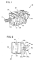
- connector 10 of the shielded type as more particularly shown and described in commonly owned Patent U.S. 4,619,494 as referred to hereinabove.
- connector 10 comprises an insulative housing 12, a front end 12a of which defines a mating end of the connector and a rear end 12b of which is adapted to receive a shielded electrical cable 14 for internal connection to a plurality of electrical contacts ⁇ not shown ⁇ supported interiorly of the housing 12.
- Latching apparatus 15 as will be described in more detail hereinbelow, is incorporated in electrical connector 10. It should be appreciated, however, that the latching apparatus of the subject invention, while particularly useful in the type of electrical connector as shown herein, is not so limited and may be used with other electrical connectors.
- Latching apparatus 15 comprises a relatively rigid, deflectable latching arm 16 that is pivotally mounted on the housing cover 18 and a slidable locking bar 20.
- Housing cover 18 is a portion of the housing and is preferably separable from the remainder of the electrical housing 12 in a manner to facilitate the termination of the electrical cable 14 to the connector contacts supported in the housing.
- the deflectable arm 16 is attached to the cover 18 by a flexible web 22 such that the arm 16 is upwardly spaced from and pivotally movable on the cover 18.
- the deflectable arm 16 is generally elongate, the arm 16 being supported on the cover 18 intermediate its front end 16a and its rear end 16b. As such, both the front end 16a and the rear end 16b of the flexible latching arm are movable generally transversely toward and away from the cover 18 of the electrical connector housing.
- the front end 16a of the arm is particularly configured to provide a latch thereat for mechanical engagement with a complementary latch of another electrical connector or other electrical device.
- Adjacent the front end 16a of the deflectable arm and disposed on its lower surface is a downwardly projecting member defining a locking spacer 24.
- a generally curved recess 26 is formed in the lower surface of the arm 16. The function and purpose of the arm locking spacer 24 and the recess 26 will be described hereinafter.
- the slidable locking bar 20 is relatively rigid and is of generally planar construction. At the rear end of the locking bar there is provided an upwardly extending handle 28 adapted for manual grasping and operation of the latching apparatus by the user. Upwardly extending from the upper surface of the locking bar 20 is a projection defining a bar locking spacer 30, locking spacer 30 being adapted and configured for engagement with the deflectable arm 16. The front end of the locking bar comprises a downwardly tapering surface 32 adapted for engagement with the locking spacer 24 of the deflectable arm 16.
- the locking bar 20 includes at its front end 20a a pair of spaced tines 34 defining a slot 36 therebetween, tines 34 being resiliently laterally deflectable toward and away from each other.
- the bar locking spacer 30 is of two-part construction with a space therebetween.
- Locking bar 20 further includes adjacent its front end 20a a generally curved upwardly extending protrusion 38 disposed on either side of the slot 36.
- the sliding bar 20 is captively supported for sliding, longitudinal movement between the deflectable arm 16 and the housing cover 18.
- the flexible web 22 is of two-part construction with an opening (not shown) therebetween.
- the resiliently deflectable tines are inserted through the opening between the two-parts of the web 22, laterally deflecting the tines until shoulders 34a of each tine pass through the web opening. Shoulders 34a and rear surfaces 20b serve to captivate the sliding bar about the web 22.
- Longitudinal sliding of the locking bar 20 is controlled by guide blocks 35 (see Fig. 1) disposed on the cover 18 and which engage the side, marginal edges of the locking bar during movement.
- the latch provided at the front end 16a of the arm is maintained in a positive locking position thereby preventing inadvertent disconnection during use which could occur due to vibrations and the like.
- the locked position is releasably held by a detent that is provided by the resilient receipt of the top of the bar locking spacer 30 in the arm recess 26. This detent is overcome by manually pulling the locking bar 20, leftwardly in the drawing figures.
- FIGs 4(a) and 4(b) the facilitation of attachment to and detachment from other connectors or electrical components is shown.
- the locking bar 20 has been slid longitudinally rearwardly to its second position. In this position, bar locking spacer 30 has been pulled out from the recess 26 of the deflectable arm 16 and the bar front engagement surface 32 has been separated from the arm locking spacer 24. As such, both the front end 16a and rear end 16b of the deflectable arm 16 are free to move transversely toward and away from the cover 18.
- the protrusion 38 on the locking bar 20 is disposed at a location coincident with the pivot 22. As such, the protrusion 38 will contact the undersurface of the arm in a manner to minimize any loose movement of the locking bar 20 that could result in this position inasmuch as the locking bar is held only at the rear of the connector by the guide blocks 35.
- the subject latching apparatus not only provides for ease of either attaching or detaching an electrical connector to or from a mateable component, but also provides a secured locking arrangement when the connector is attached to another connector or the like. It should be further appreciated that various modifications may be made to the subject latching apparatus without departing from the contemplated scope of the invention. Accordingly, the preferred embodiment described herein is intended in an illustrative rather than a limiting sense. The true scope of the invention is set forth in the claims appended hereto.
Landscapes
- Details Of Connecting Devices For Male And Female Coupling (AREA)
- Connector Housings Or Holding Contact Members (AREA)
Applications Claiming Priority (2)
| Application Number | Priority Date | Filing Date | Title |
|---|---|---|---|
| US07/006,418 US4711511A (en) | 1987-01-23 | 1987-01-23 | Latching apparatus for an electrical connector |
| US6418 | 1987-01-23 |
Publications (3)
| Publication Number | Publication Date |
|---|---|
| EP0276129A2 true EP0276129A2 (fr) | 1988-07-27 |
| EP0276129A3 EP0276129A3 (en) | 1989-04-12 |
| EP0276129B1 EP0276129B1 (fr) | 1994-01-05 |
Family
ID=21720786
Family Applications (1)
| Application Number | Title | Priority Date | Filing Date |
|---|---|---|---|
| EP88300423A Expired - Lifetime EP0276129B1 (fr) | 1987-01-23 | 1988-01-20 | Dispositif d'encliquetage pour un connecteur électrique |
Country Status (6)
| Country | Link |
|---|---|
| US (1) | US4711511A (fr) |
| EP (1) | EP0276129B1 (fr) |
| JP (1) | JPS63218170A (fr) |
| AU (1) | AU591016B2 (fr) |
| CA (1) | CA1307568C (fr) |
| DE (1) | DE3886782T2 (fr) |
Cited By (1)
| Publication number | Priority date | Publication date | Assignee | Title |
|---|---|---|---|---|
| EP0480577A1 (fr) * | 1990-09-28 | 1992-04-15 | The Whitaker Corporation | Mécanisme de verrouillage pour des connecteurs d'informations blindés |
Families Citing this family (36)
| Publication number | Priority date | Publication date | Assignee | Title |
|---|---|---|---|---|
| US4711511A (en) * | 1987-01-23 | 1987-12-08 | Thomas & Betts Corporation | Latching apparatus for an electrical connector |
| JPH0433666Y2 (fr) * | 1988-05-13 | 1992-08-12 | ||
| FR2631749B1 (fr) * | 1988-05-18 | 1991-12-06 | Alsthom Cgee | Module verrouillable pour connecteur |
| IE883885L (en) * | 1988-12-29 | 1990-06-29 | Mcdaid Denis | Telephone lock |
| US5030121A (en) * | 1990-02-13 | 1991-07-09 | Thomas & Betts Corporation | Electrical connector with contact wiping action |
| GB2244181B (en) * | 1990-04-13 | 1994-12-21 | Oki Electric Cable | Double lock male/female type connector |
| US5195902A (en) * | 1990-05-11 | 1993-03-23 | Rit-Rad Interconnection Technologies Ltd. | Electrical connector |
| US5052940A (en) * | 1990-05-11 | 1991-10-01 | Rit-Rad Interconnection Technologies Ltd. | Hermaphroditic self-shorting electrical connector |
| FR2664754B1 (fr) * | 1990-07-11 | 1992-10-16 | Interconnection Inf | Connecteur male pour reseau de communication informatique et/ou telephonique. |
| US5074803A (en) * | 1990-09-28 | 1991-12-24 | Amp Incorporated | Latching mechanism for shielded data connector |
| US5122076A (en) * | 1990-09-28 | 1992-06-16 | Amp Incorporated | Data connector locking mechanism |
| JP2563323Y2 (ja) * | 1990-10-22 | 1998-02-18 | 矢崎総業株式会社 | コネクタ |
| US5112243A (en) * | 1991-02-20 | 1992-05-12 | Chian Chyun Enterprise Co. Ltd. | Latching device for an electrical connector |
| US5405268A (en) * | 1993-02-04 | 1995-04-11 | Thomas & Betts Corporation | Vertically aligned electrical connector components |
| US5376021A (en) * | 1993-02-05 | 1994-12-27 | Thomas & Betts Corporation | Enhanced performance data connector |
| US5593311A (en) * | 1993-07-14 | 1997-01-14 | Thomas & Betts Corporation | Shielded compact data connector |
| DE69415164T2 (de) * | 1994-10-10 | 1999-10-28 | Molex Inc., Lisle | Elektrischer Verbinder mit Lagesicherungssystem. |
| US5628648A (en) * | 1995-03-17 | 1997-05-13 | Molex Incorporated | Electrical connector position assurance system |
| US5643003A (en) * | 1995-06-02 | 1997-07-01 | The Whitaker Corporation | Housing latch with connector position assurance device |
| US5759058A (en) * | 1995-06-06 | 1998-06-02 | Cardell Corporation | Connector position assurance component |
| US5681178A (en) * | 1995-06-27 | 1997-10-28 | The Whitaker Corporation | Electrical connector with connector position assurance device |
| US6004153A (en) * | 1996-03-27 | 1999-12-21 | The Whitaker Corporation | Electrical connector with connector position assurance device |
| US5823813A (en) * | 1997-01-21 | 1998-10-20 | Itt Manufacturing Enterprises, Inc. | Connector position assurance device |
| US6231392B1 (en) | 1997-10-01 | 2001-05-15 | Berg Technology, Inc. | Cable interconnection |
| US6146181A (en) * | 1998-11-16 | 2000-11-14 | Plaza; Aaron M. | Interlocking electrical connector assembly having a guiding member and removal recess |
| US6312277B1 (en) | 1999-01-27 | 2001-11-06 | Cardell Corporation | Connector position assurance device for a connector |
| US6186819B1 (en) | 1999-01-27 | 2001-02-13 | Cardell Corporation | Latching mechanism for a connector |
| USD464318S1 (en) | 2001-03-02 | 2002-10-15 | Smk Corporation | Coaxial connector |
| USD456355S1 (en) | 2001-03-02 | 2002-04-30 | Smk Corporation | Coaxial connector |
| US7492273B2 (en) | 2003-03-10 | 2009-02-17 | Walter Kidde Portable Equipment, Inc. | Pivoting battery carrier and a life safety device incorporating the same |
| US7261575B2 (en) * | 2005-03-09 | 2007-08-28 | Tyco Electronics Corporation | Electrical connector and electrical connector assembly having selectively includable lever assist |
| US7255580B2 (en) * | 2005-03-09 | 2007-08-14 | Tyco Electronics Corporation | Electrical connector and electrical connector assembly having lever assist with latch hold down mechanism |
| US20080050961A1 (en) * | 2006-08-24 | 2008-02-28 | Hon Hai Precision Ind. Co., Ltd. | Electrical connector with improved latching structure |
| DE102007029177A1 (de) * | 2007-06-25 | 2009-01-08 | BSH Bosch und Siemens Hausgeräte GmbH | Kabeldurchführung für ein Kältegerät |
| US7396250B1 (en) * | 2007-07-13 | 2008-07-08 | Kui-Hsien Huang | Plugging device for network cable |
| US9310569B2 (en) * | 2014-02-21 | 2016-04-12 | Alliance Fiber Optic Products, Inc. | Reconfigurable fiber optic adapter |
Family Cites Families (29)
| Publication number | Priority date | Publication date | Assignee | Title |
|---|---|---|---|---|
| US2566993A (en) * | 1948-10-28 | 1951-09-04 | Frederick L Parsons | Electrical connector |
| BE566927A (fr) * | 1957-04-22 | |||
| US3146051A (en) * | 1960-09-12 | 1964-08-25 | Gen Motors Corp | Terminal and mounting means |
| NL300750A (fr) * | 1962-11-28 | |||
| US3207536A (en) * | 1963-03-26 | 1965-09-21 | Deutsch Co | Coupling having pin and finger clamping means with lock |
| US3522963A (en) * | 1967-10-13 | 1970-08-04 | Ind Electronic Eng Inc | Latching mechanism |
| US3523269A (en) * | 1968-03-08 | 1970-08-04 | Essex International Inc | Panel locking terminal connector block |
| FR2072990A5 (fr) * | 1969-12-08 | 1971-09-24 | Yazaki Corp | |
| US3706954A (en) * | 1970-12-28 | 1972-12-19 | Molex Inc | Connector and arrangement for circuit board assembly therewith |
| US3713076A (en) * | 1971-09-30 | 1973-01-23 | Electronic Eng Co | Locking electrical cable connection apparatus |
| GB1413673A (en) * | 1972-06-26 | 1975-11-12 | Bunker Ramo | Push-pull connector |
| CH587571A5 (en) * | 1975-09-08 | 1977-05-13 | Reichle & De Massari Fa | Telephone distributor connector plug - with captive latch and detents for moving from open to locked position |
| CH604388A5 (fr) * | 1975-11-24 | 1978-09-15 | Walter Fischer | |
| US4010998A (en) * | 1976-01-26 | 1977-03-08 | General Motors Corporation | Matable electrical connector means with inertia lock |
| FR2408232A1 (fr) * | 1977-11-04 | 1979-06-01 | Souriau & Cie | Perfectionnements aux dispositifs de connexion |
| US4245879A (en) * | 1978-06-12 | 1981-01-20 | Magnetic Controls Company | Latch assembly |
| JPS5749913Y2 (fr) * | 1979-09-05 | 1982-11-01 | ||
| FR2466884A1 (fr) * | 1979-09-27 | 1981-04-10 | Socapex | Embase de raccordement pour circuits electriques, et circuit muni d'une telle embase |
| US4449767A (en) * | 1982-08-30 | 1984-05-22 | Amp Incorporated | Connector assembly having improved keying and latching system |
| US4448467A (en) * | 1982-09-02 | 1984-05-15 | Amp Incorporated | Connector assembly having compact keying and latching system |
| US4449778A (en) * | 1982-12-22 | 1984-05-22 | Amp Incorporated | Shielded electrical connector |
| US4501459A (en) * | 1982-12-22 | 1985-02-26 | Amp Incorporated | Electrical connector |
| US4508415A (en) * | 1983-07-29 | 1985-04-02 | Amp Incorporated | Shielded electrical connector for flat cable |
| JPS6071084U (ja) * | 1983-10-24 | 1985-05-20 | 星電器製造株式会社 | ロツク機構付コネクタ |
| US4541036A (en) * | 1984-07-06 | 1985-09-10 | General Motors Corporation | Latch for terminal block |
| US4711507A (en) * | 1985-10-07 | 1987-12-08 | Thomas & Betts Corporation | Electrical connector and latching apparatus therefor |
| US4619494A (en) * | 1985-10-07 | 1986-10-28 | Thomas & Betts Corporation | Shielded electrical connector |
| US4634204A (en) * | 1985-12-24 | 1987-01-06 | General Motors Corporation | Electrical connector with connector position assurance/assist device |
| US4711511A (en) * | 1987-01-23 | 1987-12-08 | Thomas & Betts Corporation | Latching apparatus for an electrical connector |
-
1987
- 1987-01-23 US US07/006,418 patent/US4711511A/en not_active Expired - Lifetime
-
1988
- 1988-01-19 AU AU10383/88A patent/AU591016B2/en not_active Ceased
- 1988-01-20 EP EP88300423A patent/EP0276129B1/fr not_active Expired - Lifetime
- 1988-01-20 DE DE88300423T patent/DE3886782T2/de not_active Expired - Fee Related
- 1988-01-20 CA CA000556916A patent/CA1307568C/fr not_active Expired - Lifetime
- 1988-01-22 JP JP63011017A patent/JPS63218170A/ja active Granted
Cited By (1)
| Publication number | Priority date | Publication date | Assignee | Title |
|---|---|---|---|---|
| EP0480577A1 (fr) * | 1990-09-28 | 1992-04-15 | The Whitaker Corporation | Mécanisme de verrouillage pour des connecteurs d'informations blindés |
Also Published As
| Publication number | Publication date |
|---|---|
| DE3886782D1 (de) | 1994-02-17 |
| CA1307568C (fr) | 1992-09-15 |
| JPS63218170A (ja) | 1988-09-12 |
| AU1038388A (en) | 1988-07-28 |
| DE3886782T2 (de) | 1994-04-28 |
| EP0276129B1 (fr) | 1994-01-05 |
| AU591016B2 (en) | 1989-11-23 |
| JPH0337267B2 (fr) | 1991-06-05 |
| US4711511A (en) | 1987-12-08 |
| EP0276129A3 (en) | 1989-04-12 |
Similar Documents
| Publication | Publication Date | Title |
|---|---|---|
| US4711511A (en) | Latching apparatus for an electrical connector | |
| US4711507A (en) | Electrical connector and latching apparatus therefor | |
| EP0734599B1 (fr) | Ensemble connecteur pour carte a circuit integre | |
| KR0146975B1 (ko) | 전기 커넥터 | |
| JP2787307B2 (ja) | コネクタ | |
| EP0116426B1 (fr) | Ensemble de connecteur électrique comprenant une barre d'éjection | |
| US4232926A (en) | Locking mechanism for coupling and uncoupling electrical connectors | |
| EP1100160B1 (fr) | Ensemble d'un connecteur électrique avec un système de came améliorée | |
| JPS61176082A (ja) | 電気コネクタ | |
| EP0929125A2 (fr) | Verrouillage de connecteur avec charnière de forme tubulaire | |
| WO1993003516A1 (fr) | Connecteur verrouillable pour plaquette de circuits imprimes | |
| US5425169A (en) | Backplane removal and insertion tool | |
| JPH04109573A (ja) | 電気コネクタ及びその製造方法 | |
| US5112243A (en) | Latching device for an electrical connector | |
| EP0356157A2 (fr) | Connecteur électrique ayant un loquet antisurcharge | |
| US4647129A (en) | Electrical connector | |
| GB2166300A (en) | Electrical connector assembly | |
| EP2240983B1 (fr) | Verrouillage de réceptacles électriques | |
| US4447102A (en) | Electrical connector assemblies | |
| US5108306A (en) | Method and apparatus for providing cable strain relief in an electrical connector assembly | |
| US10873157B1 (en) | Pull tab for a plug connector | |
| US20020155746A1 (en) | Cable assembly latch | |
| US4679869A (en) | Cable connector holder | |
| US12051866B2 (en) | Electrical connector assembly | |
| JPS6011569Y2 (ja) | 平形ケ−ブル用コネクタ |
Legal Events
| Date | Code | Title | Description |
|---|---|---|---|
| PUAI | Public reference made under article 153(3) epc to a published international application that has entered the european phase |
Free format text: ORIGINAL CODE: 0009012 |
|
| AK | Designated contracting states |
Kind code of ref document: A2 Designated state(s): BE CH DE FR GB IT LI NL SE |
|
| PUAL | Search report despatched |
Free format text: ORIGINAL CODE: 0009013 |
|
| RHK1 | Main classification (correction) |
Ipc: H01R 13/639 |
|
| AK | Designated contracting states |
Kind code of ref document: A3 Designated state(s): BE CH DE FR GB IT LI NL SE |
|
| RAP3 | Party data changed (applicant data changed or rights of an application transferred) |
Owner name: THOMAS & BETTS CORPORATION |
|
| 17P | Request for examination filed |
Effective date: 19890918 |
|
| 17Q | First examination report despatched |
Effective date: 19911119 |
|
| GRAA | (expected) grant |
Free format text: ORIGINAL CODE: 0009210 |
|
| AK | Designated contracting states |
Kind code of ref document: B1 Designated state(s): BE CH DE FR GB IT LI NL SE |
|
| REF | Corresponds to: |
Ref document number: 3886782 Country of ref document: DE Date of ref document: 19940217 |
|
| ET | Fr: translation filed | ||
| ITF | It: translation for a ep patent filed | ||
| REG | Reference to a national code |
Ref country code: CH Ref legal event code: PFA Free format text: THOMAS & BETTS CORPORATION |
|
| RAP4 | Party data changed (patent owner data changed or rights of a patent transferred) |
Owner name: THOMAS & BETTS CORPORATION |
|
| PLBE | No opposition filed within time limit |
Free format text: ORIGINAL CODE: 0009261 |
|
| STAA | Information on the status of an ep patent application or granted ep patent |
Free format text: STATUS: NO OPPOSITION FILED WITHIN TIME LIMIT |
|
| 26N | No opposition filed | ||
| EAL | Se: european patent in force in sweden |
Ref document number: 88300423.6 |
|
| REG | Reference to a national code |
Ref country code: FR Ref legal event code: TP Ref country code: FR Ref legal event code: CA |
|
| REG | Reference to a national code |
Ref country code: CH Ref legal event code: PUE Owner name: THOMAS & BETTS CORPORATION TRANSFER- THOMAS & BETT |
|
| REG | Reference to a national code |
Ref country code: GB Ref legal event code: 732E |
|
| REG | Reference to a national code |
Ref country code: GB Ref legal event code: IF02 |
|
| PGFP | Annual fee paid to national office [announced via postgrant information from national office to epo] |
Ref country code: SE Payment date: 20020103 Year of fee payment: 15 Ref country code: FR Payment date: 20020103 Year of fee payment: 15 Ref country code: DE Payment date: 20020103 Year of fee payment: 15 |
|
| PGFP | Annual fee paid to national office [announced via postgrant information from national office to epo] |
Ref country code: GB Payment date: 20020104 Year of fee payment: 15 |
|
| PGFP | Annual fee paid to national office [announced via postgrant information from national office to epo] |
Ref country code: NL Payment date: 20020107 Year of fee payment: 15 Ref country code: CH Payment date: 20020107 Year of fee payment: 15 |
|
| PGFP | Annual fee paid to national office [announced via postgrant information from national office to epo] |
Ref country code: BE Payment date: 20020124 Year of fee payment: 15 |
|
| PG25 | Lapsed in a contracting state [announced via postgrant information from national office to epo] |
Ref country code: GB Free format text: LAPSE BECAUSE OF NON-PAYMENT OF DUE FEES Effective date: 20030120 |
|
| PG25 | Lapsed in a contracting state [announced via postgrant information from national office to epo] |
Ref country code: SE Free format text: LAPSE BECAUSE OF NON-PAYMENT OF DUE FEES Effective date: 20030121 |
|
| PG25 | Lapsed in a contracting state [announced via postgrant information from national office to epo] |
Ref country code: LI Free format text: LAPSE BECAUSE OF NON-PAYMENT OF DUE FEES Effective date: 20030131 Ref country code: CH Free format text: LAPSE BECAUSE OF NON-PAYMENT OF DUE FEES Effective date: 20030131 Ref country code: BE Free format text: LAPSE BECAUSE OF NON-PAYMENT OF DUE FEES Effective date: 20030131 |
|
| PG25 | Lapsed in a contracting state [announced via postgrant information from national office to epo] |
Ref country code: NL Free format text: LAPSE BECAUSE OF NON-PAYMENT OF DUE FEES Effective date: 20030801 Ref country code: DE Free format text: LAPSE BECAUSE OF NON-PAYMENT OF DUE FEES Effective date: 20030801 |
|
| EUG | Se: european patent has lapsed | ||
| GBPC | Gb: european patent ceased through non-payment of renewal fee | ||
| REG | Reference to a national code |
Ref country code: CH Ref legal event code: PL |
|
| PG25 | Lapsed in a contracting state [announced via postgrant information from national office to epo] |
Ref country code: FR Free format text: LAPSE BECAUSE OF NON-PAYMENT OF DUE FEES Effective date: 20030930 |
|
| NLV4 | Nl: lapsed or anulled due to non-payment of the annual fee |
Effective date: 20030801 |
|
| REG | Reference to a national code |
Ref country code: FR Ref legal event code: ST |
|
| PG25 | Lapsed in a contracting state [announced via postgrant information from national office to epo] |
Ref country code: IT Free format text: LAPSE BECAUSE OF NON-PAYMENT OF DUE FEES;WARNING: LAPSES OF ITALIAN PATENTS WITH EFFECTIVE DATE BEFORE 2007 MAY HAVE OCCURRED AT ANY TIME BEFORE 2007. THE CORRECT EFFECTIVE DATE MAY BE DIFFERENT FROM THE ONE RECORDED. Effective date: 20050120 |