EP0480577A1 - Mécanisme de verrouillage pour des connecteurs d'informations blindés - Google Patents
Mécanisme de verrouillage pour des connecteurs d'informations blindés Download PDFInfo
- Publication number
- EP0480577A1 EP0480577A1 EP91308168A EP91308168A EP0480577A1 EP 0480577 A1 EP0480577 A1 EP 0480577A1 EP 91308168 A EP91308168 A EP 91308168A EP 91308168 A EP91308168 A EP 91308168A EP 0480577 A1 EP0480577 A1 EP 0480577A1
- Authority
- EP
- European Patent Office
- Prior art keywords
- housing
- latching
- locking ring
- latching members
- electrical connector
- Prior art date
- Legal status (The legal status is an assumption and is not a legal conclusion. Google has not performed a legal analysis and makes no representation as to the accuracy of the status listed.)
- Granted
Links
- 230000007246 mechanism Effects 0.000 title claims description 7
- 230000013011 mating Effects 0.000 claims abstract description 12
- 230000000295 complement effect Effects 0.000 claims description 2
- 239000000463 material Substances 0.000 claims description 2
- 230000014759 maintenance of location Effects 0.000 description 16
- 239000004020 conductor Substances 0.000 description 3
- 238000006073 displacement reaction Methods 0.000 description 1
- 238000009413 insulation Methods 0.000 description 1
- 230000000717 retained effect Effects 0.000 description 1
- 239000011800 void material Substances 0.000 description 1
Images



Classifications
-
- H—ELECTRICITY
- H01—ELECTRIC ELEMENTS
- H01R—ELECTRICALLY-CONDUCTIVE CONNECTIONS; STRUCTURAL ASSOCIATIONS OF A PLURALITY OF MUTUALLY-INSULATED ELECTRICAL CONNECTING ELEMENTS; COUPLING DEVICES; CURRENT COLLECTORS
- H01R13/00—Details of coupling devices of the kinds covered by groups H01R12/70 or H01R24/00 - H01R33/00
- H01R13/62—Means for facilitating engagement or disengagement of coupling parts or for holding them in engagement
- H01R13/639—Additional means for holding or locking coupling parts together, after engagement, e.g. separate keylock, retainer strap
-
- H—ELECTRICITY
- H01—ELECTRIC ELEMENTS
- H01R—ELECTRICALLY-CONDUCTIVE CONNECTIONS; STRUCTURAL ASSOCIATIONS OF A PLURALITY OF MUTUALLY-INSULATED ELECTRICAL CONNECTING ELEMENTS; COUPLING DEVICES; CURRENT COLLECTORS
- H01R13/00—Details of coupling devices of the kinds covered by groups H01R12/70 or H01R24/00 - H01R33/00
- H01R13/62—Means for facilitating engagement or disengagement of coupling parts or for holding them in engagement
- H01R13/627—Snap or like fastening
- H01R13/6275—Latching arms not integral with the housing
-
- H—ELECTRICITY
- H01—ELECTRIC ELEMENTS
- H01R—ELECTRICALLY-CONDUCTIVE CONNECTIONS; STRUCTURAL ASSOCIATIONS OF A PLURALITY OF MUTUALLY-INSULATED ELECTRICAL CONNECTING ELEMENTS; COUPLING DEVICES; CURRENT COLLECTORS
- H01R13/00—Details of coupling devices of the kinds covered by groups H01R12/70 or H01R24/00 - H01R33/00
- H01R13/62—Means for facilitating engagement or disengagement of coupling parts or for holding them in engagement
- H01R13/627—Snap or like fastening
Definitions
- This invention relates to electrical connectors for use in terminating shielded multiconductor cables and more specifically to a data connector having a slidable retention member for locking the data connector in a latched configuration.
- U.S. Patent No. RE32,760 discloses a local area network connector specifically intended for use in the data communications industry. These connectors can be employed in a closed loop data communications link in which various equipment, such as computer terminals, can be interconnected in a system. These connectors are specifically adapted for use in interconnecting numerous micro- or mini-computers in a computer network in an office environment. Connectors of this type have standard interface dimensions and configurations.
- U.S. Patent 4,884,981 addresses a need within the local area network market for a lower cost and more versatile electrical connector which is suitable for use in a local area network in combination with prior art connectors of the type described herein.
- the electrical connector shown in U.S. Patent 4,884,981 includes a shielded subassembly positioned within a one piece molded housing, where the one piece housing has a common interface structure as the prior art connectors.
- a discrete locking member is available which is movable laterally between the latching arms and the top of the housing, filling the void between the latching arms and the housing on both sides of the integral web forming the hinge, thereby preventing the pivotal movement of the latching arms while the locking member is in place.
- each latching arm includes a locking bar between the pivotal arm and the housing and is longitudinally movable to perform a wedgelike function thereby preventing the pivotal movement of the latching arms when the locking bars are in the fully forward position.
- an electrical connector comprising an insulative housing having a mating face and a wire connecting face.
- Latching members are provided which are integrally connected to the opposite side surfaces of the housing, the latching members being integrally connected via molded webs of material medially positioned between ends of the latching members where one end of each latching member has a latching mechanism thereon for mating with a complementary electrical connector while opposite ends of the latching members are free to move upwardly and downwardly during the pivoting of the latching members.
- a locking ring peripherally surrounds the insulative housing and is movable longitudinally relative thereto between a locked and unlocked position.
- the locking ring has integral elongate channels adapted to encompass the free ends of the latching member when the locking ring is in the locked position thereby preventing the pivotal movement of the latching members, and the locking ring is movable to an unlocked position with the free ends of the latching members spaced from the channels and free to rotate about the webs.
- the locking ring when in the locked position, prevents the pivotal movement of the latching mechanisms.
- the data connector is generally shown at 2 comprising a shielded subassembly 3 and a premolded boot housing 4, the shielded subassembly 3 being slidably receivable into and out of the premolded boot housing 4 and being latchably attached therein.
- the shielded subassembly 3 and the premolded boot housing 4 are of the type generally shown in U.S. Patent 4,884,981.
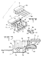
- the shielded subassembly 3 generally includes a housing member 5, a stuffer cap 6, and shield members 7 and 8. With reference now to Figures 1-3, the data connector housing 5 will be described in greater detail.
- the housing 5 generally comprises a terminal support floor 10 having a plurality of channels 12 therein for receiving terminals 13. Extending from the terminal support floor 10 are side walls 14 having internal grooves 15 and external ribs 16. A portion 17 extends across the two side walls and together with the front edges 18 define a front mating face for the housing member 5.
- Terminals 13 include insulation displacement wire barrels 32, a blade portion 34, a resilient contact portion 36 and a commoning foot 38.
- the resilient contact portion 36 is reversely bent upon itself and spaced above the terminal support floor 10.
- the resilient contact portion 36 is disposed at the front mating face of the housing 5 for overlapping interconnection with like terminals, the two resilient contact portions of mating connectors contacting each other to deflect respective resilient contact portions towards the blade portion of the respective terminals.
- Stuffer cap 6 includes alignment ribs 52 along the sides, wire receiving slots 54 and a lower surface 56 having stuffer cylinders 58 therein, where the stuffer cylinders have an inside diameter larger than the outside diameter of the barrels 32 of the terminals 13, as seen best in Figure 1.
- the shield member 7 includes a plate member 72 with continuous shield members 90 extending from the plate member 72 through a stepped portion 92, the two shield members 90 defining a slot 94 therebetween.
- the plate member 72 further includes two locking lances 77 for locking the shielded subassembly within the boot housing 4.
- the shield member 7 is shown in Figure 3 as including a semicircular shielding tail 76 extending from a rear wall 78.
- the shield member 7 includes integral side walls 80 having windows 84 stamped therefrom (only one window is visible in Figure 1). The forward edges of the side walls are defined by two 45 surfaces 82.
- Shield member 8 is shown as including a plate member 102 with integral shielding portions 110 extending from the front edge thereof, the two shield members 110 defining a slot 112 therebetween.
- the shield member 8 further includes a rear wall portion 114 having a semicircular shield tail 116 extending from the rear wall 114.
- Plate member 102 further comprises locking lances 106 and tabs 104 and 108 extending from the side edges thereof.
- the premolded boot housing 4 includes a central body portion 122, a flexible wire receiving portion 124 and two latch members 126.
- the two latch members 126 are integrally molded to the central body portion 122 and are pivotal relative to the central body portion about integral hinges shown at 128.
- the latching members 126 are hermaphroditic, where the front edge of one of the latch members includes a T-bar 130, whereas the other latch member includes a C-slot 132.
- two of the housing premolded boots are interconnectable when one of the connector boots is rotated about an axial centerline 180 relative to the other of the housing boots 4, such that a T-bar 130 mates with a C-slot 132 on a mating connector and the C-slot 132 mates with a T-bar 130 on the mating connector.
- the latch members 126 on one of the connectors are moved so as to move the T-bar and C-slot towards each other while the latch members on the mating connector are moved away from each other. Movement of the two housings towards each other places the respective T-bars and C-slots in overlapping latching relation one to the other.
- the premolded boot housing 4 further comprises a forward passageway 134 comprised of upper and lower surfaces 136 and side walls 138, where each of the side walls 138 includes an aperture 140 therethrough.
- the upper and lower surfaces 136 and side walls 138 terminate in a rear edge 142, which then communicates with a cavity 144, and thereafter a cable receiving bore 146.
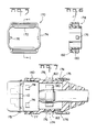
- the premolded boot housing 4 comprises side walls 152 and end walls 154 (only one of which is shown in Figure 4).
- the end walls 154 include a longitudinal slot 156 therein having an integral latch 158 having a forwardly facing latch surface 160.
- the longitudinal slot 156 further comprises a detent 162 integrally molded within the slot 156, and spaced forwardly of the latch 158.
- the connector assembly further comprises a slidable retention member or locking ring 170, having side walls 172 and end walls 174 where the side walls 172 are slidably engageable against the side walls 152 of the premolded boot housing 4 and the end walls 174 are slidably engageable against the end walls 154.
- the end walls 174 include locking lugs 176 on inner surfaces thereof which are receivable in the slots 156 and guide the retention member along a longitudinal path.
- the latch 158 is of the type having a ramped surface increasing in height from the rear towards the front, such that when the lugs 176 pass the latches 158, the lug 176 is in latched engagement against the forwardly facing latch surface 160.
- the latching member 170 further comprises channels 178 defining a locking enclosure which encompasses the free ends of the latch members.
- Each channel 178 has a ramped surface 180 converging inwardly from front to rear and terminating in a narrow slot 182.
- the slots 182 define support steps 183 extending across the locking member 170, and are adapted for receipt beneath the free ends of the latching members.
- the connector is assembled by sliding the terminals 13 into respective channels 12, and by inserting shorting bars 60 in respective grooves 23, as shown in Figure 2.
- the shorting bars contact the commoning foot 38 on alternate terminals to common alternate terminals when the data connector is unmated.
- the multiconductor cable 180 ( Figure 1) is then slid through the opening 146 of the boot, and the boot housing 4 is slid back upon the cable 180.
- the shielded cable is then stripped to access the shielding braid 184 and the individual conductors 186 of the multiconductor cable.
- the individual conductors are placed in slots 54 of the stuffer cap 6 and the stuffer cap 6 is inserted into the housing with the ribs 52 aligned with slots 15 within the housing.
- the stuffer cap inserts the wires into individual terminals 13 with a conductor terminated within the barrel portion 32 of the terminal 13.
- the shield members 7 and 8 are then assembled around the insulative housing 5 such that the slots 84 of the shield member 7 overlap the outside ribs 20, and the side tabs 104 of the shield member 8 are locked in place within the stamped windows 86 of the shield member 7. This places the shielding extensions 76 and 116 in an overlapping relation over the dressed braid 184.
- a collapsible ferrule 190 ( Figure 1) can be crimped in place which electrically interconnects the shield members 7 and 8 to the shielding braid 184 and mechanically retains the shielded subassembly 3 to the multiconductor shielded cable 180.
- the previously inserted premolded boot housing 4 may now be slid forward until the windows 140 in the housing 4 are latched in place with the tabs 77, as shown in Figure 7.
- the slidable retention member 170 can be assembled to the boot housing, either prior to or subsequent to the assembly of the shielded subassembly 3. As shown in Figure 7, the slidable retention member 170 is slidable between positions where the detent member 176 abuts the forwardly facing latch 158, as shown in Figures 4 and 7, to a position beyond the detent member 162 as shown in Figure 7. The movement of the slidable retention member 170 between the positions shown in Figure 7 corresponds to the movement of the retention member 170 between the positions shown in Figures 8 and 9.
- the upper and lower latch members 126 are free to pivot about their integral hinge member 128 for latching and unlatching of the mateable electrical connectors.
- the ends of the latch members 126 are positioned in the transverse grooves 182 of the retention member 170.
- the ramp surface 180 also assists the end 129 of the latch member 126 for alignment with the transverse groove 182.
Landscapes
- Details Of Connecting Devices For Male And Female Coupling (AREA)
Applications Claiming Priority (2)
| Application Number | Priority Date | Filing Date | Title |
|---|---|---|---|
| US59063690A | 1990-09-28 | 1990-09-28 | |
| US590636 | 1990-09-28 |
Publications (2)
| Publication Number | Publication Date |
|---|---|
| EP0480577A1 true EP0480577A1 (fr) | 1992-04-15 |
| EP0480577B1 EP0480577B1 (fr) | 1995-12-06 |
Family
ID=24363022
Family Applications (1)
| Application Number | Title | Priority Date | Filing Date |
|---|---|---|---|
| EP91308168A Expired - Lifetime EP0480577B1 (fr) | 1990-09-28 | 1991-09-06 | Mécanisme de verrouillage pour des connecteurs d'informations blindés |
Country Status (3)
| Country | Link |
|---|---|
| EP (1) | EP0480577B1 (fr) |
| KR (1) | KR970004149B1 (fr) |
| DE (1) | DE69115216T2 (fr) |
Cited By (1)
| Publication number | Priority date | Publication date | Assignee | Title |
|---|---|---|---|---|
| EP1970999A1 (fr) | 2007-03-14 | 2008-09-17 | Yamaichi Electronics Deutschland GmbH | Décharge de traction |
Citations (2)
| Publication number | Priority date | Publication date | Assignee | Title |
|---|---|---|---|---|
| GB2153161A (en) * | 1984-01-20 | 1985-08-14 | Emi Ltd | Locking latch retainer of two- part electrical connector |
| EP0276129A2 (fr) * | 1987-01-23 | 1988-07-27 | THOMAS & BETTS CORPORATION | Dispositif d'encliquetage pour un connecteur électrique |
-
1991
- 1991-09-06 DE DE69115216T patent/DE69115216T2/de not_active Expired - Fee Related
- 1991-09-06 EP EP91308168A patent/EP0480577B1/fr not_active Expired - Lifetime
- 1991-09-19 KR KR1019910016354A patent/KR970004149B1/ko not_active Expired - Fee Related
Patent Citations (2)
| Publication number | Priority date | Publication date | Assignee | Title |
|---|---|---|---|---|
| GB2153161A (en) * | 1984-01-20 | 1985-08-14 | Emi Ltd | Locking latch retainer of two- part electrical connector |
| EP0276129A2 (fr) * | 1987-01-23 | 1988-07-27 | THOMAS & BETTS CORPORATION | Dispositif d'encliquetage pour un connecteur électrique |
Cited By (1)
| Publication number | Priority date | Publication date | Assignee | Title |
|---|---|---|---|---|
| EP1970999A1 (fr) | 2007-03-14 | 2008-09-17 | Yamaichi Electronics Deutschland GmbH | Décharge de traction |
Also Published As
| Publication number | Publication date |
|---|---|
| DE69115216D1 (de) | 1996-01-18 |
| DE69115216T2 (de) | 1996-07-04 |
| EP0480577B1 (fr) | 1995-12-06 |
| KR970004149B1 (ko) | 1997-03-25 |
| KR920007271A (ko) | 1992-04-28 |
Similar Documents
| Publication | Publication Date | Title |
|---|---|---|
| US5074803A (en) | Latching mechanism for shielded data connector | |
| US5586911A (en) | Shielding data connector | |
| US4891022A (en) | Shielded data connector | |
| US4859201A (en) | Data communications outlet | |
| US6287149B1 (en) | Electrical connector having an improved connector shield and a multi-purpose strain relief | |
| KR930003562B1 (ko) | 시일드 데이타 코넥터 | |
| EP0220018B1 (fr) | Connecteur électrique blindé | |
| EP0351083B1 (fr) | Connecteur électrique | |
| US5052940A (en) | Hermaphroditic self-shorting electrical connector | |
| US4653825A (en) | Shielded electrical connector assembly | |
| EP0233397B1 (fr) | Connecteur électrique et dispositif d'encliquetage pour celui-ci | |
| US5435744A (en) | Sliding boot assembly for electrical connector | |
| EP0219304B1 (fr) | Connecteur électrique et pièce terminale de câble pour celui-ci | |
| US4491381A (en) | Electrical panelboard connector | |
| EP0573126B1 (fr) | Connecteur blindé pour transmissions de données | |
| EP0558250B1 (fr) | Connecteur blindé pour données | |
| US4883433A (en) | Electrical connector for data distribution panel | |
| EP0956619B1 (fr) | Connecteur electrique possedant un blindage ameliore et un serre-cable polyvalent | |
| EP0865113B1 (fr) | Connecteur blindé pour transmissions de données | |
| US5057032A (en) | Board edge connector | |
| EP0480577B1 (fr) | Mécanisme de verrouillage pour des connecteurs d'informations blindés | |
| JP3118903B2 (ja) | データコネクタ | |
| JPH0415588B2 (fr) |
Legal Events
| Date | Code | Title | Description |
|---|---|---|---|
| PUAI | Public reference made under article 153(3) epc to a published international application that has entered the european phase |
Free format text: ORIGINAL CODE: 0009012 |
|
| AK | Designated contracting states |
Kind code of ref document: A1 Designated state(s): DE FR GB IT NL |
|
| 17P | Request for examination filed |
Effective date: 19920731 |
|
| RAP1 | Party data changed (applicant data changed or rights of an application transferred) |
Owner name: THE WHITAKER CORPORATION |
|
| 17Q | First examination report despatched |
Effective date: 19940816 |
|
| GRAA | (expected) grant |
Free format text: ORIGINAL CODE: 0009210 |
|
| AK | Designated contracting states |
Kind code of ref document: B1 Designated state(s): DE FR GB IT NL |
|
| ITF | It: translation for a ep patent filed | ||
| REF | Corresponds to: |
Ref document number: 69115216 Country of ref document: DE Date of ref document: 19960118 |
|
| ET | Fr: translation filed | ||
| PLBE | No opposition filed within time limit |
Free format text: ORIGINAL CODE: 0009261 |
|
| STAA | Information on the status of an ep patent application or granted ep patent |
Free format text: STATUS: NO OPPOSITION FILED WITHIN TIME LIMIT |
|
| 26N | No opposition filed | ||
| PGFP | Annual fee paid to national office [announced via postgrant information from national office to epo] |
Ref country code: NL Payment date: 19990630 Year of fee payment: 9 |
|
| PG25 | Lapsed in a contracting state [announced via postgrant information from national office to epo] |
Ref country code: NL Free format text: LAPSE BECAUSE OF NON-PAYMENT OF DUE FEES Effective date: 20010401 |
|
| NLV4 | Nl: lapsed or anulled due to non-payment of the annual fee |
Effective date: 20010401 |
|
| PGFP | Annual fee paid to national office [announced via postgrant information from national office to epo] |
Ref country code: GB Payment date: 20010807 Year of fee payment: 11 |
|
| PGFP | Annual fee paid to national office [announced via postgrant information from national office to epo] |
Ref country code: FR Payment date: 20010831 Year of fee payment: 11 |
|
| PGFP | Annual fee paid to national office [announced via postgrant information from national office to epo] |
Ref country code: DE Payment date: 20010927 Year of fee payment: 11 |
|
| REG | Reference to a national code |
Ref country code: GB Ref legal event code: IF02 |
|
| PG25 | Lapsed in a contracting state [announced via postgrant information from national office to epo] |
Ref country code: GB Free format text: LAPSE BECAUSE OF NON-PAYMENT OF DUE FEES Effective date: 20020906 |
|
| PG25 | Lapsed in a contracting state [announced via postgrant information from national office to epo] |
Ref country code: DE Free format text: LAPSE BECAUSE OF NON-PAYMENT OF DUE FEES Effective date: 20030401 |
|
| GBPC | Gb: european patent ceased through non-payment of renewal fee |
Effective date: 20020906 |
|
| PG25 | Lapsed in a contracting state [announced via postgrant information from national office to epo] |
Ref country code: FR Free format text: LAPSE BECAUSE OF NON-PAYMENT OF DUE FEES Effective date: 20030603 |
|
| REG | Reference to a national code |
Ref country code: FR Ref legal event code: ST |
|
| PG25 | Lapsed in a contracting state [announced via postgrant information from national office to epo] |
Ref country code: IT Free format text: LAPSE BECAUSE OF NON-PAYMENT OF DUE FEES;WARNING: LAPSES OF ITALIAN PATENTS WITH EFFECTIVE DATE BEFORE 2007 MAY HAVE OCCURRED AT ANY TIME BEFORE 2007. THE CORRECT EFFECTIVE DATE MAY BE DIFFERENT FROM THE ONE RECORDED. Effective date: 20050906 |