EP0276351B1 - Dichtungseinrichtung für Elektrolysezelle - Google Patents
Dichtungseinrichtung für Elektrolysezelle Download PDFInfo
- Publication number
- EP0276351B1 EP0276351B1 EP87101207A EP87101207A EP0276351B1 EP 0276351 B1 EP0276351 B1 EP 0276351B1 EP 87101207 A EP87101207 A EP 87101207A EP 87101207 A EP87101207 A EP 87101207A EP 0276351 B1 EP0276351 B1 EP 0276351B1
- Authority
- EP
- European Patent Office
- Prior art keywords
- seal means
- separator
- side wall
- cell
- electrode frame
- Prior art date
- Legal status (The legal status is an assumption and is not a legal conclusion. Google has not performed a legal analysis and makes no representation as to the accuracy of the status listed.)
- Expired
Links
Images


Classifications
-
- F—MECHANICAL ENGINEERING; LIGHTING; HEATING; WEAPONS; BLASTING
- F16—ENGINEERING ELEMENTS AND UNITS; GENERAL MEASURES FOR PRODUCING AND MAINTAINING EFFECTIVE FUNCTIONING OF MACHINES OR INSTALLATIONS; THERMAL INSULATION IN GENERAL
- F16J—PISTONS; CYLINDERS; SEALINGS
- F16J15/00—Sealings
- F16J15/02—Sealings between relatively-stationary surfaces
- F16J15/06—Sealings between relatively-stationary surfaces with solid packing compressed between sealing surfaces
- F16J15/10—Sealings between relatively-stationary surfaces with solid packing compressed between sealing surfaces with non-metallic packing
- F16J15/104—Sealings between relatively-stationary surfaces with solid packing compressed between sealing surfaces with non-metallic packing characterised by structure
- F16J15/106—Sealings between relatively-stationary surfaces with solid packing compressed between sealing surfaces with non-metallic packing characterised by structure homogeneous
-
- C—CHEMISTRY; METALLURGY
- C25—ELECTROLYTIC OR ELECTROPHORETIC PROCESSES; APPARATUS THEREFOR
- C25B—ELECTROLYTIC OR ELECTROPHORETIC PROCESSES FOR THE PRODUCTION OF COMPOUNDS OR NON-METALS; APPARATUS THEREFOR
- C25B9/00—Cells or assemblies of cells; Constructional parts of cells; Assemblies of constructional parts, e.g. electrode-diaphragm assemblies; Process-related cell features
-
- C—CHEMISTRY; METALLURGY
- C25—ELECTROLYTIC OR ELECTROPHORETIC PROCESSES; APPARATUS THEREFOR
- C25B—ELECTROLYTIC OR ELECTROPHORETIC PROCESSES FOR THE PRODUCTION OF COMPOUNDS OR NON-METALS; APPARATUS THEREFOR
- C25B9/00—Cells or assemblies of cells; Constructional parts of cells; Assemblies of constructional parts, e.g. electrode-diaphragm assemblies; Process-related cell features
- C25B9/60—Constructional parts of cells
-
- C—CHEMISTRY; METALLURGY
- C25—ELECTROLYTIC OR ELECTROPHORETIC PROCESSES; APPARATUS THEREFOR
- C25B—ELECTROLYTIC OR ELECTROPHORETIC PROCESSES FOR THE PRODUCTION OF COMPOUNDS OR NON-METALS; APPARATUS THEREFOR
- C25B9/00—Cells or assemblies of cells; Constructional parts of cells; Assemblies of constructional parts, e.g. electrode-diaphragm assemblies; Process-related cell features
- C25B9/70—Assemblies comprising two or more cells
- C25B9/73—Assemblies comprising two or more cells of the filter-press type
-
- C—CHEMISTRY; METALLURGY
- C25—ELECTROLYTIC OR ELECTROPHORETIC PROCESSES; APPARATUS THEREFOR
- C25B—ELECTROLYTIC OR ELECTROPHORETIC PROCESSES FOR THE PRODUCTION OF COMPOUNDS OR NON-METALS; APPARATUS THEREFOR
- C25B9/00—Cells or assemblies of cells; Constructional parts of cells; Assemblies of constructional parts, e.g. electrode-diaphragm assemblies; Process-related cell features
- C25B9/70—Assemblies comprising two or more cells
- C25B9/73—Assemblies comprising two or more cells of the filter-press type
- C25B9/77—Assemblies comprising two or more cells of the filter-press type having diaphragms
-
- F—MECHANICAL ENGINEERING; LIGHTING; HEATING; WEAPONS; BLASTING
- F16—ENGINEERING ELEMENTS AND UNITS; GENERAL MEASURES FOR PRODUCING AND MAINTAINING EFFECTIVE FUNCTIONING OF MACHINES OR INSTALLATIONS; THERMAL INSULATION IN GENERAL
- F16J—PISTONS; CYLINDERS; SEALINGS
- F16J15/00—Sealings
- F16J15/02—Sealings between relatively-stationary surfaces
- F16J15/021—Sealings between relatively-stationary surfaces with elastic packing
- F16J15/022—Sealings between relatively-stationary surfaces with elastic packing characterised by structure or material
- F16J15/024—Sealings between relatively-stationary surfaces with elastic packing characterised by structure or material the packing being locally weakened in order to increase elasticity
Definitions
- This invention relates to a seal means for electrolysis cells, a method of sealing electrolysis cells and a cell assembly comprising said seal means.
- Electrolysis cells are used in various applications, for example, electrolyzing an alkali metal salt, such as sodium chloride, to produce a halide and alkali metal hydroxide, such as chlorine and sodium hydroxide.
- alkali metal salt such as sodium chloride
- alkali metal hydroxide such as chlorine and sodium hydroxide
- a typical structure for an electrolysis cell is that of the filter press-type, which includes monopolar or bipolar structures.
- Bipolar structures for example, are as described in U.S. Patent Nos. 4,108,742 and 4,111,779.
- a seal means for an electrolysis cell in particular a filter press-type cell is well known in the art and includes a gasket placed between two adjacent electrode frame members to form an electrolysis cell assembly.
- a compressive force is applied to the entire cell assembly to squeeze the elements together to form a fluid-tight, i.e., liquid- and gas-tight, seal.
- the compressive force typically is applied manually or may be applied utilizing hydraulic rams or other types of pressure-applying apparatus to compress the electrode frame members and gasket together.
- gasket material such as rubber or elastomer to deform and expand outwardly or "ooze-out" of the electrolysis cell assembly as pressure is applied to the frames via the frame members.
- Gaps between cell frame members, caused by gasket oozing out, may lead to gas or electrolyte leakage especially in pressurized cells, requiring shutdown of the cell's operation.
- certain separators which are in contact with the gaskets tend to stretch when they are pulled under the pressure of the outwardly deforming gaskets.
- the stretching of the separator by gasket deformation can cause the separator, which typically is a flat, thin, sheet-like membrane, to break or tear during compression of the gasket and frame members.
- Any tears or breaks in the membrane employed in a cell may lead to reduced current efficiency during operation of the cell, greatly increasing electrical current usage while reducing the electrolytic operating efficiency of the cell. Too great a drop in current efficiency and/or electrolytic operating efficiency can require costly shutdown of the entire cell while the damaged membrane or membranes are replaced.
- EP-A 51360 a sealing means for filter press cells is described which are disposed between two frame members housing an electrode with a separator positioned between said frames whereby the first sealing means is positioned between the first frame and one side of the separator and the second sealing means is positioned between the second frame member and the opposite side of the separator.
- Said second sealing means is constucted that way that it has a raised portion which raised portion contacts the other side of the separator and thereby presses the separator against the first sealing means so as to form a substantially fluid-tight seal.
- JP-A-6156 290 describes a method for attaching ion exchange membranes between electrode frames. According to which the ion exchange membrane must be larger than the size of the electrode frames. The ion exchange membrane is thereby hold by the electrode frames with two gaskets whereby one gasket has a plurality of projecting lines running continuously over the entire periphery.
- US-A 4 130 468 describes a very special constructed electrolysis cell having a diaphragm separating said cell into an anode compartement and a cathode compartement.
- the cell is sealed with a gasket having a planar and an uneven side.
- one aspect of the present invention resides in a seal means for an electrolysis-cell comprising a substantially solid member.
- the substantially solid member comprises parallel side walls, a generally planar top wall adapted for contacting a generally planar surface and a bottom wall defined by an uneven surface adapted for contacting at least one electrode frame of the cell, said uneven surface is a plurality of concavities or a generally pyramidal- diamond- or honeycomb-shape.
- Another aspect of the present invention is an electrolysis cell assembly comprising said above seal means interposed between at least two adjacent electrode frames.
- Still another aspect of the present invention is the electrolysis cell assembly above including a separator and a second seal means as described above.
- Yet another aspect of the present invention is a method of sealing an electrolysis cell employing the seal means above.
- Figure 1 is a perspective view of a frame-shaped seal means of the present invention.
- Figure 2 is a cross-sectional view taken along line 2-2 of Figure 1.
- Figure 3 is another embodiment of the seal means of the present invention showing a cross-sectional view of the seal means.
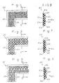
- Figure 4 is another embodiment of the seal means of the present invention showing a front view of a corner portion of the seal means.
- Figure 5 is a cross-sectional view taken along line 5-5 of Figure 4.
- Figure 6 is another embodiment of the seal means of the present invention showing a front view of a corner portion of the seal means.
- Figure 7 is a cross-sectional view taken along line 7 of Figure 6.
- Figure 8 is another embodiment of the seal means of the present invention showing a front view of a corner portion of the seal means.
- Figure 9 is a cross-sectional view taken along line 9-9 of Figure 8.
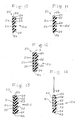
- Figure 10 is another embodiment of the seal means of the present invention showing a cross-sectional view of the seal means.
- Figure 11 is another embodiment of the seal means of the present invention showing a cross-sectional view of the seal means.
- Figure 12 is another embodiment of the seal means of the present invention showing a cross-sectional view of the seal means with rigidifying material embedded therein.
- Figure 13 is another embodiment of the seal means of the present invention showing a cross-sectional view of the seal means having a bi-layer construction.
- Figure 14 is another embodiment of the seal means of the present invention showing a cross-sectional and exploded view of the seal means with a spacer member.
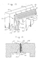
- Figure 15 is a perspective view of a corner portion of an electrolysis cell assembly showing adjacent filter press cell frames and an embodiment of the seal means of the present invention.
- Figure 16 is a cross-sectional view of a portion of an electrolysis cell assembly of Figure 15.
- Figure 17 is a perspective and partially cut-away view of a corner portion of an electrolysis cell assembly showing adjacent filter press cell frames, a membrane, and another embodiment of the seal means of the present invention.
- Figure 18 is a cross-sectional view of a portion of the electrolysis cell assembly of Figure 17.
- a frame-shaped seal means is shown in Figures 1 and 2. Additional embodiments of seal means 20 are shown in Figures 3-14.
- the seal means 20, in this instance, is in the shape of a picture frame and rectangular in shape, but is not to be limited thereto as other shapes such as square or circular shapes may be used.
- the seal means 20 includes a substantially solid body 21a having top and bottom walls 21b which are preferably parallel, a generally planar side wall 21c, and a side wall 21d defined by a nonplanar or an uneven surface.
- “Substantially solid body” means the body may be porous or contain other materials embedded therein.
- the uneven surface in this instance, may be in the form a series of ridges 22 and grooves 23 running parallel to each other.
- the ridges 22 and grooves 23 are rounded at the corners of the frame-shaped seal means 20, but this is not necessary for purposes of the invention.
- the ridges 22 and groves 23 are generally triangular in shape, although any crosssectional shape may be used.
- the ridges 22 and grooves 23 may be of generally rectangular cross-section or, as shown in Figure 11, the ridges 22 and grooves 23 may be of generally semicircular cross-section.
- the seal means 20 may contain flat side portions 24, as shown in Figure 2.
- Figure 3 shows a seal means 20 without such flat side portions.
- the uneven surface designated generally as the side wall 21d may be in the form of a plurality of concavities with ridge 25 as illustrated in Figures 4-9.
- the concavities may be pyramidal-shaped ( Figure 4), diamond-shaped ( Figure 6), or honeycomb-shaped ( Figure 8).
- the concavities provide ridges 25 adapted for contacting the gasket surface area of a cell frame member and providing an interface between the seal means and the gasket surface area of the cell frame member for sealing.
- the concavities advantageously provide non-interconnecting cup-like traps adapted for catching random gas or electrolyte leaks.
- the concavities provide a cup-like suction effect when compressed and are adapted for a gasket-to-frame attachment for vertically walled seal surfaces.
- Seal means 20 may be constructed of any suitable material.
- the gasket may be made of rubber or elastomer material.
- the gasket is made of a material which is physically and chemically stable, e.g., when contacted with an electrolyte and products of electrolysis present such as in a chlor-alkali cell.
- the gasket In the production of chlorine and caustic, for example, the gasket must, of course, be substantially inert to acid, brine, chlorine, hydrogen and caustic.
- the gasket is preferably electrically nonconductive.
- the gasket should be of a material having high volume resistivity and good sealability after it has been compressed.
- Suitable materials which can be employed in accordance with this invention include, but are not limited to, for example, neoprene, butyl rubber, ethylene-propylene diene monomer (EPDM), chlorinated polyethylene (CPE) and a polytetrafluoroethylene (PTFE) material such as GORE-TEX®, a Trademark of W. L. Gore & Associates, Inc., or Teflon®, a Trademark of E. I. duPont de Nemours & Company. The durameter of these materials may range from 50 to 80 Shore A.
- Figure 12 shows another and preferred embodiment of the present invention wherein seal means 20 includes a reinforcement or rigidifying material 26 embedded in the solid body 21a.
- a rigidifying material may be used with any of the seal means 20 of the Figures 1-18, inclusive, if desired.
- the purpose of the rigidifying material is to minimize local compression and stiffen quadralaterally the seal means against stretch.
- the rigidifying material 26 may be made of any material inert to the gasket materials above, for example, an aromatic polyamide fiber, such as Kevlar®, a Trademark of E. I. duPont de Nemours & Company, polyester, nylon or fabric.
- the rigidifying material 26 may also be a screen of metal such as, for example, titanium.
- the rigidifying material 26, viewed in cross-section may be any shape or form.
- a fabric material is embedded within the solid body 21a.
- the seal means 20 is of a bi-layered construction comprising a first layer 31 and a second layer 32 attached to each other at interface 33 by well known methods such as adhesives.
- the materials of the first and second layers may be selected from the materials described above for seal means 20.
- the first and second layers 31 and 32, respectively, may be made identical or different materials with identical or different hardness.
- the first layer 31 may be made of CPE with a hardness of 40 shore A and the second layer 32 may be made of EPDM with a hardness of 80 shore A.
- FIG 14 Yet another embodiment of the present invention is shown in Figure 14.
- a seal means 20 with a back portion 41 and a front portion 42 connected at a bottom portion 43 forming a slot 44 adapted to receive a spacer frame 45.
- the front portion 42 may contain ridges 22 and grooves 23 of any shape in cross-section as described above.
- the back portion 41 may be thinner than the front portion 42.
- the spacer frame 45 is positioned in slot 44. By shimming the spacer frame 45 into the slot 44, the seal means may be provided with further support to minimize excessive compression to the seal means due to nonparallelism or thickness variation of the frame assembly.
- the spacer frame 45 is preferably wedge-shaped but may be of any desired shaped.
- the slot 44 may also be any shape to accommodated the spacer frame 45 which may be made of a polyvinylchloride polymer, Kynar®, and other thermoplastic materials that can provide the rigidity necessary to obtain a seal.
- the seal means 20 may be used in electrolysis cells not employing a separator such as an electrolysis cell used for the production of a chlorate as illustrated in Figures 15 and 16, wherein the seal means 20 is interposed between two electrode frame members 51 and 52.
- the seal means 20 is interposed between a pair of adjacent filter press frames 51 and 52 without a separator.
- frame 51 will be referred hereto as the anode frame 51 and frame 52 will be referred hereto as the cathode frame 52.
- the anode and cathode frames are structured such that an anode and a cathode are attached on opposite faces or sides of the structure and electrically connected through the structure.
- the electrolysis cell assembly is typical of a filter presstype electrolytic cell unit which may be monopolar or bipolar.
- a filter presstype electrolytic cell unit which may be monopolar or bipolar.
- the invention will be described herein with reference to a bipolar, electrolytic filter press-type cell.
- the seal means of the present invention is useful in filter press-type cells, for example, as described in U. S. Patent Nos. 4,108,742 and 4,111,779.
- the seal means of the present invention may be used in an electrolysis cell with a separator, for example, chlor-alkali cells used for the production of chlorine and alkali metal hydroxide.
- a chlor-alkali cell assembly including a separator 60 and two seal means 20 positioned between frames 51 and 52.
- the separator 60 is interposed between the two seal means 20 while the two seal means 20 including the separator 60 are interposed between the lateral faces 53 and 54 of frames 51 and 52, respectively.
- the grooved side wall of each seal means is in contact with the lateral faces 53 and 54 of electrode frames 51 and 52, respectively, and the planar side wall 21c of the seal means is in contact with the separator 60.
- the top and bottom walls 21b of each of the pair of seal means 20 essentially face opposite each other with the separator 60 interposed between the planar side surfaces of the seal means.
- Separator 60 used in the present invention may be a diaphragm or a membrane. Particularly useful in the present invention are ion-exchange membrane separators used in filter press-type cells. Preferably, membranes having ion-exchange properties and which are substantially impervious to the hydrodynamic flow of the electrolyte and the passage of gas products produced during electrolysis, are used.
- the materials of construction for frames 51 and 52 may be any which are resistant to corrosion by the electrolytes and the products of electrolysis.
- the frames 51 and 52 may be any shape used in typical electrolysis cells, for example, in the shape of rectangular bars, C or U channels, cylindrical tubes, elliptical tubes as well as being I-shaped or H-shaped.
- the cross-section shape of the frame members are I-shaped.
- a pair of the seal means 20 are interposed between the cell frames 51 and 52 so that the ridges 22 bear against the lateral face 35 and 54 of frames 51 and 52, respectively, at the points of contact.
- the membrane 60 is interposed and in contact with the flat or planar surfaces 21c of the seal means 20
- a compressive force for example, using a hydraulic ram is applied to the cell frames to compress the seal means with the membrane together.
- the ridges 22 deform slightly which is not shown in Figure 18.
- the nominal compressive stress normally used may range from 345 to 13,800 kPa. Preferably, from 345 to 4100 kPa and more preferably from 345 to 1400 kPa. However, the lowest stress required for effectuating a desired joint tightness is desirable for material endurance.
- One advantage of the present seal means over conventional seal means is that an interfacial seal may be obtained at a lower nominal compressive stress with seal means having ridges and grooves than with seal means without ridges and grooves. Consequently, there is less compressive load on the membrane, and the intrinsic oozing of the gasketing material is significantly reduced. Since oozing is reduced, the tearing or breaking of a membrane is also reduced during compression of the seal means and membrane via the cell frame members which in turn enhances the expected service life of the membrane.
- a 60 cm by 60 cm test cell consisting of two cell frames provided with piping connections for air and hot water service is used to test the "sealability" of gaskets up to a cell pressure of 345 kPa.
- a gasket is cemented to the flange using a rubber cement.
- the membrane is then taped to one of the test cell frames. Care is taken to avoid wrinkles around the periphery of the membrane.
- the assembly is then placed in a hydraulic press testing machine and squeezed lightly to hold the assembly just enough to inspect for an even seating of the sealing surfaces.
- the assembly is then squeezed to a gasket loading of approximately 345 kPa and held for about 20 minutes.
- the loading is then relaxed to approximately 170 kPa and held for about 10 minutes.
- the loading is then increased to approximately 510 kPa.
- the cell is then filled with tap water and the water circulated therethrough. If wetting of the membrane or leakage of water is observed, the procedure is started over again.
- the gasket loading is increased to approximately 7600 kPa in increments of about 103 kPa. Each increment is held for 20 minutes before raising the loading to the next increment.
- the gasket loading is then decreased to half of its high value. This process is known as "preconditioning" the gasketed assembly.
- the temperature of the circulating water is incrementally raised to 93.3°C by increments of 11°C per 30 minutes and the internal cell pressure (air-padding) is raised incrementally to 170 kPa at 34 kPa increments per 25 minutes.
- Air leakage is calculated by measuring the drop in air pressure during several half-hour intervals; while the temperature remains substantially constant. Thus, a prorated air loss per day was calculated.
- the cell assembly Upon completion of the test, the cell assembly is disassembled. The gasket is examined for permanent deformation and the membrane is examined for thinning and/or tears.
- the general procedure above was followed to test a pair of gaskets having a plurality of ridges and grooves of triangular shape in cross-section, herein serrated gaskets, shown in Figures 11 and 12.
- the serrated gaskets were made of EDPM rubber obtained from Sealmaster Corporation, Kent, Ohio.
- the size of the serrated gaskets were 63 cm by 63 cm by 3.1 mm.
- the membrane tested was Nafion® 321.
- the cell frame was maintained at 207 kPa and the water circulated was maintained at 93°C for 140 hours.
- the gasket loading was about 480 kPa. Visual observation of the serrated gaskets and membrane after the testing period showed some pressure marks with an acceptable amount of stretching, but the membrane showed no sign of tearing or breaking.
Landscapes
- Engineering & Computer Science (AREA)
- Chemical & Material Sciences (AREA)
- General Engineering & Computer Science (AREA)
- Chemical Kinetics & Catalysis (AREA)
- Electrochemistry (AREA)
- Materials Engineering (AREA)
- Metallurgy (AREA)
- Organic Chemistry (AREA)
- Mechanical Engineering (AREA)
- Electrolytic Production Of Non-Metals, Compounds, Apparatuses Therefor (AREA)
Claims (12)
- Abdichtmittel für eine elektrolytische Zelle, umfassend ein im wesentlichen festes Teil und enthaltend obere und untere Wände, eine im allgemeinen ebene Seitenwand, die zum Kontakt mit einer im allgemeinen ebenen Oberfläche ausgebildet ist, und eine Seitenwand, die durch eine unebene Oberfläche definiert ist und zum Kontakt mit mindestens einem Elektrodenrahmen ausgebildet ist,
dadurch gekennzeichnet, daß die unebene Oberfläche eine Vielzahl von Wölbungen mit einer im allgemeinen pyramidalen, diamant- oder wabenartigen Form ist. - Abdichtmittel nach Anspruch l, worin das im wesentlichen feste Teil darin eingebettetes Verstärkungsmaterial enthält.
- Abdichtmittel nach Anspruch 2, worin das Verstärkungsmaterial ein Kunstharzmaterial, ein Metallblech oder Sieb oder ein Gewebematerial ist.
- Abdichtmittel nach Anspruch 3, worin das Kunstharzmaterial aus Ethylenpropylendien und chloriertem Polyethylen ausgewählt ist.
- Abdichtmittel nach Anspruch 1, worin das im wesentlichen feste Teil eine erste Schicht und eine zweite Schicht umfaßt, wobei die Schichten an einer Zwischenfläche miteinander befestigt sind, um eine doppelschichtige Abdichtung zu bilden.
- Abdichtmittel nach Anspruch 5, worin die erste Schicht aus einem Material hergestellt ist, das eine unterschiedliche Härte als das Material der zweiten Schicht aufweist.
- Elektrolysezellanordnung, enthaltend mindestens ein erstes Abdichtmittel nach den Ansprüchen 1 - 6, das zwischen mindestens zwei benachbarte Elektrodenrahmen eingefügt ist.
- Zellanordnung nach Anspruch 7, dadurch gekennzeichnet, daß sie eine Trennschicht umfaßt, die zwischen dem ersten Abdichtmittel und einem ersten Elektrodenrahmen eingefügt ist, worin die ebene Seitenwand des ersten Abdichtmittels in Kontakt mit einer ersten Seite des Trennmittels ist und die unebene Seitenwand des ersten Abdichtmittels in Kontakt mit einem zweiten Elektrodenrahmen ist.
- Zellanordnung nach Anspruch 8, dadurch gekennzeichnet, daß sie weiterhin ein zweites Abdichtmittel enthält, das zwischen dem Trennmittel und dem ersten Elektrodenrahmen eingefügt ist, wobei die ebene Seitenwand in Kontakt mit der zweiten Seite des Trennmittels steht, und die Seitenwand, die durch eine unebene Oberfläche definiert ist, in Kontakt mit dem ersten Elektrodenrahmen steht.
- Verfahren zum Abdichten einer Elektrolysezelle, umfassend das Einfügen von mindestens einem ersten Abdichtmittel nach einem der Ansprüche 1 - 6 zwischen mindestens zwei benachbarte Elektrodenrahmen der Zelle und Anwenden einer Kompressionskraft auf die Rahmen.
- Verfahren nach Anspruch 10, enthaltend den Schritt des Einfügens einer Trennschicht zwischen das erste Abdichtmittel und einen ersten Elektrodenrahmen, worin die Seitenwand des ersten Abdichtmittels in Kontakt mit einer Seite des Trennmittels steht und die Seitenwand des ersten Abdichtmittels in Kontakt mit einem zweiten Elektrodenrahmen steht.
- Verfahren nach Anspruch 11, enthaltend weiterhin ein zweites Abdichtmittel zwischen dem Trennmittel und dem ersten Elektrodenrahmen, wobei die im allgemeinen ebene Seitenwand des zweiten Abdichtmittels in Kontakt mit der anderen Seite des Trennmittels steht und eine Seitenwand, die durch eine unebene Oberfläche definiert ist, in Kontakt mit dem ersten Elektrodenrahmen steht.
Priority Applications (1)
| Application Number | Priority Date | Filing Date | Title |
|---|---|---|---|
| DE8787101207T DE3768934D1 (de) | 1987-01-29 | 1987-01-29 | Dichtungseinrichtung fuer elektrolysezelle. |
Applications Claiming Priority (1)
| Application Number | Priority Date | Filing Date | Title |
|---|---|---|---|
| US06/761,923 US4721555A (en) | 1985-08-02 | 1985-08-02 | Electrolysis cell seal means |
Publications (2)
| Publication Number | Publication Date |
|---|---|
| EP0276351A1 EP0276351A1 (de) | 1988-08-03 |
| EP0276351B1 true EP0276351B1 (de) | 1991-03-27 |
Family
ID=25063622
Family Applications (1)
| Application Number | Title | Priority Date | Filing Date |
|---|---|---|---|
| EP87101207A Expired EP0276351B1 (de) | 1985-08-02 | 1987-01-29 | Dichtungseinrichtung für Elektrolysezelle |
Country Status (2)
| Country | Link |
|---|---|
| US (1) | US4721555A (de) |
| EP (1) | EP0276351B1 (de) |
Cited By (2)
| Publication number | Priority date | Publication date | Assignee | Title |
|---|---|---|---|---|
| WO2025149211A1 (de) | 2024-01-12 | 2025-07-17 | Siemens Energy Global GmbH & Co. KG | Pfas-freies dichtkonzept für die alkalische wasserelektrolyse |
| WO2025180771A1 (de) | 2024-02-27 | 2025-09-04 | Siemens Energy Global GmbH & Co. KG | Zellkonzept mit einer neuartigen kathodenstruktur sowie eines entsprechenden zellrahmens für die alkalische wasserelektrolyse |
Families Citing this family (35)
| Publication number | Priority date | Publication date | Assignee | Title |
|---|---|---|---|---|
| US4877499A (en) * | 1984-11-05 | 1989-10-31 | The Dow Chemical Company | Membrane unit for electrolytic cell |
| DE3705926C1 (de) * | 1987-02-25 | 1988-08-18 | Metallgesellschaft Ag | Dichtung fuer die Elektrodenrahmen einer Membranelektrolyse |
| US4940518A (en) * | 1988-09-26 | 1990-07-10 | The Dow Chemical Company | Combination seal member and membrane holder for a filter press type electrolytic cell |
| US4898653A (en) * | 1988-09-26 | 1990-02-06 | The Dow Chemical Company | Combination electrolysis cell seal member and membrane tentering means |
| US4886586A (en) * | 1988-09-26 | 1989-12-12 | The Dow Chemical Company | Combination electrolysis cell seal member and membrane tentering means for a filter press type electrolytic cell |
| US4915803A (en) * | 1988-09-26 | 1990-04-10 | The Dow Chemical Company | Combination seal and frame cover member for a filter press type electrolytic cell |
| US4892632A (en) * | 1988-09-26 | 1990-01-09 | The Dow Chemical Company | Combination seal member and membrane holder for an electrolytic cell |
| US5441621A (en) * | 1993-12-22 | 1995-08-15 | United Technologies Corporation | Electrochemical cell having crossed-ridge sealing surface |
| US5942091A (en) * | 1997-11-07 | 1999-08-24 | Oxytech Systems, Inc. | Electrolytic cell sealing means |
| US7087339B2 (en) * | 2002-05-10 | 2006-08-08 | 3M Innovative Properties Company | Fuel cell membrane electrode assembly with sealing surfaces |
| US7217471B2 (en) * | 2002-05-17 | 2007-05-15 | 3M Innovative Properties Company | Membrane electrode assembly with compression control gasket |
| US20040096723A1 (en) * | 2002-11-14 | 2004-05-20 | 3M Innovative Properties Company | Fuel cell gasket |
| WO2005087353A1 (en) * | 2004-03-09 | 2005-09-22 | Pierce Biotechnology, Inc. | Dialysis device with air chamber |
| GB2434845B (en) * | 2006-02-01 | 2010-10-13 | Intelligent Energy Ltd | Variable compressibility gaskets |
| US7866670B2 (en) * | 2006-11-08 | 2011-01-11 | Federal-Mogul World Wide, Inc. | Static gasket |
| US20080170700A1 (en) * | 2007-01-17 | 2008-07-17 | Prashanth Darba | System for controlling access to digital information |
| US8316590B2 (en) * | 2009-03-20 | 2012-11-27 | Northern States Metals Company | Support system for solar panels |
| US20110220596A1 (en) * | 2009-03-20 | 2011-09-15 | Northern States Metals Company | Support system for solar panels |
| US8256169B2 (en) | 2009-03-20 | 2012-09-04 | Northern States Metals Company | Support system for solar panels |
| US8240109B2 (en) * | 2009-03-20 | 2012-08-14 | Northern States Metals Company | Support system for solar panels |
| CN102041522B (zh) * | 2009-10-19 | 2012-05-30 | 江阴市生一氯碱设备制造有限公司 | 电解槽密封垫片的制备方法 |
| DE102010018677A1 (de) * | 2010-04-28 | 2011-11-03 | Watermann Polyworks Gmbh | Dichtungsmanschette |
| US8839573B2 (en) | 2011-02-11 | 2014-09-23 | Northern States Metals Company | Spring clip |
| DE102011100768A1 (de) | 2011-05-06 | 2012-12-06 | Bayer Material Science Ag | Elektrochemische Zelle mit Rahmendichtung zur alternativen Abdichtung gegenRandläufigkeiten des Elektrolyten |
| US9248407B2 (en) | 2012-09-14 | 2016-02-02 | Pierce Biotechnology, Inc. | Dialysis device |
| US9303663B2 (en) | 2013-04-11 | 2016-04-05 | Northern States Metals Company | Locking rail alignment system |
| US9963795B2 (en) * | 2013-04-30 | 2018-05-08 | Asahi Kasei Kabushiki Kaisha | Gasket and electrolyser |
| FR3008428B1 (fr) * | 2013-07-11 | 2015-08-07 | Ceth² | Joint pour pile d'electrolyseur et pile d'electrolyseur equipee d'un tel joint |
| CA2994962A1 (en) | 2015-08-11 | 2017-02-16 | Nuvera Fuel Cells, LLC | Multi-component bipolar plate for an electrochemical cell |
| JP6773505B2 (ja) * | 2016-09-29 | 2020-10-21 | Nok株式会社 | ガスケット |
| JP6773504B2 (ja) * | 2016-09-29 | 2020-10-21 | Nok株式会社 | ガスケット |
| US11149853B2 (en) * | 2018-05-15 | 2021-10-19 | Dell Products L.P. | Airflow sealing by flexible rubber with I-beam and honeycomb structure |
| AU2020318538B2 (en) * | 2019-07-19 | 2022-04-07 | De Nora Permelec Ltd | Gasket for electrolysis vessels, and electrolysis vessel using same |
| CN120826497A (zh) * | 2022-12-29 | 2025-10-21 | 国际人造丝公司 | 用于电解器的热塑性硫化垫圈 |
| AT526232B1 (de) * | 2023-05-17 | 2024-01-15 | Andritz Ag Maschf | Elektrolysezelle und Elektrolysevorrichtung mit einer Elektrolysezelle |
Family Cites Families (17)
| Publication number | Priority date | Publication date | Assignee | Title |
|---|---|---|---|---|
| FR849454A (fr) * | 1938-07-29 | 1939-11-24 | Joint étanche et son mode d'application | |
| FR1585692A (de) * | 1968-09-20 | 1970-01-30 | ||
| US3964932A (en) * | 1973-01-26 | 1976-06-22 | Esb Incorporated | Battery having deformations in a metal layer |
| FR2280432A1 (fr) * | 1974-07-29 | 1976-02-27 | Rhone Poulenc Ind | Cellule d'electrolyse a elements bipolaires pour l'electrolyse notamment de solutions de sels alcalins |
| FR2297672A1 (fr) * | 1975-01-14 | 1976-08-13 | Rech Tech Et Indles | Electrolyseur |
| US4130468A (en) * | 1975-11-28 | 1978-12-19 | Oronzio De Nora Impianti Elettrochimici S.P.A. | Method of operation of an electrolysis cell with vertical anodes and cathodes |
| US4139448A (en) * | 1978-01-03 | 1979-02-13 | Hooker Chemicals & Plastics Corp. | Separating web - electrolytic compartment frames assembly for electrolytic apparatuses |
| US4342460A (en) * | 1978-03-30 | 1982-08-03 | Hooker Chemicals & Plastics Corp. | Gasket means for electrolytic cell assembly |
| DE2821981A1 (de) * | 1978-05-19 | 1979-11-22 | Hooker Chemicals Plastics Corp | Elektrolysezelle mit mehreren aneinandergereihten elektrodenrahmen |
| US4175025A (en) * | 1978-07-07 | 1979-11-20 | Basf Wyandotte Corporation | Sealed membrane filter press electrolytic cells |
| US4313812A (en) * | 1980-03-10 | 1982-02-02 | Olin Corporation | Membrane electrode pack cells designed for medium pressure operation |
| US4431502A (en) * | 1980-11-05 | 1984-02-14 | Olin Corporation | Sealing means for filter press cells |
| US4441977A (en) * | 1980-11-05 | 1984-04-10 | Olin Corporation | Electrolytic cell with sealing means |
| US4344633A (en) * | 1981-05-22 | 1982-08-17 | Diamond Shamrock Corporation | Gasket for electrolytic cell |
| JPS5835272A (ja) * | 1981-08-28 | 1983-03-01 | Nippon Denso Co Ltd | 内燃機関 |
| GB8312043D0 (en) * | 1982-05-19 | 1983-06-08 | Ici Plc | Electrolytic cell and gasket |
| US4470608A (en) * | 1982-06-14 | 1984-09-11 | The Dow Chemical Company | Resilient gasket having auxiliary resiliency means |
-
1985
- 1985-08-02 US US06/761,923 patent/US4721555A/en not_active Expired - Fee Related
-
1987
- 1987-01-29 EP EP87101207A patent/EP0276351B1/de not_active Expired
Cited By (2)
| Publication number | Priority date | Publication date | Assignee | Title |
|---|---|---|---|---|
| WO2025149211A1 (de) | 2024-01-12 | 2025-07-17 | Siemens Energy Global GmbH & Co. KG | Pfas-freies dichtkonzept für die alkalische wasserelektrolyse |
| WO2025180771A1 (de) | 2024-02-27 | 2025-09-04 | Siemens Energy Global GmbH & Co. KG | Zellkonzept mit einer neuartigen kathodenstruktur sowie eines entsprechenden zellrahmens für die alkalische wasserelektrolyse |
Also Published As
| Publication number | Publication date |
|---|---|
| EP0276351A1 (de) | 1988-08-03 |
| US4721555A (en) | 1988-01-26 |
Similar Documents
| Publication | Publication Date | Title |
|---|---|---|
| US4721555A (en) | Electrolysis cell seal means | |
| US4915803A (en) | Combination seal and frame cover member for a filter press type electrolytic cell | |
| US4892632A (en) | Combination seal member and membrane holder for an electrolytic cell | |
| CA1115660A (en) | Sealed membrane filter press electrolytic cells | |
| US4898653A (en) | Combination electrolysis cell seal member and membrane tentering means | |
| EP0195072B1 (de) | Dichtungsband für elektrolytische zellen | |
| US4654134A (en) | Combination seal and tentering means for electrolysis cells | |
| US4894128A (en) | Membrane unit for electrolytic cell | |
| EP0094772B1 (de) | Elektrolysezelle und hierfür geeignete Dichtung | |
| EP2734658A2 (de) | Rahmenkonzept für einen elektrolyseur, verfahren dafür und verwendung davon | |
| US4389289A (en) | Bipolar electrolyzer | |
| US4431502A (en) | Sealing means for filter press cells | |
| US4219394A (en) | Membrane assembly for electrolytic cells | |
| EP0051380B1 (de) | Dichtungseinrichtung für Filterpressenzellen | |
| EP0055931B1 (de) | Dichtungsschmiermittel | |
| EP0402909B1 (de) | Dichtungen für Filterpress-Typ-Zellen | |
| EP0055930A1 (de) | Elektrodenabstandssteuerung für eine elektrolytische Zelle | |
| EP0183096B1 (de) | Membranelement für elektrolytische Zelle | |
| US4940518A (en) | Combination seal member and membrane holder for a filter press type electrolytic cell | |
| US4886586A (en) | Combination electrolysis cell seal member and membrane tentering means for a filter press type electrolytic cell | |
| JPS63216990A (ja) | 電解槽の密封手段、電解槽アセンブリ、および電解槽密封方法 | |
| US4877499A (en) | Membrane unit for electrolytic cell | |
| EP0276350A1 (de) | Kombinierte Dichtungs- und Spannvorrichtung für Elektrolysezellen | |
| CN85108000A (zh) | 电解槽的密封 | |
| KR890002055B1 (ko) | 전해조 조립체 및 그 밀봉 방법 |
Legal Events
| Date | Code | Title | Description |
|---|---|---|---|
| PUAI | Public reference made under article 153(3) epc to a published international application that has entered the european phase |
Free format text: ORIGINAL CODE: 0009012 |
|
| 17P | Request for examination filed |
Effective date: 19870129 |
|
| AK | Designated contracting states |
Kind code of ref document: A1 Designated state(s): BE DE FR GB IT NL |
|
| 17Q | First examination report despatched |
Effective date: 19890508 |
|
| GRAA | (expected) grant |
Free format text: ORIGINAL CODE: 0009210 |
|
| AK | Designated contracting states |
Kind code of ref document: B1 Designated state(s): BE DE FR GB IT NL |
|
| REF | Corresponds to: |
Ref document number: 3768934 Country of ref document: DE Date of ref document: 19910502 |
|
| ET | Fr: translation filed | ||
| ITF | It: translation for a ep patent filed | ||
| PGFP | Annual fee paid to national office [announced via postgrant information from national office to epo] |
Ref country code: FR Payment date: 19911206 Year of fee payment: 6 |
|
| PGFP | Annual fee paid to national office [announced via postgrant information from national office to epo] |
Ref country code: DE Payment date: 19911219 Year of fee payment: 6 |
|
| PGFP | Annual fee paid to national office [announced via postgrant information from national office to epo] |
Ref country code: GB Payment date: 19920102 Year of fee payment: 6 |
|
| PGFP | Annual fee paid to national office [announced via postgrant information from national office to epo] |
Ref country code: BE Payment date: 19920107 Year of fee payment: 6 |
|
| PLBE | No opposition filed within time limit |
Free format text: ORIGINAL CODE: 0009261 |
|
| STAA | Information on the status of an ep patent application or granted ep patent |
Free format text: STATUS: NO OPPOSITION FILED WITHIN TIME LIMIT |
|
| PGFP | Annual fee paid to national office [announced via postgrant information from national office to epo] |
Ref country code: NL Payment date: 19920131 Year of fee payment: 6 |
|
| 26N | No opposition filed | ||
| PG25 | Lapsed in a contracting state [announced via postgrant information from national office to epo] |
Ref country code: GB Effective date: 19930129 |
|
| PG25 | Lapsed in a contracting state [announced via postgrant information from national office to epo] |
Ref country code: BE Effective date: 19930131 |
|
| BERE | Be: lapsed |
Owner name: THE DOW CHEMICAL CY Effective date: 19930131 |
|
| PG25 | Lapsed in a contracting state [announced via postgrant information from national office to epo] |
Ref country code: NL Effective date: 19930801 |
|
| NLV4 | Nl: lapsed or anulled due to non-payment of the annual fee | ||
| GBPC | Gb: european patent ceased through non-payment of renewal fee |
Effective date: 19930129 |
|
| PG25 | Lapsed in a contracting state [announced via postgrant information from national office to epo] |
Ref country code: FR Effective date: 19930930 |
|
| PG25 | Lapsed in a contracting state [announced via postgrant information from national office to epo] |
Ref country code: DE Effective date: 19931001 |
|
| REG | Reference to a national code |
Ref country code: FR Ref legal event code: ST |
|
| PG25 | Lapsed in a contracting state [announced via postgrant information from national office to epo] |
Ref country code: IT Free format text: LAPSE BECAUSE OF NON-PAYMENT OF DUE FEES Effective date: 20050129 |