EP0276458B1 - Dispositif pour ajouter l'eau pour la production de vapeur dans un appareil à cuire - Google Patents
Dispositif pour ajouter l'eau pour la production de vapeur dans un appareil à cuire Download PDFInfo
- Publication number
- EP0276458B1 EP0276458B1 EP87118906A EP87118906A EP0276458B1 EP 0276458 B1 EP0276458 B1 EP 0276458B1 EP 87118906 A EP87118906 A EP 87118906A EP 87118906 A EP87118906 A EP 87118906A EP 0276458 B1 EP0276458 B1 EP 0276458B1
- Authority
- EP
- European Patent Office
- Prior art keywords
- container
- water
- drawer
- control disc
- follower pin
- Prior art date
- Legal status (The legal status is an assumption and is not a legal conclusion. Google has not performed a legal analysis and makes no representation as to the accuracy of the status listed.)
- Expired - Lifetime
Links
Images


Classifications
-
- F—MECHANICAL ENGINEERING; LIGHTING; HEATING; WEAPONS; BLASTING
- F24—HEATING; RANGES; VENTILATING
- F24C—DOMESTIC STOVES OR RANGES ; DETAILS OF DOMESTIC STOVES OR RANGES, OF GENERAL APPLICATION
- F24C15/00—Details
- F24C15/32—Arrangements of ducts for hot gases, e.g. in or around baking ovens
- F24C15/322—Arrangements of ducts for hot gases, e.g. in or around baking ovens with forced circulation
- F24C15/327—Arrangements of ducts for hot gases, e.g. in or around baking ovens with forced circulation with air moisturising
Definitions
- the invention relates to a device for adding water to generate steam in a cooking device.
- DE-A-16 79 196 describes a kitchen stove which is suitable for cooking with steam in the oven and the muffle bottom of which has a trough-like depression for receiving the water to be evaporated.
- the water can obviously only be added by opening the loading door and pouring from a vessel into the trough-like depression.
- this is an unsatisfactory option for operating the cooker.
- some cooking and baked goods are treated much better by steam, today even in fitted kitchens with built-in ovens in the surrounding cupboards and optionally with a built-in hob, in addition to the optional switching on of the radiators for top and / or bottom heat and possibly one Hot air circulation fan, a possibility of steam generation is provided.
- the object of the invention is to simplify the addition of water to such cooking devices.
- Water can be conveniently added to the cooking space or an evaporation vessel via the vessel designed as a drawer in the area of the control panel. This process can also be triggered automatically by a timer at a specified time.
- the housing 2 surrounding the oven muffle 1 of a built-in oven according to FIG. 1 is only indicated schematically.
- a pot-like evaporation vessel 4 is inserted, which is connected to a water supply line 5.
- the water supply line 5 starts from a water filling container designed as a drawer 6, which is arranged in the area of the control panel 7 above the loading door 8. It is no problem for the housewife to pull the drawer 6 outwards and fill in the required amount of water.
- the filled water flows into the evaporation tank 4 via the elastic water supply line 5 and is evaporated there by an electric heater.
- the usual vapor outlet opening 9 should e.g. be closed by a slide.
- the water filling container which is designed as a drawer, with a quick coupling at the connection point to the water supply line 5, which in the uncoupled state prevents the water spout but releases it in the coupled state.
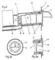
- FIG. 2 An embodiment for automatically emptying the drawer at a predetermined point in time is shown in FIG. 2.
- the container 10 is provided as a drawer, which can be inserted into the guide part 12 of the device housing provided for this purpose by means of the front handle 11.
- the container 10 can be rotated about its longitudinal axis within the guide part 12 and is therefore cylindrical and guided by spacing cams 13.
- An upper emptying or emptying cutout 14 in the container housing enables water to be poured into the container 10 pulled out of the device. Through the same cutout, when the container 10 rotates when the device is operating, the water escapes into the cooking space via a drain line 15.
- the rotation of the container at the desired time is effected by a control disk 17 driven by a clockwork 16, with which the container 10 can be coupled via a driving pin 18.
- the mode of operation is shown in FIG. 3.
- the arrow A is the zero mark on the control panel 7.
- the schematically indicated control disk 17 has a pair of adjusting cams 19 and a driving cam 20 in the effective range of which the driving pin 18 of the container 2 is located when it is pushed into the device.
- 3e and 3f show the movements of the parts belonging to one another at a setting of 20 minutes.
- FIGS. 2a + 2b a special handle design is shown in FIGS. 2a + 2b.
- the cylindrical, water-absorbing middle part 21 of the container 10 is preceded by a chamber 22, which is covered by the front half wall part 23.
- a handle web 24 crossing the chamber, which extends from the front wall part 23 to the central part 21, facilitates the rotation of the container for winding up the clockwork.
Landscapes
- Engineering & Computer Science (AREA)
- Chemical & Material Sciences (AREA)
- Combustion & Propulsion (AREA)
- Mechanical Engineering (AREA)
- General Engineering & Computer Science (AREA)
- Cookers (AREA)
- General Preparation And Processing Of Foods (AREA)
Claims (12)
- Dispositif pour amener de l'eau en vue de produire de la vapeur dans un appareil de cuisson, en particulier pour une cuisinière à chauffage électrique du four de cuisson et à soufflante de circulation de l'air chaud, caractérisé en ce que l'amenée d'eau part d'un réservoir de remplissage réalisé sous forme de tiroir (6) et disposé dans la zone du panneau de manoeuvre (7).
- Dispositif selon la revendication 1, caractérisé en ce que le tiroir (6) est réalisé sous forme d'un réservoir susceptible d'être extrait de l'appareil, pouvant être relié à la conduite d'amenée d'eau (5) au moyen d'un accouplement rapide.
- Dispositif selon la revendication 1 ou 2, caractérisé en ce que le tiroir est réalisé sous forme d'un réservoir (10), susceptible de tourner autour de son axe longitudinal, susceptible d'être accouplé à un disque de commande rotatif (17) d'une minuterie.
- Dispositif selon la revendication 3, caractérisé en ce que le tiroir présente une partie centrale cylindrique (21), recevant l'eau, qui est pourvue dans sa zone arrière supérieure d'une section de remplissage et/ou de purge (12).
- Dispositif selon l'une des revendications 1 à 4, caractérisé en ce que le réservoir (10) présente en face avant une prise (11) et un marquage de position initiale (B).
- Dispositif selon la revendication 5, caractérisé en ce que la prise se compose d'une partie de paroi (23), recouvrant, à peu près jusqu'à moitié de la face avant, une chambre (22) située devant la partie centrale cylindrique (21), et que, derrière cette partie de paroi, est prévue une nervure de prise (24), traversant la chambre (22) en direction longitudinale.
- Dispositif selon la revendication 6, caractérisé en ce que la nervure de prise (24) est réalisée sous forme d'une paroi intermédiaire, parcourant la chambre (22) au centre en direction radiale, depuis la partie de paroi avant jusqu'à la partie centrale (21).
- Dispositif selon l'une des revendications 1 à 7, caractérisé en ce que le réservoir (10) est pourvu à son extrémité arrière d'une tige d'entraînement (18), qui s'engage dans la zone des éléments d'entraînement du disque de commande (17) entraîné par une minuterie, lorsque le réservoir (10) est inséré.
- Dispositif selon la revendication 8, caractérisé en ce que la tige d'entraînement (18) sert à remonter le mécanisme de minuterie (16) du disque de commande (17), lorsque le récipient (10) est vide.
- Dispositif selon l'une des revendications 3 à 9, caractérisé en ce que le disque de commande (17) présente un couple de cames de réglage (19), entourant des deux côtés la tige d'entraînement (18), ainsi qu'une came d'entraînement (20).
- Dispositif selon la revendication 10, caractérisé en ce que les positions de la tige d'entraînement (18) et du couple de cames de réglage (19) coïncident lorsque le disque de commande (17) est en position zéro et que le réservoir (10) est en position initiale.
- Dispositif selon la revendication 11, caractérisé en ce qu'en position de zéro, le couple de cames de réglage (19) est décalé de 180° par rapport au marquage de position initiale (B) du réservoir (10).
Priority Applications (1)
| Application Number | Priority Date | Filing Date | Title |
|---|---|---|---|
| AT87118906T ATE67579T1 (de) | 1987-01-28 | 1987-12-19 | Vorrichtung zum zugeben von wasser zur dampferzeugung in ein gargeraet. |
Applications Claiming Priority (4)
| Application Number | Priority Date | Filing Date | Title |
|---|---|---|---|
| DE19873702455 DE3702455A1 (de) | 1987-01-28 | 1987-01-28 | Vorrichtung zum automatischen zugeben von wasser zur dampferzeugung in ein gargeraet |
| DE3702455 | 1987-01-28 | ||
| DE3703857 | 1987-02-07 | ||
| DE19873703857 DE3703857A1 (de) | 1987-02-07 | 1987-02-07 | Herd mit elektrischer beheizung des backofens |
Publications (3)
| Publication Number | Publication Date |
|---|---|
| EP0276458A2 EP0276458A2 (fr) | 1988-08-03 |
| EP0276458A3 EP0276458A3 (en) | 1989-11-02 |
| EP0276458B1 true EP0276458B1 (fr) | 1991-09-18 |
Family
ID=25851943
Family Applications (1)
| Application Number | Title | Priority Date | Filing Date |
|---|---|---|---|
| EP87118906A Expired - Lifetime EP0276458B1 (fr) | 1987-01-28 | 1987-12-19 | Dispositif pour ajouter l'eau pour la production de vapeur dans un appareil à cuire |
Country Status (3)
| Country | Link |
|---|---|
| EP (1) | EP0276458B1 (fr) |
| AT (1) | ATE67579T1 (fr) |
| DE (1) | DE3773172D1 (fr) |
Cited By (2)
| Publication number | Priority date | Publication date | Assignee | Title |
|---|---|---|---|---|
| US8196439B2 (en) * | 2007-05-02 | 2012-06-12 | Lg Electronics Inc. | Laundry machine including a support module with a drawer based detachable water supply |
| KR20200012310A (ko) * | 2018-07-26 | 2020-02-05 | 엘지전자 주식회사 | 조리기기 |
Families Citing this family (14)
| Publication number | Priority date | Publication date | Assignee | Title |
|---|---|---|---|---|
| DE4427460C2 (de) * | 1994-08-03 | 1997-07-10 | Bosch Siemens Hausgeraete | Backofen zum Dampfgaren |
| FR2814734B1 (fr) * | 2000-10-02 | 2003-01-17 | Brandt Cooking | Reservoir d'eau amovible, notamment pour un four de cuisson a la vapeur |
| KR101041071B1 (ko) * | 2003-12-30 | 2011-06-13 | 삼성전자주식회사 | 가열조리장치 |
| JP2006038316A (ja) | 2004-07-26 | 2006-02-09 | Toshiba Corp | 加熱調理器 |
| FR2887966B1 (fr) * | 2005-07-01 | 2007-08-17 | Seb Sa | Four comportant un dispositif d'evaporation d'eau |
| FR2887967B1 (fr) * | 2005-07-01 | 2007-08-17 | Seb Sa | Dispositif d'evaporation d'eau |
| KR101203840B1 (ko) * | 2006-12-14 | 2012-11-21 | 엘지전자 주식회사 | 세탁장치 및 그 제어방법 |
| DE102010063203A1 (de) * | 2010-12-16 | 2012-06-21 | BSH Bosch und Siemens Hausgeräte GmbH | Vorrichtung für ein Haushaltsgerät, mit einem Behälter für ein flüssiges oder pulverförmiges Medium |
| ES2536242T3 (es) * | 2011-05-13 | 2015-05-21 | Electrolux Home Products Corporation N.V. | Aparato, especialmente aparato doméstico |
| CN105455660B (zh) * | 2016-01-25 | 2017-10-03 | 宁波方太厨具有限公司 | 一种控制面板的上翻机构及应用有该上翻机构的蒸箱 |
| SI25270A (sl) * | 2016-09-16 | 2018-03-30 | Gorenje Gospodinjski Aparati, D.D. | Sestav gumba |
| IT202200003089A1 (it) * | 2022-02-18 | 2023-08-18 | Smeg Spa | Forno per la cottura di cibi |
| KR20240018307A (ko) * | 2022-08-02 | 2024-02-13 | 엘지전자 주식회사 | 조리기기 |
| EP4616121A1 (fr) * | 2022-11-09 | 2025-09-17 | Femas Metal San. Ve Tic. A.S. | Ensemble tiroir avec réservoir d'eau amovible pour four à vapeur |
Family Cites Families (1)
| Publication number | Priority date | Publication date | Assignee | Title |
|---|---|---|---|---|
| DE1679196A1 (de) * | 1967-04-27 | 1971-04-08 | Frank Sche Eisenwerke Ag | Kuechenherd |
-
1987
- 1987-12-19 DE DE8787118906T patent/DE3773172D1/de not_active Expired - Lifetime
- 1987-12-19 EP EP87118906A patent/EP0276458B1/fr not_active Expired - Lifetime
- 1987-12-19 AT AT87118906T patent/ATE67579T1/de not_active IP Right Cessation
Cited By (7)
| Publication number | Priority date | Publication date | Assignee | Title |
|---|---|---|---|---|
| US8196439B2 (en) * | 2007-05-02 | 2012-06-12 | Lg Electronics Inc. | Laundry machine including a support module with a drawer based detachable water supply |
| KR20200012310A (ko) * | 2018-07-26 | 2020-02-05 | 엘지전자 주식회사 | 조리기기 |
| KR20230048483A (ko) * | 2018-07-26 | 2023-04-11 | 엘지전자 주식회사 | 조리기기 |
| KR102564246B1 (ko) | 2018-07-26 | 2023-08-07 | 엘지전자 주식회사 | 조리기기 |
| KR102642751B1 (ko) | 2018-07-26 | 2024-02-29 | 엘지전자 주식회사 | 조리기기 |
| KR20240032775A (ko) * | 2018-07-26 | 2024-03-12 | 엘지전자 주식회사 | 조리기기 |
| KR102813797B1 (ko) | 2018-07-26 | 2025-05-27 | 엘지전자 주식회사 | 조리기기 |
Also Published As
| Publication number | Publication date |
|---|---|
| EP0276458A3 (en) | 1989-11-02 |
| DE3773172D1 (de) | 1991-10-24 |
| ATE67579T1 (de) | 1991-10-15 |
| EP0276458A2 (fr) | 1988-08-03 |
Similar Documents
| Publication | Publication Date | Title |
|---|---|---|
| EP0276458B1 (fr) | Dispositif pour ajouter l'eau pour la production de vapeur dans un appareil à cuire | |
| EP0277337B1 (fr) | Appareil à cuire ayant un espace à cuire chauffé par électricité et procédé pour opérer cet appareil à cuire | |
| DE69916175T2 (de) | Kochgerät | |
| DE3228220C2 (de) | Mikrowellen-Kombinationsherd mit einem Gassensor | |
| DE10154046A1 (de) | Haushaltsgerät | |
| DE3443477A1 (de) | Verfahren und vorrichtung zum wahlweisen betreiben eines gargeraetes mit umgewaelzter heissluft oder wasserdampf | |
| DE859597C (de) | Waschmaschine, insbesondere fuer den Haushalt | |
| DE3931217A1 (de) | Elektrische vorrichtung mit einem drehteller | |
| WO2005016096A1 (fr) | Appareil de cuisson servant a regenerer un article a cuire | |
| DE3314055A1 (de) | Mikrowellenherd | |
| EP0695503B1 (fr) | Four pour cuire à la vapeur | |
| DE19537751A1 (de) | Backofen zum Dampfgaren | |
| EP1862099A2 (fr) | Appareil de cuisine doté d'un générateur de vapeur et dispositif de chauffage abaissable | |
| DE2657929B2 (de) | Backofen, insbesondere mit Mitteln zur pyrolytischen Selbstreinigung | |
| DE3206606A1 (de) | Verriegelungsvorrichtung fuer die tuer eines backofens | |
| DE69300880T2 (de) | Dampfofen und Behälter zur Verwendung darin. | |
| DE102013106848A1 (de) | Gargerät mit einer Dampferzeugungseinrichtung | |
| DE3702455A1 (de) | Vorrichtung zum automatischen zugeben von wasser zur dampferzeugung in ein gargeraet | |
| DE3843039A1 (de) | Haushaltgeraet | |
| DE3703857A1 (de) | Herd mit elektrischer beheizung des backofens | |
| CH654193A5 (en) | Table-top oven device | |
| DE2502955C3 (de) | Vorrichtung zur Wärmebehandlung von Speisen | |
| DE3717224C2 (fr) | ||
| DE3630313C2 (fr) | ||
| DE1679045B1 (de) | Elektrischer Eierkochautomat |
Legal Events
| Date | Code | Title | Description |
|---|---|---|---|
| PUAI | Public reference made under article 153(3) epc to a published international application that has entered the european phase |
Free format text: ORIGINAL CODE: 0009012 |
|
| AK | Designated contracting states |
Kind code of ref document: A2 Designated state(s): AT BE CH DE FR GB IT LI NL |
|
| PUAL | Search report despatched |
Free format text: ORIGINAL CODE: 0009013 |
|
| AK | Designated contracting states |
Kind code of ref document: A3 Designated state(s): AT BE CH DE FR GB IT LI NL |
|
| 17P | Request for examination filed |
Effective date: 19891201 |
|
| 17Q | First examination report despatched |
Effective date: 19900913 |
|
| GRAA | (expected) grant |
Free format text: ORIGINAL CODE: 0009210 |
|
| RAP1 | Party data changed (applicant data changed or rights of an application transferred) |
Owner name: ELECTROLUX-JUNO KUECHENTECHNIK GMBH |
|
| AK | Designated contracting states |
Kind code of ref document: B1 Designated state(s): AT BE CH DE FR GB IT LI NL |
|
| REF | Corresponds to: |
Ref document number: 67579 Country of ref document: AT Date of ref document: 19911015 Kind code of ref document: T |
|
| REF | Corresponds to: |
Ref document number: 3773172 Country of ref document: DE Date of ref document: 19911024 |
|
| ITF | It: translation for a ep patent filed | ||
| GBT | Gb: translation of ep patent filed (gb section 77(6)(a)/1977) | ||
| PGFP | Annual fee paid to national office [announced via postgrant information from national office to epo] |
Ref country code: NL Payment date: 19911231 Year of fee payment: 5 |
|
| ET | Fr: translation filed | ||
| PGFP | Annual fee paid to national office [announced via postgrant information from national office to epo] |
Ref country code: BE Payment date: 19920107 Year of fee payment: 5 |
|
| PLBE | No opposition filed within time limit |
Free format text: ORIGINAL CODE: 0009261 |
|
| 26N | No opposition filed | ||
| PGFP | Annual fee paid to national office [announced via postgrant information from national office to epo] |
Ref country code: GB Payment date: 19921202 Year of fee payment: 6 |
|
| PGFP | Annual fee paid to national office [announced via postgrant information from national office to epo] |
Ref country code: AT Payment date: 19921229 Year of fee payment: 6 |
|
| PG25 | Lapsed in a contracting state [announced via postgrant information from national office to epo] |
Ref country code: BE Effective date: 19921231 |
|
| BERE | Be: lapsed |
Owner name: ELECTROLUX-JUNO KUCHENTECHNIK G.M.B.H. Effective date: 19921231 |
|
| PG25 | Lapsed in a contracting state [announced via postgrant information from national office to epo] |
Ref country code: NL Effective date: 19930701 |
|
| NLV4 | Nl: lapsed or anulled due to non-payment of the annual fee | ||
| PG25 | Lapsed in a contracting state [announced via postgrant information from national office to epo] |
Ref country code: GB Effective date: 19931219 Ref country code: AT Effective date: 19931219 |
|
| GBPC | Gb: european patent ceased through non-payment of renewal fee |
Effective date: 19931219 |
|
| PGFP | Annual fee paid to national office [announced via postgrant information from national office to epo] |
Ref country code: FR Payment date: 19941216 Year of fee payment: 8 |
|
| PG25 | Lapsed in a contracting state [announced via postgrant information from national office to epo] |
Ref country code: FR Effective date: 19960830 |
|
| REG | Reference to a national code |
Ref country code: FR Ref legal event code: ST |
|
| PGFP | Annual fee paid to national office [announced via postgrant information from national office to epo] |
Ref country code: CH Payment date: 19961220 Year of fee payment: 10 |
|
| PG25 | Lapsed in a contracting state [announced via postgrant information from national office to epo] |
Ref country code: LI Free format text: LAPSE BECAUSE OF NON-PAYMENT OF DUE FEES Effective date: 19971231 Ref country code: CH Free format text: LAPSE BECAUSE OF NON-PAYMENT OF DUE FEES Effective date: 19971231 |
|
| REG | Reference to a national code |
Ref country code: CH Ref legal event code: PL |
|
| PGFP | Annual fee paid to national office [announced via postgrant information from national office to epo] |
Ref country code: DE Payment date: 20010112 Year of fee payment: 14 |
|
| PG25 | Lapsed in a contracting state [announced via postgrant information from national office to epo] |
Ref country code: DE Free format text: LAPSE BECAUSE OF NON-PAYMENT OF DUE FEES Effective date: 20020702 |
|
| PG25 | Lapsed in a contracting state [announced via postgrant information from national office to epo] |
Ref country code: IT Free format text: LAPSE BECAUSE OF NON-PAYMENT OF DUE FEES Effective date: 20051219 |