EP0276467A2 - Druckwandler und dazugehöriger Schalter - Google Patents
Druckwandler und dazugehöriger Schalter Download PDFInfo
- Publication number
- EP0276467A2 EP0276467A2 EP87119042A EP87119042A EP0276467A2 EP 0276467 A2 EP0276467 A2 EP 0276467A2 EP 87119042 A EP87119042 A EP 87119042A EP 87119042 A EP87119042 A EP 87119042A EP 0276467 A2 EP0276467 A2 EP 0276467A2
- Authority
- EP
- European Patent Office
- Prior art keywords
- pressure receiving
- pressure
- switch
- pressure sensor
- receiving element
- Prior art date
- Legal status (The legal status is an assumption and is not a legal conclusion. Google has not performed a legal analysis and makes no representation as to the accuracy of the status listed.)
- Withdrawn
Links
Images






Classifications
-
- H—ELECTRICITY
- H01—ELECTRIC ELEMENTS
- H01H—ELECTRIC SWITCHES; RELAYS; SELECTORS; EMERGENCY PROTECTIVE DEVICES
- H01H35/00—Switches operated by change of a physical condition
- H01H35/24—Switches operated by change of fluid pressure, by fluid pressure waves, or by change of fluid flow
- H01H35/34—Switches operated by change of fluid pressure, by fluid pressure waves, or by change of fluid flow actuated by diaphragm
-
- H—ELECTRICITY
- H01—ELECTRIC ELEMENTS
- H01H—ELECTRIC SWITCHES; RELAYS; SELECTORS; EMERGENCY PROTECTIVE DEVICES
- H01H11/00—Apparatus or processes specially adapted for the manufacture of electric switches
-
- H—ELECTRICITY
- H01—ELECTRIC ELEMENTS
- H01H—ELECTRIC SWITCHES; RELAYS; SELECTORS; EMERGENCY PROTECTIVE DEVICES
- H01H11/00—Apparatus or processes specially adapted for the manufacture of electric switches
- H01H2011/0087—Welding switch parts by use of a laser beam
-
- Y—GENERAL TAGGING OF NEW TECHNOLOGICAL DEVELOPMENTS; GENERAL TAGGING OF CROSS-SECTIONAL TECHNOLOGIES SPANNING OVER SEVERAL SECTIONS OF THE IPC; TECHNICAL SUBJECTS COVERED BY FORMER USPC CROSS-REFERENCE ART COLLECTIONS [XRACs] AND DIGESTS
- Y10—TECHNICAL SUBJECTS COVERED BY FORMER USPC
- Y10T—TECHNICAL SUBJECTS COVERED BY FORMER US CLASSIFICATION
- Y10T29/00—Metal working
- Y10T29/49—Method of mechanical manufacture
- Y10T29/49002—Electrical device making
- Y10T29/49004—Electrical device making including measuring or testing of device or component part
-
- Y—GENERAL TAGGING OF NEW TECHNOLOGICAL DEVELOPMENTS; GENERAL TAGGING OF CROSS-SECTIONAL TECHNOLOGIES SPANNING OVER SEVERAL SECTIONS OF THE IPC; TECHNICAL SUBJECTS COVERED BY FORMER USPC CROSS-REFERENCE ART COLLECTIONS [XRACs] AND DIGESTS
- Y10—TECHNICAL SUBJECTS COVERED BY FORMER USPC
- Y10T—TECHNICAL SUBJECTS COVERED BY FORMER US CLASSIFICATION
- Y10T29/00—Metal working
- Y10T29/49—Method of mechanical manufacture
- Y10T29/49002—Electrical device making
- Y10T29/49105—Switch making
-
- Y—GENERAL TAGGING OF NEW TECHNOLOGICAL DEVELOPMENTS; GENERAL TAGGING OF CROSS-SECTIONAL TECHNOLOGIES SPANNING OVER SEVERAL SECTIONS OF THE IPC; TECHNICAL SUBJECTS COVERED BY FORMER USPC CROSS-REFERENCE ART COLLECTIONS [XRACs] AND DIGESTS
- Y10—TECHNICAL SUBJECTS COVERED BY FORMER USPC
- Y10T—TECHNICAL SUBJECTS COVERED BY FORMER US CLASSIFICATION
- Y10T29/00—Metal working
- Y10T29/49—Method of mechanical manufacture
- Y10T29/49764—Method of mechanical manufacture with testing or indicating
- Y10T29/49771—Quantitative measuring or gauging
- Y10T29/49776—Pressure, force, or weight determining
Definitions
- This invention relates to a pressure sensor for sensing fluid pressure to detect gas leakage or the like.
- a pressure sensor for detecting gas leakages which is intended to be operated at a slight pressure of a water column of 20 to 80 mm is, as shown in Fig. 16, usually provided with a diaphragm 2 in a pressure receiving chamber 1 thereof.
- This diaphragm 2 is provided to cause a plunger 3 to move in association with the inverse movement of the diaphragm 2 in accordance with any change in the gas pressure.
- a switch 4 is turned on or off in synchronization with the movement of the plunger 3.
- a pressure receiving case 5 which encloses the pressure receiving chamber 1 is secured to a predetermined device by screws 6 or the like and connects the pressure receiving chamber 1 to a gas passage through pressure receiving port 7.
- this pressure sensor is put together in a way like that shown in Fig. 16, in which a case 8 accommodating the switch 4 and the pressure receiving case 5 are welded together.
- the diaphragm 2 and the switch 4 have already been integrated in the pressure sensor, the following problem is raised: that is, diaphragm inverse movement tests cannot be carried out separately from testing on-off switch operation. As a result of these, if either one of these tests shows the corresponding parts to be defective, the whole pressure sensor, including remaining part that may well be satisfactory, is judged to be a defective product, and this causes manufacturing yields to be poor.
- One feature of the present invention is therefore to provide a pressure sensor in which the case for accommodating the switch and the pressure receiving case can respectively be individually tested.
- Another feature of the present invention is to provide a pressure sensor that can be produced in high yields.
- a pressure sensor having a pressure receiving element which is arranged to transform in accordance with any change in fluid pressure and a switch which is turned on or off in accordance with the transformation of the pressure receiving element can be obtained in which a pressure receiving portion in which the pressure receiving element is held in the pressure receiving case which is connected to a predetermined device and the main sensor body in which the switch is accommodated in a switch base are manufactured individually, an the pressure receiving portion and the main sensor body are assembled to form the completed pressure sensor.
- Figs. 1 to 3 show a pressure sensor for detecting gas leakages.
- the pressure sensor includes a pressure receiving portion A and a main sensor body B.
- the pressure receiving portion A in which a diaphragm 18 is held by a pressure receiving case 12 for connection to a predetermined device is made independently of the main sensor body B in which a switch 37 is accommodated in a switch case 13.
- This pressure receiving portion A and the main sensor body B are assembled to form the completed pressure sensor.
- the pressure receiving case 12 of the pressure receiving portion A includes a pressure receiving flange 14 and a fastening hole 14a formed thereon through which the pressure sensor can be mounted on a predetermined device.
- a metallic diaphragm 18 Provided on the inner periphery of the pressure receiving flange 14 is a metallic diaphragm 18. Metallic diaphragm 18, especially the central portion thereof, can be partly displaced in alternate directions.
- a protection cap 16 is secured to case 12 together with metallic diaphragm 18 by arc welding, plasma welding, or the like.
- a predetermined number of passage holes 15 is bored in the protection cap 16 for the purpose of introducing a gas into the space between the protection cap 16 and the diaphragm 18.
- the pressure receiving case 12 has a cylindrical case portion 12a.
- a securing step 23 is formed on an inner edge of the cylindrical case portion 12a.
- the pressure receiving case 12 is made of a metallic material.
- the switch case 13 of the main sensor body B is made of a synthetic resin.
- a metallic retaining plate 24 is provided on the switch case 13 at the outer intermediate position in the vertical direction of the switch case 13.
- the retaining plate 24 radially projects from the outer periphery of the switch case 13. Therefore, when the main sensor body B is inserted in the cylindrical case portion 12a of the pressure receiving case 12, the securing step 23 is, as shown in Fig. 2, brought into engagement with the outer edges of the retaining plate 24, whereby the pressure receiving portion A and the main sensor body B are positioned.
- the switch 37 is mounted on the inside of the switch case 13.
- This switch 37 comprises a movable contact member 31 and a fixed contact member 33 which have the corresponding terminals 25 and 26, respectively. These terminals 25 and 26 project from the switch case 13.
- the switch case 13 comprises a switch base 13a and a cover 13b. The terminals 25 and 26 are press-fitted into the switch base 13a.
- a plunger 29 is movably inserted into the cover 13b of the switch case 13. This plunger 29 presses the free end of the movable contact member 31 which is made of a resilient material and forced upward.
- the gap between the movable contact member 31 and the fixed contact member 33 which forms the switching stroke can be adjusted by a screw 38.
- the independently manufactured pressure receiving portion A and the main sensor body B are subjected to the diaphragm inverse movement test and the switch test, respectively. Only the two parts which have passed the tests are combined and assembled to form a completed pressure sensor.
- the main sensor body B is inserted into the pressure receiving case 12 of the pressure receiving portion so that securing step 23 is engaged with the retaining plate 24 for positioning the main sensor body B.
- the joined portions are laser-welded or arc-welded for fixing the aforementioned main sensor body B and the pressure receiving portion A.
- the pressure receiving portion A and the main sensor body B are manufactured independently of each other and respectively subjected to the diaphragm inverse movement test and the switch test, and then the pressure receiving portion A and the main sensor body B which have passed the tests can be combined.
- the pressure receiving case 12 for holding the diaphram 18 also serves as a metallic joint for connecting the pressure sensor to a predetermined device, the number of parts can be decreased, and the number of steps of the manufacturing process for the pressure sensor can be decreased; furthermore, a compact and thin pressure sensor can be made.
- a central portion of the surface of the protection cap 16 shown in Fig. 1 is provided with a downward-projecting portion 16a. Even if an excessive negative pressure caused by a gas leakage or the like is applied, the downward- projecting portion 16a prevents the diaphragm 18 from abnormal transformation.
- the diaphragm 18 can be protected from deterioration in performance and from fatigue. Since the downward-projectiong portion 16a is integrally formed with the protection cap 16, the number of parts can be reduced in comparison with the conventional pressure sensor. Furthermore, long life of the diaphragm 18 can be achieved.
- the diaphragm 18 need only to be mounted onto an annular step 14b formed on the pressure receiving flange 14 from one direction. Then, the protection cap 16 must be mounted onto the diaphragm 18 before welding the joint portions. As a result of this, the assembly can be easily carried out, whereby workability in assembling can be improved.
- annular step 14b can be precisely machined, the stable positioning of the diaphragm 18 and a stable performance can be obtained.
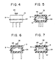
- a contact type of switch 37 is illustrated, an electrostatic capacity type as shown in Fig. 4, a diffused resistor type as shown in Fig. 5, a pressure sensitive rubber type as shown in Fig. 6, or a strain gauge type as shown in Fig. 7 may be also employed.
- the aforesaid types can be selectively combined.
- a slow type diaphragm or the like can be employed as the diaphragm 18 of the pressure receiving portion A.
- reference numeral 45 represents an electrode which also serves as a plunger.
- Reference numeral 46 represents a silicon substrate, and reference numeral 47 represents an electric circuit.
- Reference numeral 48 represents a pressure sensitive rubber.
- Reference numeral 49 represents a thin film
- reference numeral 50 represents a strain gauge.
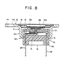
- a pressure sensor shown in Figs. 8 and 9 comprises, like the pressure sensor shown in Figs. 1 to 3, the pressure receiving portion A and the main sensor body B. However, the pressure receiving case 12 of the pressure receiving portion A is inserted into the switch case 13 of the main sensor body B.
- the end portion of the opening portion of the cylindrical case portion 12a of the pressure receiving case 12 is inwardly bent and projected to form an inserted portion 12b.
- this pressure receiving case 12 is inserted via the end portion of the opening portion of the cylindrical case portion 12a.
- the terminals 25 and 26 are press-fitted into the switch base 13a into which the pressure receiving case 1 has been inserted. Then, the cover 13b is mounted and the plunger 29 is inserted so as to form the completed main sensor body B.
- the pressure receiving portion A is assembled.
- the diaphragm 18 and the protection cap 16 are put on the pressure receiving flange 14 and their joints are welded together so as to form the completed pressure sensor.
- Figs. 10 and 11 illustrate the seventh embodiment of the present invention.
- the movable contact member 31 is made of a very thin electroconductive spring material.
- the base portion of the movable contact member 31 is connected to the upper edge of the first lead terminal 25 to serve as a supporting point.
- a free end 35 of the movable contact member 31 projects from the supporting point.
- the end portion 35 is arranged to contact the lower end of the plunger 29, while the upper surface of the intermediate portion of the projecting portion is arranged to be the movable contact 34.
- the movable contact 34 is formed to have a U-shaped cross section for improving its rigidity.
- the end of the movable contact 34 is secured to the top securing step 36 of the first lead terminal 25 for restricting the upward movement of the movable contact 34.
- the increased rigidity gives the movable contact 34 a high resistance to vibration. Therefore, more improved switch reliability can be obtained.
- the plunger 29 When the plunger 29 is positioned at its lower position, it pushes down the movable contact member 31, whereby the two contacts 33 and 34 are moved away from each other. As a result of this, the electric connection between the two lead terminals 25 and 26 is broken. On the other hand, when the plunger 29 is positioned at its upper position, the movable contact member 31 upwardly moves so as to bring the two contacts 33 and 34 into contact each other, whereby the two lead terminals 25 and 26 are connected.
- the movable contact 34 since the movable contact 34 has high rigidity, the deflection of the contact 34 can be kept small. As a result of this, stronger elastic force can be obtained at this intermediate position, whereby stable switching characteristics can be obtained.
- the switch portion 37 which is provided on the switch base 13 is operated by means of the diaphragm 18 which can be inversely displaced in accordance with any change in the fluid pressure, such as a gas pressure.
- the gap between the small contacts 33 and 34 which vertically oppose each other can be adjusted by means of an adjusting screw 38 so as to make it suitable for switching.
- a slit 39 is formed in the external edge of the connecting flange 24 for introducing air.
- the slit 29 forms part of an air passage 40 through which air is introduced or exhaled. Consequently, the slit 39 causes the diaphragm 18 to be easily operated in a transformation manner.
- the inversely moving portion 18a of the diaphragm 18 transforms to form an arc.
- the plunger 29 which is pressed by the transformed surface pushes down the movable contact member 31, whereby the two contacts 33 and 34 are moved away from each other. Consequently, a predetermined pressure is detected.
- the contacting pressure can be concentrated on that position, whereby precise and stable switching characteristics can be obtained.
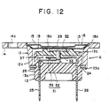
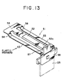
- a movable contact member 51 as shown in Fig. 12 in an enlarged manner, includes a rigid body 52 which is bent in a U-shape and disposed at the central portion, while elastic portions 53 and 53 for spring actin are disposed on both sides. These two portions 52 and 53 are integrally formed via the free end connection portion 54 and the base connecting portion 55.
- This movable contact member 51 is an electroconductive contacting member.
- steps 56 and 56 between the free end connection portion 54 and the elastic portions 53 and 53 the two elastic members 53 and 53 are formed in such a manner that the distance between the members 53 and the fixed contact member 33 is greater than that between the rigid body 52 and the contact member 33.
- a base end 52a of the rigid body 52 is fitted into a V-shaped groove 57 disposed in the upper portion of the terminal 25.
- the base connecting portion 55 is bent to form a L-shape and is secured to the backside of the terminal 25 via the L-shaped portion.
- the sensor main body B is inserted into the pressure receiving case 12 of the pressure receiving portion A and the retaining plate 24 is engaged with the thin cylindrical step 23.
- the lower end of the step 23 is partially, for example, at three equally spaced portions 23a disposed at an angle of 120°, deformed to fix the two portions of A and B.
- the top portion 32 of the plunger 29 is brought into contact with the diaphragm 18 by the elastic force of the movable contact member 31.
- the plunger 29 is moved vertically by the inverse movement of the diaphragm 18 in accordance with the change in the gas pressure, whereby the switch 37 is operated.
- the switch case 13 can be fixed to the pressure receiving case 12 by means of the deformed portions 23a which are disposed at the edges of the step 23, the following advantages can be obtained: the switch case 13 can be protected from heat conductance, which occurs in the conventional securing method in which the conventional welding is employed. Therefore, the switch case 13 can be protected from thermal deformation and the diaphragm 18 from deteriorating in performance.
- the productivity of the sensors according to the present invention can be improved.
- step 23 is deformed partially at the portions 23a, mechanical strain caused by deforming the portions 23a is so small that the diaphragm 18 can be protected from being deformed.
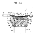
- Fig. 14 illustrates a ninth embodiment of the present invention in which the connecting flange 24 is provided with a slit 39 for introducing air between the switch base 13 and the case 21.
- the slit 39 communicates with an air passage 40 which is provided between the outer surface of the switch base 13 and the inner surface of the pressure receiving case 12.
- the upper surface of the diaphragm 18 receives fluid pressures while the lower surface thereof receives atmospheric pressures, whereby the transformation of the diaphragm 18 is allowed.
- Fig. 15 illustrates the tenth embodiment of the present invention.
- the air passage 13a is vertically formed through the switch base 13, whereby air can be introduced into the pressure sensor through the passage 13a. Even if this air passage 13 is provided, dust or water drops do not easily invade the sensor. Even if they invade, they can be stopped by the plunger 29, whereby the switch contacting portion which is disposed inside can be prevented from deterioration becasue of the dust or water drops. As a result of this, the reliability is improved.
- the other structures are the same as those shown in Figs. 1 and 2.
- the inversing portion 18a fo the diaphragm 18 is transformed in an arc shape, and pushes down the plunger 29.
- the plunger 29 downwardly presses the movable contact 31, whereby the two contacts 33 and 34 are moved away from each other. As a result of this, a predetermined fluid pressure is detected.
- the length between the outer surface of the switch base 13 and the switch portion 37 is long and the plunger 29 closes the switch portion 37 during the switch-on state. Therefore, when the diaphragm 18 is moved inversely, that is, when air is introduced, even if dust or water drops are introduced together through the air passage 13a from the outside, the introduced dust or water drops are prevented from being introduced to the switch contacting portion which is disposed inside of the device. As a result of this, the switch contacting portion can be protected against deleterious influences, whereby a reliable switch can be achieved.
- the water can be easily removed because it can evaporate through the air passage, and a filter which causes air flow resistance to be increased is not used, high-speed response of the switch can be achieved, and error in the switch operation can be also prevented.
Landscapes
- Physics & Mathematics (AREA)
- Fluid Mechanics (AREA)
- Switches Operated By Changes In Physical Conditions (AREA)
- Measuring Fluid Pressure (AREA)
Applications Claiming Priority (10)
| Application Number | Priority Date | Filing Date | Title |
|---|---|---|---|
| JP198012/86U | 1986-12-22 | ||
| JP1986198012U JPH0439635Y2 (de) | 1986-12-22 | 1986-12-22 | |
| JP198086/86U | 1986-12-23 | ||
| JP1986198086U JPH0439634Y2 (de) | 1986-12-23 | 1986-12-23 | |
| JP307512/86 | 1986-12-23 | ||
| JP30751286A JPS63160125A (ja) | 1986-12-23 | 1986-12-23 | 圧力センサ |
| JP117706/87U | 1987-07-30 | ||
| JP11770687U JPS63102139U (de) | 1987-07-30 | 1987-07-30 | |
| JP11828387U JPS6423846U (de) | 1987-08-01 | 1987-08-01 | |
| JP118283/87U | 1987-08-01 |
Publications (2)
| Publication Number | Publication Date |
|---|---|
| EP0276467A2 true EP0276467A2 (de) | 1988-08-03 |
| EP0276467A3 EP0276467A3 (de) | 1989-12-20 |
Family
ID=27526777
Family Applications (1)
| Application Number | Title | Priority Date | Filing Date |
|---|---|---|---|
| EP87119042A Withdrawn EP0276467A3 (de) | 1986-12-22 | 1987-12-22 | Druckwandler und dazugehöriger Schalter |
Country Status (2)
| Country | Link |
|---|---|
| US (2) | US4845322A (de) |
| EP (1) | EP0276467A3 (de) |
Families Citing this family (7)
| Publication number | Priority date | Publication date | Assignee | Title |
|---|---|---|---|---|
| US5198631A (en) * | 1991-09-11 | 1993-03-30 | General Electric Company | Pressure responsive control device |
| JP2000243196A (ja) * | 1999-02-17 | 2000-09-08 | Fuji Koki Corp | 圧力スイッチ |
| US6343414B1 (en) * | 1999-09-22 | 2002-02-05 | General Electric Company | Snap-disk formation process and machine |
| US8591198B2 (en) | 2007-05-22 | 2013-11-26 | Metropolitan Industries, Inc. | Strain gauge pump control switch |
| US8173918B2 (en) * | 2007-05-29 | 2012-05-08 | Norgren Gmbh | Pressure switch with an integrated diaphragm and switch |
| KR102637239B1 (ko) * | 2017-02-27 | 2024-02-19 | 현대모비스 주식회사 | 차량용 압력감지장치 |
| CN107024313B (zh) * | 2017-05-26 | 2023-02-17 | 苏州经贸职业技术学院 | 一种机械电子双显示的流体监测开关装置 |
Family Cites Families (14)
| Publication number | Priority date | Publication date | Assignee | Title |
|---|---|---|---|---|
| US3444341A (en) * | 1961-02-23 | 1969-05-13 | Perceptimus J Mighton | Pressure actuated switch |
| DE1590480A1 (de) * | 1965-10-14 | 1970-07-30 | Scheuffele & Co Robert | Druckschalter |
| US3890477A (en) * | 1973-05-18 | 1975-06-17 | Maytag Co | Control device |
| US3983351A (en) * | 1973-12-27 | 1976-09-28 | Robertshaw Controls Company | Electrical switch construction and method of making the same |
| US3963889A (en) * | 1974-07-30 | 1976-06-15 | International Telephone And Telegraph Corporation | Low velocity flow switch |
| US4202081A (en) * | 1976-06-07 | 1980-05-13 | Borg Instruments, Inc. | Method of assembling a pressure sensor |
| US4195209A (en) * | 1978-07-24 | 1980-03-25 | Emerson Electric Co. | Pressure responsive electrical switch and means of contact gap setting therefor |
| US4272660A (en) * | 1979-07-11 | 1981-06-09 | Stewart-Warner Corporation | Vacuum operated switch |
| US4328406A (en) * | 1979-08-02 | 1982-05-04 | Texas Instruments Incorporated | Condition responsive electrical switch and method of making |
| US4638721A (en) * | 1980-07-24 | 1987-01-27 | Texas Instruments Incorporated | Pressure responsive device |
| US4464551A (en) * | 1982-05-14 | 1984-08-07 | General Electric Company | Electric circuit controlling device and method of operating same |
| US4458117A (en) * | 1982-08-25 | 1984-07-03 | General Electric Company | Control device and methods of operating such |
| JPS612221A (ja) * | 1984-06-14 | 1986-01-08 | 本田技研工業株式会社 | 圧力スイツチ |
| US4573398A (en) * | 1984-11-05 | 1986-03-04 | Ranco Incorporated | Pressure control device and method of making the same |
-
1987
- 1987-12-22 EP EP87119042A patent/EP0276467A3/de not_active Withdrawn
- 1987-12-22 US US07/136,623 patent/US4845322A/en not_active Expired - Fee Related
-
1989
- 1989-03-22 US US07/327,102 patent/US4947544A/en not_active Expired - Lifetime
Also Published As
| Publication number | Publication date |
|---|---|
| US4947544A (en) | 1990-08-14 |
| EP0276467A3 (de) | 1989-12-20 |
| US4845322A (en) | 1989-07-04 |
Similar Documents
| Publication | Publication Date | Title |
|---|---|---|
| US5567874A (en) | Rotary position detecting device | |
| US4873871A (en) | Mechanical field effect transistor sensor | |
| US4616114A (en) | Pressure responsive switch having little or no differential between actuation release pressure levels | |
| US20170074737A1 (en) | Capacitance-Detection Type Pressure Switch and Pressure Sensor | |
| WO1994004897A1 (en) | Pressure transducer | |
| US4845322A (en) | Plunger type fluid pressure switch | |
| US20250118512A1 (en) | Temperature-dependent switch | |
| WO2005029057A1 (ja) | センサおよびセンサの製造方法 | |
| US5015808A (en) | Normally open pressure switch | |
| EP1548775B1 (de) | Membran für einen schlüsselschalter und schlüsselschalter | |
| EP0734036B1 (de) | Hochdruckschaltgerät | |
| US12360009B2 (en) | Gas sensor | |
| JP2883623B2 (ja) | 改善された寿命及び静止接点配置の広い公差を有する圧力応答スイッチ装置 | |
| US4633579A (en) | Method for making a pressure responsive switch | |
| CA1124289A (en) | Snap disc operated pressure switch | |
| CN119124418A (zh) | 力传感器、电子机械制动系统及汽车 | |
| CN2234612Y (zh) | 压力传感器 | |
| US5889247A (en) | Normally closed, pressure responsive electrical switch | |
| US4238651A (en) | Snap action fluid pressure switch | |
| EP0177035B1 (de) | Druckempfindlicher Schalter | |
| US4933517A (en) | Pressure switch with reduced contact wear | |
| JP3801007B2 (ja) | 重量センサ及びその製造方法 | |
| JP2893622B2 (ja) | 圧力スイッチおよびガスメータ | |
| US12242675B2 (en) | Multi-way input device | |
| US12031535B2 (en) | Compressor |
Legal Events
| Date | Code | Title | Description |
|---|---|---|---|
| PUAI | Public reference made under article 153(3) epc to a published international application that has entered the european phase |
Free format text: ORIGINAL CODE: 0009012 |
|
| 17P | Request for examination filed |
Effective date: 19871222 |
|
| AK | Designated contracting states |
Kind code of ref document: A2 Designated state(s): AT BE CH DE ES FR GB GR IT LI LU NL SE |
|
| PUAL | Search report despatched |
Free format text: ORIGINAL CODE: 0009013 |
|
| AK | Designated contracting states |
Kind code of ref document: A3 Designated state(s): AT BE CH DE ES FR GB GR IT LI LU NL SE |
|
| 17Q | First examination report despatched |
Effective date: 19911108 |
|
| STAA | Information on the status of an ep patent application or granted ep patent |
Free format text: STATUS: THE APPLICATION IS DEEMED TO BE WITHDRAWN |
|
| 18D | Application deemed to be withdrawn |
Effective date: 19921223 |