EP0276855A2 - Appareil duplicateur d'images - Google Patents
Appareil duplicateur d'images Download PDFInfo
- Publication number
- EP0276855A2 EP0276855A2 EP88101244A EP88101244A EP0276855A2 EP 0276855 A2 EP0276855 A2 EP 0276855A2 EP 88101244 A EP88101244 A EP 88101244A EP 88101244 A EP88101244 A EP 88101244A EP 0276855 A2 EP0276855 A2 EP 0276855A2
- Authority
- EP
- European Patent Office
- Prior art keywords
- mode
- control means
- modes
- switch
- selecting
- Prior art date
- Legal status (The legal status is an assumption and is not a legal conclusion. Google has not performed a legal analysis and makes no representation as to the accuracy of the status listed.)
- Withdrawn
Links
- 230000009467 reduction Effects 0.000 claims description 22
- 238000006722 reduction reaction Methods 0.000 claims 20
- 230000000994 depressogenic effect Effects 0.000 description 60
- 230000002093 peripheral effect Effects 0.000 description 11
- 238000004364 calculation method Methods 0.000 description 10
- 239000002245 particle Substances 0.000 description 10
- 239000003086 colorant Substances 0.000 description 6
- 230000003287 optical effect Effects 0.000 description 6
- 238000005286 illumination Methods 0.000 description 4
- 230000007246 mechanism Effects 0.000 description 4
- 230000001143 conditioned effect Effects 0.000 description 3
- 230000004048 modification Effects 0.000 description 3
- 238000012986 modification Methods 0.000 description 3
- 230000002457 bidirectional effect Effects 0.000 description 2
- 230000008859 change Effects 0.000 description 2
- 238000010276 construction Methods 0.000 description 2
- 230000000694 effects Effects 0.000 description 2
- 230000002452 interceptive effect Effects 0.000 description 2
- 238000000034 method Methods 0.000 description 2
- 230000008569 process Effects 0.000 description 2
- 238000007792 addition Methods 0.000 description 1
- 230000005540 biological transmission Effects 0.000 description 1
- 238000004891 communication Methods 0.000 description 1
- 238000010586 diagram Methods 0.000 description 1
- 238000004519 manufacturing process Methods 0.000 description 1
- 239000000203 mixture Substances 0.000 description 1
- 239000000843 powder Substances 0.000 description 1
- 230000002441 reversible effect Effects 0.000 description 1
- 238000000926 separation method Methods 0.000 description 1
- 239000007787 solid Substances 0.000 description 1
- 230000001360 synchronised effect Effects 0.000 description 1
- 230000000007 visual effect Effects 0.000 description 1
Images


Classifications
-
- G—PHYSICS
- G03—PHOTOGRAPHY; CINEMATOGRAPHY; ANALOGOUS TECHNIQUES USING WAVES OTHER THAN OPTICAL WAVES; ELECTROGRAPHY; HOLOGRAPHY
- G03G—ELECTROGRAPHY; ELECTROPHOTOGRAPHY; MAGNETOGRAPHY
- G03G15/00—Apparatus for electrographic processes using a charge pattern
- G03G15/50—Machine control of apparatus for electrographic processes using a charge pattern, e.g. regulating differents parts of the machine, multimode copiers, microprocessor control
- G03G15/5016—User-machine interface; Display panels; Control console
Definitions
- the present invention relates to an image duplicating apparatus and particularly to an electrophotographic image duplicating apparatus such as a copying apparatus of the type having an interactive control panel or an interactive section in a control panel.
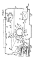
- an image duplicating apparatus (here strictlyinafter referred to simply as copying apparatus) embodying the present invention comprises a housing 20 having an upper panel portion formed in part by a transparent document table 22. A sheet of document (not shown) bearing images to be reproduced is to be placed on this document table 22.
- drum cleaner unit 60 which removes any residual toner particles from the peripheral surface of the drum 50.
- a charge eraser lamp 62 which irradiates the cleaned peripheral surface of the drum 50 to eliminate the charges which may be left thereon.
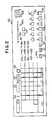
- control panel 100 Further provided on the control panel 100 are print density increment and decrement switches 116 with respectively associated indicators 116 a to permit manual selection of a desired print density for the copy sheets to be printed.
- the print density is stepwise incremented with one of the switches 116 depressed or decremented with the other of the switches 116 depressed.
- the color of the imaged to be printed can be selected from among different available colors at a color select switch 118 (CL) having associated color indicators 118 a , 118 b and 118 c allocated to different print colors such as black, red (or magenta) and yellow, respectively.
- the color select switch 118 is in effect operative to select one or two of the developing units 54 a and 54 b of the image developing stage 54 of the apparatus shown in Fig. 1.
- zoom switches 120 On the control panel 100 are further provided zoom switches 120 for continuously varying the coordinate values or magnification ratio entered for edited mode of copying operation.
- the numerical data continuously selected by the switches 120 are displayed on a magn
- the charges are caused to dissipate on the area of the drum surface as defined by the four coordinate points given by the x-coordinates X1 and X2 and the y-coordinates Y1 and Y2. There can thus be produced no latent images within this area when the drum 50 is illuminated with an information carrying beam incident on the drum surface.
- the area is displayed as the edited copy/erase area R on the display screen 316 shown in Fig. 4.
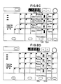
- the first strip 350 a form the switch areas 324 a , 328 a , 330 a 334 a 336 a 340 a and 344 a arranged in a first row of the subsections 300, 302, 304, 306 and 408.
- the second switch strip 350 b form the switch areas 324 b 328 b , 330 b , 334 b , 336 b , 340 b and 344 b arranged in a second row of the subsections 300, 302, 304, 306 and 408.
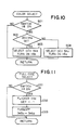
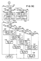
- step D14 If it is found at the step D12 that there is no signal produced with the second switch strip 350 b depressed in the touch panel section 124, it is further tested at a step D14 whether or not there is present a signal produced with the third switch strip 350 c depressed in the touch panel section 124. In the presence of such a signal, the step D14 is followed by a step D15 at which the status flag F ZS is shifted to logic "0" state and an instruction signal is issued so that only the indicator 345 c associated with the switch area 344 c is turned on to flicker with all the other indicators 345 a , 345 b and 345 d for the switch areas 344 a , 344 b and 344 d turned off in the subsection 308. At this step D15 is further issued an instruction signal to drive the lens unit 42 to move to a position providing a third predetermined magnification ratio memorized in the magnification memory area selected from the switch area 344 c .
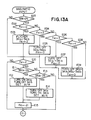
- step E04 If it is found at the step E04 that the status flag F ZI is not of the "2" state, it is tested at a step E06 whether or not the status flag F ZI is of a "3" state. If it is found that the status flag F ZI is of the "3" state, the step E06 is followed by a step E07 at which the status flag F ZI is shifted to the "0" state and an instruction signal is issued so that the indicators 341 a to 341 d respectively associated with all the switch areas 340 a to 340 d in the subsection 306 are turned off.
- the step E34 is followed by a step E35 at which an instruction signal is further issued to drive the lens unit 42 for movement to a position providing the corrected magnification ratio while memorizing the magnification ratio into the selected memory area and shifting the status flag F ZS to the "0" state. If it is found at the step E33 that there is no signal produced with the second switch strip 350 c depressed, it is further tested at a step E36 whether or not there is present a signal produced with the fourth switch strip 350 d depressed. In the presence of such a signal, the step E36 is followed by a step E37 at which an instruction signal is issued so that only the indicator 345 d associated with the switch area 344 d is turned on to flicker.
- an instruction signal is issued at a step F05 by which the indicators 118 a and 118 b allocated to the developing units 54 a and 54 b storing the black and red colored toners are turned on to flicker.
- the step F05 is followed by a step F06 by which an instruction signal is further issued so that the indicators 325 a , 325 b and 325 c respectively associated with the black select switch 324 a , area color switch 324 b and area erase switch 324 c are turned on to flicker.
- an instruction signal is issued at a step F12 by which the indicators 118 a and 118 b allocated to the developing units 54 a and 54 b storing the black and red colored toners are turned on to flicker.
- the step F12 is followed by a step F13 by which an instruction signal is further issued so that the indicators 325 a , 325 b and 325 c respectively associated with the black select switch 324 a , area color switch 324 b and area erase switch 324 c are turned on to flicker.
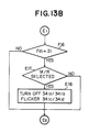
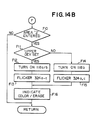
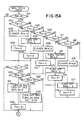
- the status flag F ZI is shifted to a "21" state at a step G24, whereupon it is confirmed at a step G25 shown in Fig. 15B whether or not the status flag F ZI is of the "3" state. If it is found that the status flag F ZI is of the "3" state, the step G25 is followed by a step G26 at which it is queried whether or not there is present a signal produced with the third switch strip 350 c depressed in the touch panel section 124.
- step G26 If it is found at the step G26 that there is no signal produced with the third switch strip 350 c depressed, it is queried at a step G29 whether or not there is present a signal produced with the fourth switch strip 350 d depressed in the touch panel section 124. In the presence of such a signal, an instruction signal is issued at a step G30 so that the indicator 341 c associated with the switch area 340 c is turned off and the indicator 341 d for the switch area 340 d turned on to flicker in the fourth subsection 306 of the touch panel section 124.
Landscapes
- Engineering & Computer Science (AREA)
- Microelectronics & Electronic Packaging (AREA)
- Physics & Mathematics (AREA)
- General Physics & Mathematics (AREA)
- Control Or Security For Electrophotography (AREA)
- Facsimiles In General (AREA)
- Accessory Devices And Overall Control Thereof (AREA)
Applications Claiming Priority (16)
| Application Number | Priority Date | Filing Date | Title |
|---|---|---|---|
| JP1885387 | 1987-01-28 | ||
| JP62018851A JPS63186264A (ja) | 1987-01-28 | 1987-01-28 | 複写機能選択装置 |
| JP62018850A JPS63186263A (ja) | 1987-01-28 | 1987-01-28 | 複写機能選択装置 |
| JP18849/87 | 1987-01-28 | ||
| JP62018852A JPS63186265A (ja) | 1987-01-28 | 1987-01-28 | 複写機能選択装置 |
| JP18850/87 | 1987-01-28 | ||
| JP62018849A JPS63186262A (ja) | 1987-01-28 | 1987-01-28 | 複写機能選択装置 |
| JP18853/87 | 1987-01-28 | ||
| JP18852/87 | 1987-01-28 | ||
| JP18851/87 | 1987-01-28 | ||
| JP62139515A JPS63301973A (ja) | 1987-06-02 | 1987-06-02 | 対話操作型操作パネルの制御方式 |
| JP139515/87 | 1987-06-02 | ||
| JP62143557A JPS63306466A (ja) | 1987-06-08 | 1987-06-08 | 対話操作パネルにおける機能設定方式 |
| JP62143558A JPS63306467A (ja) | 1987-06-08 | 1987-06-08 | 複写倍率設定方式 |
| JP143557/87 | 1987-06-08 | ||
| JP143558/87 | 1987-06-08 |
Publications (2)
| Publication Number | Publication Date |
|---|---|
| EP0276855A2 true EP0276855A2 (fr) | 1988-08-03 |
| EP0276855A3 EP0276855A3 (fr) | 1990-06-20 |
Family
ID=27571856
Family Applications (1)
| Application Number | Title | Priority Date | Filing Date |
|---|---|---|---|
| EP88101244A Withdrawn EP0276855A3 (fr) | 1987-01-28 | 1988-01-28 | Appareil duplicateur d'images |
Country Status (1)
| Country | Link |
|---|---|
| EP (1) | EP0276855A3 (fr) |
Cited By (1)
| Publication number | Priority date | Publication date | Assignee | Title |
|---|---|---|---|---|
| EP0321932B1 (fr) * | 1987-12-21 | 1994-07-20 | Sharp Kabushiki Kaisha | Appareil de formation d'images avec plusieurs fonctions de traitement d'image |
Family Cites Families (2)
| Publication number | Priority date | Publication date | Assignee | Title |
|---|---|---|---|---|
| JPS60136760A (ja) * | 1983-12-26 | 1985-07-20 | Minolta Camera Co Ltd | 複写機 |
| US4758866A (en) * | 1985-07-09 | 1988-07-19 | Minolta Camera Kabushiki Kaisha | Copying apparatus |
-
1988
- 1988-01-28 EP EP88101244A patent/EP0276855A3/fr not_active Withdrawn
Cited By (1)
| Publication number | Priority date | Publication date | Assignee | Title |
|---|---|---|---|---|
| EP0321932B1 (fr) * | 1987-12-21 | 1994-07-20 | Sharp Kabushiki Kaisha | Appareil de formation d'images avec plusieurs fonctions de traitement d'image |
Also Published As
| Publication number | Publication date |
|---|---|
| EP0276855A3 (fr) | 1990-06-20 |
Similar Documents
| Publication | Publication Date | Title |
|---|---|---|
| US4814824A (en) | Image duplicating apparatus | |
| US4582417A (en) | Apparatus for forming images | |
| US4794421A (en) | Apparatus and method for electrophotographically producing copies from originals having continuous-tone and other content | |
| US4701044A (en) | Image recording apparatus for composing plural partial original images into a single composite image | |
| US4984020A (en) | Copying apparatus having an area designating function | |
| JPH0731360B2 (ja) | 部分複写の機能を備えた複写装置 | |
| EP0127867B1 (fr) | Appareil de formation d'image | |
| US4745443A (en) | Copying apparatus | |
| EP0276855A2 (fr) | Appareil duplicateur d'images | |
| EP0297177B1 (fr) | Appareil pour copier des images | |
| US5049933A (en) | Image edit input device for use in copying machine | |
| JPH0619603B2 (ja) | 複写装置 | |
| US5083162A (en) | Image duplicating apparatus including an editing function | |
| US5134437A (en) | Image duplicating apparatus having multiple editing capacity | |
| US5008714A (en) | Image forming apparatus having an automatic document feed device for automatically discharging a manually positioned document | |
| US5459554A (en) | Image-forming apparatus for forming an image at a plurality of image-forming conditions | |
| US5278611A (en) | Image duplicating apparatus for use with an external data storage medium | |
| US5073794A (en) | Image duplicating apparatus in which user specified operational conditions are stored and used based on the detected nature of the document being copied | |
| US4849789A (en) | Image duplicating apparatus for multiple images with magnification or reduction alteration during duplication | |
| US4958190A (en) | Image forming apparatus | |
| JPS613159A (ja) | 画像編集複写機 | |
| US4888615A (en) | Image forming apparatus for selective copying of segmented areas of an image | |
| JPS613157A (ja) | 画像編集複写機 | |
| JPS613182A (ja) | 画像編集複写機 | |
| JPS613180A (ja) | 画像編集複写機 |
Legal Events
| Date | Code | Title | Description |
|---|---|---|---|
| PUAI | Public reference made under article 153(3) epc to a published international application that has entered the european phase |
Free format text: ORIGINAL CODE: 0009012 |
|
| AK | Designated contracting states |
Kind code of ref document: A2 Designated state(s): DE FR GB |
|
| PUAL | Search report despatched |
Free format text: ORIGINAL CODE: 0009013 |
|
| AK | Designated contracting states |
Kind code of ref document: A3 Designated state(s): DE FR GB |
|
| 17P | Request for examination filed |
Effective date: 19900828 |
|
| 17Q | First examination report despatched |
Effective date: 19920225 |
|
| STAA | Information on the status of an ep patent application or granted ep patent |
Free format text: STATUS: THE APPLICATION HAS BEEN WITHDRAWN |
|
| 18W | Application withdrawn |
Withdrawal date: 19930201 |