EP0277249B1 - Dispositif de serrage de moule pour une machine de moulage a injection - Google Patents
Dispositif de serrage de moule pour une machine de moulage a injection Download PDFInfo
- Publication number
- EP0277249B1 EP0277249B1 EP87904969A EP87904969A EP0277249B1 EP 0277249 B1 EP0277249 B1 EP 0277249B1 EP 87904969 A EP87904969 A EP 87904969A EP 87904969 A EP87904969 A EP 87904969A EP 0277249 B1 EP0277249 B1 EP 0277249B1
- Authority
- EP
- European Patent Office
- Prior art keywords
- mold clamping
- motors
- servomotors
- driven
- clamping apparatus
- Prior art date
- Legal status (The legal status is an assumption and is not a legal conclusion. Google has not performed a legal analysis and makes no representation as to the accuracy of the status listed.)
- Expired - Lifetime
Links
- 238000001746 injection moulding Methods 0.000 title claims abstract description 10
- 238000004804 winding Methods 0.000 claims description 9
- 230000008878 coupling Effects 0.000 claims description 6
- 238000010168 coupling process Methods 0.000 claims description 6
- 238000005859 coupling reaction Methods 0.000 claims description 6
- 230000005540 biological transmission Effects 0.000 description 2
- 230000001360 synchronised effect Effects 0.000 description 2
- 230000001133 acceleration Effects 0.000 description 1
- 238000010586 diagram Methods 0.000 description 1
Images


Classifications
-
- B—PERFORMING OPERATIONS; TRANSPORTING
- B29—WORKING OF PLASTICS; WORKING OF SUBSTANCES IN A PLASTIC STATE IN GENERAL
- B29C—SHAPING OR JOINING OF PLASTICS; SHAPING OF MATERIAL IN A PLASTIC STATE, NOT OTHERWISE PROVIDED FOR; AFTER-TREATMENT OF THE SHAPED PRODUCTS, e.g. REPAIRING
- B29C45/00—Injection moulding, i.e. forcing the required volume of moulding material through a nozzle into a closed mould; Apparatus therefor
- B29C45/17—Component parts, details or accessories; Auxiliary operations
- B29C45/64—Mould opening, closing or clamping devices
-
- B—PERFORMING OPERATIONS; TRANSPORTING
- B29—WORKING OF PLASTICS; WORKING OF SUBSTANCES IN A PLASTIC STATE IN GENERAL
- B29C—SHAPING OR JOINING OF PLASTICS; SHAPING OF MATERIAL IN A PLASTIC STATE, NOT OTHERWISE PROVIDED FOR; AFTER-TREATMENT OF THE SHAPED PRODUCTS, e.g. REPAIRING
- B29C45/00—Injection moulding, i.e. forcing the required volume of moulding material through a nozzle into a closed mould; Apparatus therefor
- B29C45/17—Component parts, details or accessories; Auxiliary operations
- B29C45/64—Mould opening, closing or clamping devices
- B29C45/66—Mould opening, closing or clamping devices mechanical
Definitions
- the present invention relates to a mold clamping apparatus for use in an injection molding machine, and more particularly to a spindle driving device in the mold clamping apparatus.
- a mold clamping apparatus of a type comprising a drive source consisting of an electric motor (hereinafter referred to as a motor), and a power transmission system for converting a turning force generated by the drive source into a driving force for axially driving a spindle.
- a movable platen is arranged to be movable in unison with the spindle and is thereby axially driven by the drive source through the power transmission system so as to perform mold-opening, mold-closing and mold-clamping.
- the drive source may consist of a single general-purpose motor capable of generating a required mold clamping force in the case of a small or medium apparatus where the required mold clamping force varies from 5 tons to 10 tons.
- the drive source in a large mold clamping apparatus requiring a larger mold clamping force, however, the drive source must be of a specially ordered high-output type. For this reason, a considerable cost increase occurs and further operational response of the motor is deteriorated since inertia of the rotor becomes large.
- JP-A 60 247 946 a mold clamping apparatus according to the preamble of the attached claim 1, wherein a first motor drives a movable die initially and then stops to be replaced in the driving function by a second motor which operates at low speed and high torque.
- a first motor drives a movable die initially and then stops to be replaced in the driving function by a second motor which operates at low speed and high torque.
- two driving systems are provided, one for high speed and the other for low speed and high torque.
- a mold clamping apparatus comprising a movable platen, a spindle operatively connected to drive the movable platen, a plurality of general-purpose motors for driving the spindle, and coupling means coupling the motors to the spindle, characterised in that the mold clamping apparatus is adapted for use in an injection molding machine controlled by a host control unit and comprises: detecting means for detecting at least one of a rotational position and a rotational speed of one of the motors, which are servomotors, and for producing an output signal indicative of said detected position and/or speed; a control circuit for generating a torque command signal in accordance with a difference between said output signal from said detecting means indicative of the detected position or speed, and a command signal from the host control unit; and driving circuits for driving corresponding respective ones of the servomotors in accordance with said torque command signal supplied from said control circuit, said driving circuits corresponding in number to that of said plurality of servomotors and being
- Embodiments of the present invention may provide a mold clamping apparatus in an injection molding machine, which is low in cost and has an improved response.
- a spindle driving device of the mold clamping apparatus may be low in cost.
- a rotor of each motor may be prevented from becoming large in diameter size, the sum of the rotor inertias of the plural motors can be less than that of a single special motor, and hence the operational response of the motors in particular the acceleration/deceleration characteristics thereof, can be improved.
- a conventional spindle driving device for use in a mold clamping apparatus of an injection molding machine will be explained.
- a ball screw 2 as a spindle is rotatably supported by a rear platen 1, and a ball nut 3 is threadedly engaged with an outer portion of the ball screw 2 projecting rearwardly of the rear platen 1.
- a timing pulley (hereinafter referred to as a pulley) 4 is coupled to the ball nut 3 in a manner rotatable integrally with the same nut. Further, the pulley 4 is operatively coupled to a servomotor 5 through a timing belt 7 which is wound around the pulley 4 and a second pulley 6 fixed to the output shaft of the motor 5.
- the ball screw 2 has its inner end coupled to a movable platen (not shown) through a crosshead (not shown) of the mold clamping apparatus (in case that the apparatus has a toggle mechanism) or coupled directly thereto (in the case of the direct-acting type clamping apparatus).
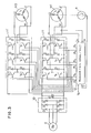
- a spindle driving device of a mold clamping apparatus for use in an injection molding machine will be explained with reference to Fig 1.
- this spindle driving device is constructed in the same manner as that shown in Fig. 2, parts common to Figs. 1 and 2 being shown by like reference numerals or symbols.
- Symbols M1 and M2 designate spindle driving motors which each consist of an AC servomotor consisting of a general-purpose permanent-magnet synchronous motor, respectively. These motors are fixed integrally to the rear platen 1 by means of an appropriate means, not shown, and have their output shafts to which drive pulleys 8 and 9 are fixed, respectively. Further, a driven pulley 4 is fixed to a ball nut 3 which is threadedly engaged with a ball screw 2 as the single spindle of the mold clamping apparatus. The motors M1, M2 are operatively coupled to the ball nut 3 through the pulleys 4, 8 and 9 and a timing belt 7 wound around these pulleys.
- the mold clamping device in order to produce, from the two general-purpose motors M1 and M2, the combined output equivalent to that of a single high-output type motor, the mold clamping device according to this embodiment is arranged to drive these motors so that the motors M1, M2 are driven in synchronism with each other to produce their output torque acting in the same rotational direction.
- a control unit is provided, which has a control circuit responsive to a position/speed signal associated with one of the motors, the motor M1, for instance, and two motor driving circuits for these motors M1 and M2, the control unit being arranged to deliver the same drive current command from its control circuit to both of the motor drive circuits.
- this control uint is constructed in the same manner as a conventional PWM control unit known as a servomotor driving control unit, but differs from the conventional one in that two transistor inverters as power amplifiers are provided, these inverters being connected in parallel with each other.
- reference symbol E designates a three-phase power source
- numeral 10 denotes a rectifier
- 11 a transistor inverter, as a power amplifier, which generates an output for driving the servomotor M1.
- An ordinary PWM control unit has this transistor inverter 11 alone by which a single servomotor is driven.
- a further transistor inverter 11' is connected in parallel with the transistor inverter 11 and is arranged to drive a corresponding servomotor M2.
- Reference numeral 12 denotes a transistor PWM control circuit, and symbol P designates the position detector, such as a pulse encoder, for detecting the position and speed of a rotor of the servomotor M1.
- the transistor PWM control circuit 12 is arranged to compare a present speed S, detected by the position detector P, with a speed command V0 from a host control unit such as an NC, to turn on-off transistors TA to TF and TA' to TF' of the transistor inverters 11 and 11', so as to control currents flowing through the U-, V-, and W-phase windings of the servomotors M1 and M2, thereby controlling the rotating speed of the servomotors M1 and M2.
- a host control unit such as an NC
- the transistors TA and TA' and the transistors TB and TB' of the transistor inverters 11 and 11' are simultaneously turned on or off, whereby the currents flowing through the respective U-phase windings of the servomotors M1 and M2 are controlled.
- the transistors TC, TC' and the transistors TD, TD' are simultaneously turned on or off, whereby the currents flowing through the respective V-phase windings of the servomotors M1, M2 are controlled.
- the transistors TE, TE' and the transistors TF, TF' are simultaneously turned on or off, whereby the currents flowing through the respective W-phase windings of the servomotors M1, M2 are controlled.
- the servomotors M1 and M2 are driven in synchronism with each other so as to produce the same torque.
- a detailed description of the transistor PWM control circuit 12, which is a conventional one, is omitted herein.
- the circuit 12 compares the speed command value V0 with the present speed S detected by the position detector P. In accordance with the difference between the value V0 and the speed S, the control circuit 12 delivers the PWM signals PA to PF, and causes the transistor inverters 11 and 11' to drive the servomotors M1 and M2, so as to control the motor speeds to a command speed.
- the transistors associated with the corresponding phases of the transistor inverters 11, 11', serving to control the currents flowing throgh the windings of the individual phases of the servomotors M1 and M2, are turned on or off in accordance with the same PWM signal, so that one and the same current flows synchronously through the windings of each phase of the servomtors M1 and M2.
- the servomotors M1, M2 rotate in synchronism with each other, with the same output torque, to drive the timing belt 7.
- the two timing gear pulleys 8 and 9 are in engagement with the timing belt 7, respectively, no phase dislocation occurs between these timing gear pulleys.
- a gear train may be employed in place of the timing belt.
- more than two or three motors may be employed as distinct from the above-mentioned embodiment having two motors.
- an AC servomotor consisting of a permanent-magnetic synchronous motor is employed in the above-mentioned embodiment, a DC servomotor may be used.
- one or more additional power amplifiers alone should be provided in the servomotor control unit, while other control circuits and position detectors may be commonly employed.
Landscapes
- Engineering & Computer Science (AREA)
- Manufacturing & Machinery (AREA)
- Mechanical Engineering (AREA)
- Moulds For Moulding Plastics Or The Like (AREA)
- Injection Moulding Of Plastics Or The Like (AREA)
Abstract
Claims (4)
- Un dispositif de serrage de moule comprenant une platine mobile, une broche (2) reliée de manière opérationnelle pour entraîner la platine mobile, un ensemble de moteurs à fins multiples (M1, M2) pour entraîner la broche (2), et des moyens de couplage (3, 4, 7, 8, 9) reliant les moteurs (M1, M2) à la broche (2), caractérisé en ce que le dispositif de serrage de moule est prévu pour être utilisé dans une machine de moulage par injection commandée par une unité de commande centrale et comprend : des moyens de détection (P) pour détecter une position de rotation et/ou une vitesse de rotation de l'un des moteurs (M1, M2), lesquels sont des servomoteurs, et pour produire un signal de sortie (S) indicateur de ladite position et/ou vitesse détectée ; un circuit de commande (12) pour générer un signal d'ordre de couple en accord avec une différence entre ledit signal de sortie (S) provenant desdits moyens de détection (P) et indicateur de ladite position ou vitesse détectée, et un signal d'ordre (VO) provenant de l'unité de commande centrale ; et des circuits d'entraînement (11, 11') pour entraîner des servomoteurs respectifs correspondants (M1, M2) en accord avec ledit signal d'ordre de couple provenant dudit circuit de commande (12), lesdits circuits d'entraînement (11, 11') correspondant en nombre à celui dudit ensemble de servomoteurs (M1, M2) et étant montés pour entraîner les servomoteurs (M1, M2) simultanément de sorte qu'ils sont entraînés en synchronisme l'un avec l'autre pour fournir en sortie une puissance combinée équivalente à celle d'un moteur unique de plus grande puissance.
- Un dispositif de serrage de moule selon la revendication 1, dans lequel la broche (2) est une vis à bille, lesdits moyens de couplage comprenant un écrou à bille (3) en prise de filetage avec ce dernier.
- Un dispositif de serrage de moule selon la revendication 2, dans lequel lesdits moyens de couplage comprennent en outre une poulie menée à engrenage de synchronisation (4) montée pour pouvoir tourner conjointement avec ledit écrou à bille (3), un ensemble de poulies menantes à engrenage de synchronisation (8, 9) fixées aux arbres de sortie respectifs desdits moteurs (M1, M2) et une courroie de synchronisation (7) enroulée entre ladite poulie menée à engrenage de synchronisation (4) et ledit ensemble de poulies menantes à engrenage de synchronisation (8, 9).
- Un dispositif de serrage de moule selon une revendication précédente quelconque, dans lequel chacun desdits servomoteurs (M1, M2) présente des enroulements (U,V,W) de phases respectives et en ce que lesdits circuits d'entraînement (11, 11') présentent des éléments de commutation (TA à TF , TA' à TF') qui commandent respectivement des courants électriques circulant à travers les enroulements (U,V,W) des phases respectives desdits servomoteurs (M1, M2) et dans lequel ledit circuit de commande (12) effectue une commande marche-arrêt desdits éléments de commutation (TA à TF , TA' à TF') en accord avec la différence entre le signal de sortie (S) et le signal d'ordre (VO), de sorte que le même courant électrique circule à travers les enroulements respectifs (U,V,W) qui sont associés à la même phase lorsque le dispositif de serrage de moule est en fonctionnement.
Applications Claiming Priority (2)
| Application Number | Priority Date | Filing Date | Title |
|---|---|---|---|
| JP186967/86 | 1986-08-11 | ||
| JP61186967A JPS6342826A (ja) | 1986-08-11 | 1986-08-11 | 射出成形機における型締め装置 |
Publications (3)
| Publication Number | Publication Date |
|---|---|
| EP0277249A1 EP0277249A1 (fr) | 1988-08-10 |
| EP0277249A4 EP0277249A4 (fr) | 1989-10-24 |
| EP0277249B1 true EP0277249B1 (fr) | 1993-02-24 |
Family
ID=16197860
Family Applications (1)
| Application Number | Title | Priority Date | Filing Date |
|---|---|---|---|
| EP87904969A Expired - Lifetime EP0277249B1 (fr) | 1986-08-11 | 1987-07-31 | Dispositif de serrage de moule pour une machine de moulage a injection |
Country Status (6)
| Country | Link |
|---|---|
| US (1) | US4877388A (fr) |
| EP (1) | EP0277249B1 (fr) |
| JP (1) | JPS6342826A (fr) |
| KR (1) | KR910001569B1 (fr) |
| DE (1) | DE3784338T2 (fr) |
| WO (1) | WO1988001225A1 (fr) |
Cited By (1)
| Publication number | Priority date | Publication date | Assignee | Title |
|---|---|---|---|---|
| DE19514346C1 (de) * | 1995-04-18 | 1996-05-09 | Ferromatik Milacron Maschinenb | Vorrichtung zur Schmiermittelversorgung einer Spritzgießmaschine |
Families Citing this family (16)
| Publication number | Priority date | Publication date | Assignee | Title |
|---|---|---|---|---|
| USD318282S (en) | 1988-03-22 | 1991-07-16 | Fairchild Industries, Inc. | Clamp |
| JP2584287B2 (ja) * | 1988-08-29 | 1997-02-26 | ファナック株式会社 | トグル式型締装置 |
| US5102327A (en) * | 1989-11-06 | 1992-04-07 | Cincinnati Milacron Inc. | Mold clamping system |
| US4990084A (en) * | 1989-11-06 | 1991-02-05 | Cincinnati Milacron Inc. | Mold clamping system |
| US5190714A (en) * | 1989-11-06 | 1993-03-02 | Cincinnati Milacron Inc. | Mold clamping system |
| CH680916A5 (fr) * | 1989-11-10 | 1992-12-15 | Vickers Inc | |
| US5321341A (en) * | 1993-06-15 | 1994-06-14 | Captive Plastics, Inc. | Drive module for machine |
| US6149418A (en) * | 1999-04-16 | 2000-11-21 | Milacron Inc. | Dual motor drive system for an injection molding machine |
| JP2002101560A (ja) * | 2000-09-26 | 2002-04-05 | Honda Motor Co Ltd | 発電装置 |
| US7193826B2 (en) * | 2004-02-27 | 2007-03-20 | York International Corporation | Motor disconnect arrangement for a variable speed drive |
| US7164242B2 (en) * | 2004-02-27 | 2007-01-16 | York International Corp. | Variable speed drive for multiple loads |
| US7231773B2 (en) * | 2004-04-12 | 2007-06-19 | York International Corporation | Startup control system and method for a multiple compressor chiller system |
| US7793509B2 (en) | 2004-04-12 | 2010-09-14 | Johnson Controls Technology Company | System and method for capacity control in a multiple compressor chiller system |
| US7207183B2 (en) * | 2004-04-12 | 2007-04-24 | York International Corp. | System and method for capacity control in a multiple compressor chiller system |
| DE102005053802A1 (de) * | 2005-11-11 | 2007-05-16 | Demag Ergotech Gmbh | Schließvorrichtung für eine Spritzgießmaschine |
| JP5800938B2 (ja) * | 2014-03-19 | 2015-10-28 | ファナック株式会社 | 電源コンバータ制御部を有する射出成形機の制御装置 |
Family Cites Families (26)
| Publication number | Priority date | Publication date | Assignee | Title |
|---|---|---|---|---|
| US1313079A (en) * | 1919-08-12 | Electric ship propulsion | ||
| US3063708A (en) * | 1958-05-09 | 1962-11-13 | Honsberg Geb | Electro-mechanical clamping drive with electric control |
| DE1231883B (de) * | 1964-09-25 | 1967-01-05 | Fischbach Alfred | Spritzgiessmaschine fuer Kunststoffe |
| US3340748A (en) * | 1965-01-28 | 1967-09-12 | Unitwin Corp | Multi-engine drive mechanism |
| JPS5113495B1 (fr) * | 1968-07-05 | 1976-04-30 | ||
| JPS5172808A (ja) * | 1974-12-19 | 1976-06-24 | Mitsubishi Motors Corp | Nenpikeigengatajidoshayokudosochi |
| US4288727A (en) * | 1977-09-07 | 1981-09-08 | The Flinders University Of South Australia | Modular motor and control means and method |
| US4528483A (en) * | 1979-07-17 | 1985-07-09 | Papst Motoren Gmbh & Co. Kg | Multiple-shaft drive |
| US4260936A (en) * | 1979-08-02 | 1981-04-07 | Xerox Corporation | Master-slave power amplifiers |
| US4445167A (en) * | 1981-10-05 | 1984-04-24 | Tokyo Shibaura Denki Kabushiki Kaisha | Inverter system |
| JPS58130792A (ja) * | 1982-01-28 | 1983-08-04 | Fanuc Ltd | 同期電動機の駆動装置 |
| JPS5925038A (ja) * | 1982-08-02 | 1984-02-08 | Mitsubishi Heavy Ind Ltd | 並列ガスタ−ビン |
| US4525656A (en) * | 1982-08-24 | 1985-06-25 | Mitsubishi Denki Kabushiki Kaisha | Apparatus for operating plural poly phase A.C. motors having a common load |
| JPS59187826A (ja) * | 1983-04-08 | 1984-10-25 | Nissei Plastics Ind Co | 成形機の型締方法 |
| JPS6049853A (ja) * | 1983-08-27 | 1985-03-19 | Nissan Motor Co Ltd | 直圧式ダイキヤストマシンの型締め減速位置調整装置 |
| US4644232A (en) * | 1983-10-19 | 1987-02-17 | Hitachi, Ltd. | Method of and an apparatus for controlling a plurality of DC motors |
| JPS60125618A (ja) * | 1983-12-13 | 1985-07-04 | Fanuc Ltd | 射出成形機における射出機構駆動装置 |
| JPS60125619A (ja) * | 1983-12-13 | 1985-07-04 | Fanuc Ltd | 型締め装置 |
| JPS61125829A (ja) * | 1984-11-24 | 1986-06-13 | Fanuc Ltd | 射出成形機における型締方式 |
| JPS61160214A (ja) * | 1984-12-29 | 1986-07-19 | Toyoda Gosei Co Ltd | 射出成形機 |
| JPS61237615A (ja) * | 1985-04-15 | 1986-10-22 | Toshiba Mach Co Ltd | 射出スクリュの駆動装置 |
| JPS61244520A (ja) * | 1985-04-23 | 1986-10-30 | Toshiba Mach Co Ltd | 電動機駆動射出成形機 |
| US4614901A (en) * | 1985-10-15 | 1986-09-30 | Kennedy Company | Servo power amplifier having load equalization |
| JPS62128724A (ja) * | 1985-11-30 | 1987-06-11 | Fanuc Ltd | 射出駆動装置 |
| JPS635918A (ja) * | 1986-06-27 | 1988-01-11 | Fanuc Ltd | ラチエツト機構を備えた型締め装置 |
| JP2839986B2 (ja) * | 1992-07-29 | 1998-12-24 | 株式会社さとうベネック | 擁壁の築造工法 |
-
1986
- 1986-08-11 JP JP61186967A patent/JPS6342826A/ja active Pending
-
1987
- 1987-07-31 WO PCT/JP1987/000577 patent/WO1988001225A1/fr not_active Ceased
- 1987-07-31 DE DE8787904969T patent/DE3784338T2/de not_active Expired - Fee Related
- 1987-07-31 EP EP87904969A patent/EP0277249B1/fr not_active Expired - Lifetime
- 1987-07-31 KR KR1019870701245A patent/KR910001569B1/ko not_active Expired
- 1987-07-31 US US07/183,736 patent/US4877388A/en not_active Expired - Lifetime
Cited By (1)
| Publication number | Priority date | Publication date | Assignee | Title |
|---|---|---|---|---|
| DE19514346C1 (de) * | 1995-04-18 | 1996-05-09 | Ferromatik Milacron Maschinenb | Vorrichtung zur Schmiermittelversorgung einer Spritzgießmaschine |
Also Published As
| Publication number | Publication date |
|---|---|
| DE3784338T2 (de) | 1993-06-09 |
| EP0277249A1 (fr) | 1988-08-10 |
| DE3784338D1 (de) | 1993-04-01 |
| WO1988001225A1 (fr) | 1988-02-25 |
| KR910001569B1 (ko) | 1991-03-16 |
| US4877388A (en) | 1989-10-31 |
| KR880701626A (ko) | 1988-11-04 |
| EP0277249A4 (fr) | 1989-10-24 |
| JPS6342826A (ja) | 1988-02-24 |
Similar Documents
| Publication | Publication Date | Title |
|---|---|---|
| EP0247208B1 (fr) | Dispositif d'entrainement pour machine de moulage a injection | |
| US4877388A (en) | Mold clamping apparatus in an injection molding machine | |
| EP1180850B1 (fr) | Dispositif de commande d'un moteur pour une machine de moulage par injection | |
| JP2584287B2 (ja) | トグル式型締装置 | |
| KR0168852B1 (ko) | 무브러쉬 직류 구동시스템을 사용한 사출형성기 | |
| JP3661578B2 (ja) | 射出成形機用モータ制御装置 | |
| JPH1128751A (ja) | 射出成形機の駆動制御装置 | |
| JPH08149870A (ja) | 同期電動機の非常停止回路 | |
| US5145041A (en) | Motion converting mechanism | |
| EP0201610A1 (fr) | Procede de fermeture du moule dans une machine de moulage par injection | |
| EP1215029B1 (fr) | Un dispositif d'entraínement linéaire et rotatif pour mélanger et presser dans des machines à mouler | |
| JP3605720B2 (ja) | 射出成形機用モータ制御装置 | |
| EP0442772B1 (fr) | Robot du type à apprentissage direct | |
| JP2005096470A (ja) | 射出成形機用モータ制御装置 | |
| JPS6297818A (ja) | 射出成形機における樹脂圧力制御装置 | |
| JPH0443491B2 (fr) | ||
| JP2003117979A (ja) | 電動射出成型機の異常処理方法 | |
| JP2738163B2 (ja) | サーボモータ運転方法 | |
| JPH04270625A (ja) | 射出成形機における樹脂圧力制御方法 | |
| JP3810461B2 (ja) | サーボアンプの並列運転方法 | |
| JP2007282460A (ja) | 同期制御システム | |
| KR0175558B1 (ko) | Muliticdtray를갖는복합장치에서의모터구동장치 | |
| JP2010064349A (ja) | 成形機 | |
| JP3500285B2 (ja) | 射出成形機 | |
| JP2600137B2 (ja) | Acサーボモータの電流検出回路 |
Legal Events
| Date | Code | Title | Description |
|---|---|---|---|
| PUAI | Public reference made under article 153(3) epc to a published international application that has entered the european phase |
Free format text: ORIGINAL CODE: 0009012 |
|
| 17P | Request for examination filed |
Effective date: 19880321 |
|
| AK | Designated contracting states |
Kind code of ref document: A1 Designated state(s): CH DE FR GB IT LI |
|
| A4 | Supplementary search report drawn up and despatched |
Effective date: 19891024 |
|
| 17Q | First examination report despatched |
Effective date: 19901212 |
|
| ITF | It: translation for a ep patent filed | ||
| GRAA | (expected) grant |
Free format text: ORIGINAL CODE: 0009210 |
|
| AK | Designated contracting states |
Kind code of ref document: B1 Designated state(s): CH DE FR GB IT LI |
|
| PG25 | Lapsed in a contracting state [announced via postgrant information from national office to epo] |
Ref country code: LI Effective date: 19930224 Ref country code: FR Effective date: 19930224 Ref country code: CH Effective date: 19930224 |
|
| REF | Corresponds to: |
Ref document number: 3784338 Country of ref document: DE Date of ref document: 19930401 |
|
| REG | Reference to a national code |
Ref country code: CH Ref legal event code: PL |
|
| EN | Fr: translation not filed | ||
| PLBE | No opposition filed within time limit |
Free format text: ORIGINAL CODE: 0009261 |
|
| STAA | Information on the status of an ep patent application or granted ep patent |
Free format text: STATUS: NO OPPOSITION FILED WITHIN TIME LIMIT |
|
| 26N | No opposition filed | ||
| PGFP | Annual fee paid to national office [announced via postgrant information from national office to epo] |
Ref country code: GB Payment date: 19980722 Year of fee payment: 12 |
|
| PG25 | Lapsed in a contracting state [announced via postgrant information from national office to epo] |
Ref country code: GB Free format text: LAPSE BECAUSE OF NON-PAYMENT OF DUE FEES Effective date: 19990731 |
|
| GBPC | Gb: european patent ceased through non-payment of renewal fee |
Effective date: 19990731 |
|
| PGFP | Annual fee paid to national office [announced via postgrant information from national office to epo] |
Ref country code: DE Payment date: 20000729 Year of fee payment: 14 |
|
| PG25 | Lapsed in a contracting state [announced via postgrant information from national office to epo] |
Ref country code: DE Free format text: LAPSE BECAUSE OF NON-PAYMENT OF DUE FEES Effective date: 20020501 |
|
| PG25 | Lapsed in a contracting state [announced via postgrant information from national office to epo] |
Ref country code: IT Free format text: LAPSE BECAUSE OF NON-PAYMENT OF DUE FEES;WARNING: LAPSES OF ITALIAN PATENTS WITH EFFECTIVE DATE BEFORE 2007 MAY HAVE OCCURRED AT ANY TIME BEFORE 2007. THE CORRECT EFFECTIVE DATE MAY BE DIFFERENT FROM THE ONE RECORDED. Effective date: 20050731 |