EP0277258A1 - Dispositif pour transporter et accumuler des palettes - Google Patents
Dispositif pour transporter et accumuler des palettes Download PDFInfo
- Publication number
- EP0277258A1 EP0277258A1 EP87101561A EP87101561A EP0277258A1 EP 0277258 A1 EP0277258 A1 EP 0277258A1 EP 87101561 A EP87101561 A EP 87101561A EP 87101561 A EP87101561 A EP 87101561A EP 0277258 A1 EP0277258 A1 EP 0277258A1
- Authority
- EP
- European Patent Office
- Prior art keywords
- conveyor
- rollers
- roller
- holder
- accumulation
- Prior art date
- Legal status (The legal status is an assumption and is not a legal conclusion. Google has not performed a legal analysis and makes no representation as to the accuracy of the status listed.)
- Granted
Links
Images

Classifications
-
- B—PERFORMING OPERATIONS; TRANSPORTING
- B65—CONVEYING; PACKING; STORING; HANDLING THIN OR FILAMENTARY MATERIAL
- B65G—TRANSPORT OR STORAGE DEVICES, e.g. CONVEYORS FOR LOADING OR TIPPING, SHOP CONVEYOR SYSTEMS OR PNEUMATIC TUBE CONVEYORS
- B65G47/00—Article or material-handling devices associated with conveyors; Methods employing such devices
- B65G47/22—Devices influencing the relative position or the attitude of articles during transit by conveyors
- B65G47/26—Devices influencing the relative position or the attitude of articles during transit by conveyors arranging the articles, e.g. varying spacing between individual articles
- B65G47/261—Accumulating articles
- B65G47/268—Accumulating articles by means of belt or chain conveyor
-
- B—PERFORMING OPERATIONS; TRANSPORTING
- B65—CONVEYING; PACKING; STORING; HANDLING THIN OR FILAMENTARY MATERIAL
- B65G—TRANSPORT OR STORAGE DEVICES, e.g. CONVEYORS FOR LOADING OR TIPPING, SHOP CONVEYOR SYSTEMS OR PNEUMATIC TUBE CONVEYORS
- B65G17/00—Conveyors having an endless traction element, e.g. a chain, transmitting movement to a continuous or substantially-continuous load-carrying surface or to a series of individual load-carriers; Endless-chain conveyors in which the chains form the load-carrying surface
- B65G17/24—Conveyors having an endless traction element, e.g. a chain, transmitting movement to a continuous or substantially-continuous load-carrying surface or to a series of individual load-carriers; Endless-chain conveyors in which the chains form the load-carrying surface comprising a series of rollers which are moved, e.g. over a supporting surface, by the traction element to effect conveyance of loads or load-carriers
-
- B—PERFORMING OPERATIONS; TRANSPORTING
- B65—CONVEYING; PACKING; STORING; HANDLING THIN OR FILAMENTARY MATERIAL
- B65G—TRANSPORT OR STORAGE DEVICES, e.g. CONVEYORS FOR LOADING OR TIPPING, SHOP CONVEYOR SYSTEMS OR PNEUMATIC TUBE CONVEYORS
- B65G2201/00—Indexing codes relating to handling devices, e.g. conveyors, characterised by the type of product or load being conveyed or handled
- B65G2201/02—Articles
Definitions
- the invention relates to a method for transporting and stowing pallets with guide and accumulation rollers arranged on a pulling element on an axis.
- roller chains or carrier chain conveyors Furthermore, with such accumulation roller chains or carrier chain conveyors, a polygon effect will occur when the conveyor chain rotates around the drive wheel or the deflection wheel, which leads to wear of the drive or deflection wheel. Furthermore, roller chains of this type both have to absorb the weight of the transported object and also to take over the tensile force. This increases the wear of such roller chains.
- roller chains of this type are put together by arranging them parallel to conveyor tracks and accumulating roller conveyors, considerable effort is inevitable with regard to the synchronism between the two chains running in parallel. Also, due to the wear that occurs, alignment of the support elements with the tension elements is only possible with additional wear.
- the invention is based on the object, in such conveyors which are used for the transport of pallets and large objects, to reduce maintenance and wear substantially, to reduce the noise level by the conveyor system and at the same time start-up and braking impacts on the material to be conveyed to avoid with a safe parallel guidance of such a pair of conveyors.
- This object is achieved by the characterizing features of claim 1. Due to the elastic guidance of the carrying and storage rollers from the traction element and their elastic Centering to the traction element a straight run is achieved, so that no wear can occur due to a skewing of the support roller or the accumulation roller to the traction element.
- the object on which the invention is based is achieved with the characterizing features of claim 2. Due to the axle holder attached to a conveyor belt, which is arranged in particular by means of gluing on the upper side of the conveyor belt and the arrangement of a roller holder that carries the accumulation roller and idler rollers and that follows the axle holder, the side walls of the roller holder as holding struts for the roller holder itself being rotatable with the axle holder by means of bolts are connected, a clear centering of the idler rollers and the accumulation rollers to the conveyor belt is achieved due to the roller holder overrunning to the axle holder.
- the conveyor belt itself is an endless rubber belt reinforced with steel cables or a rubber or plastic belt reinforced with glass fiber cables; textile or polyamide fabrics can also be used as reinforcements.
- a conveying device is protected, with which the object on which the invention is based is also achieved when the conveying member is reversed, that is to say when the conveying direction is reversed.
- Elastic side walls which can consist of plastic-coated resilient steel cheeks, or which can consist of elastic reinforced plastics, which are each rotatably connected to the axle brackets, are due to the constructive design of the side walls, which are at an obtuse angle in the area of Axis, the idler rollers and the accumulation roller meet and which are preferably in one piece, the stresses occurring due to the rotation around drive or deflection wheels due to elongation of the conveyor belt without any wear of metallic components.
- the idler rollers or the accumulation rollers themselves serve as rolling supports. This results in a considerable reduction in the friction in the returning run of the conveyor belt according to the invention.
- the protection of the subject matter of the invention proposed in claim 6 suggests arranging guide blocks on the roll holder. This is of particular advantage when accumulation rollers and idler rollers of large width are connected according to the invention with a narrow conveyor belt and when the idler rollers are guided over the entire circulation on guide rails, on the inside of which the guide blocks can center according to the invention.
- a device is placed under protection, in which the accumulation roller is locked in the conveyor operation and thus serves as a support roller.
- the accumulation roller rolls on the jammed component, for example the underside of a jammed pallet or a large-area component.
- the characterizing features of claim 8 show a still further embodiment of the conveyor belt according to the invention with carrying and accumulating rollers, which are used in particular for the smooth transition of conveyed goods from an accumulating roller conveyor to a roller conveyor or vice versa.
- the further roller conveyor is located between the parallel strands of the accumulating and / or conveying device, so that if the accumulating conveyor and the downstream conveyor are driven in the same direction, the jam roller dives away and the pallet or large-scale conveyed goods are transferred smoothly to the roller conveyor.
- the continuing conveyor can also have an inclination overall, so that the conveyed material to be transferred is transported further by its own gravity.
- This arrangement can also be used in reversing mode if the downstream conveyor is to be transferred to the conveyor belt, which is designed as a stowage and / or conveyor section; here the carrying and accumulating rollers are arranged on the conveyor belt, in particular according to claim 3.
- the now flat top can be used according to the invention for transporting conveyed goods.
- the height difference between the leading and returning run is so large that intermediate floors can be drawn in, on which operating personnel or robots, who transported on the leading run of the accumulation conveyor, process components stored on pallets.
- the strand returning in another plane can be used as a conveyor belt with a smooth surface.
- FIG. 1 An endless conveyor 1 is shown in FIG. 1, which consists of two conveyor belts 2, 3 according to the invention arranged parallel to one another.
- the conveyor belt is driven by a drive station 4 and deflected via deflections 5, 6 and 7.
- an input station 8 which can be a roller conveyor or a conveyor vehicle such as a lift truck or a monorail overhead conveyor, the pallets or large-area containers to be transported and stowed are loaded onto the leading run 9 of the endless Passed to conveyor l.
- a separating device 10 is provided, in which, according to information, the pent-up transport parts are removed from an output conveyor 11.
- the output conveyor 11 can also be a conveyor, as already mentioned for the input station 8.
- the endless conveyor is guided, for example, vertically and over one floor, and the returning run l2 of the endless conveyor l is used as a continuous conveyor for goods arriving there via inputs l3 and goods to be delivered via outputs l4 on the floor below.
- the configuration of the conveyor belt 2 and 3 according to the invention can be seen in the other figures.
- a conveyor unit l5 is transported on the returning runs 12 of the conveyor belts 2, 3.
- the conveyor belts 2 (3) are provided with rubber-elastic axle holders l6, which are fastened on their upper side l8. Fastening the rubber elastic Axle holder l6 on the surface l8 of the conveyor belt 2 (3) can be done by gluing or vulcanizing.
- the rubber-elastic axle holder l6 are laterally connected with bolts l9 to roller holders 2l, which in turn carry a pair of support rollers 22, 22 ⁇ with a storage roller 23 arranged between the support rollers 22 (22 ⁇ ).
- the roll holder 2l is connected to the axle holder l6 by means of side walls 24 (24 ⁇ ) via the bolts l9, so that the roll holder 2l are rotatably connected to the axle holder l6.
- the support rollers are preferably arranged on the left and right of the side walls 24 and 24 ⁇ , while the accumulation roller 23 is arranged between the side walls 24 and 24 ⁇ .
- the support rollers 22, 22 ⁇ and the accumulation roller 23 are arranged on a shaft 25.
- the roller holder 2l with its side walls and its support rollers and the accumulation roller each follows the axle holders l6. According to this arrangement, according to the invention, an elastic guidance of the carrying and accumulating rollers from the traction element is ensured and an elastic centering to the traction element is also possible.
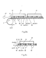
- the conveyor belt 2 (3) is removed in a rollable manner via a support over the accumulation rollers 23 or the support rollers 22, 22 ⁇ and carries 26 conveyor units 15 as a continuous conveyor on its underside.
- it can be the corridor over which the conveyor belt 2, 3 runs, in the case of removal via the support rollers 22 ⁇ , 23 ⁇ , U-rails can be embedded in the corridor, via which the conveyor belts 2, 3 are returned to the leading strand 9.
- the conveyor units l5 are initially carried by the accumulation rollers 23, while the support rollers 22, 22 ⁇ are on rails Support 28, 28 ⁇ , which are arranged parallel to the conveyor belt 2, 3 but at a certain height above it. Due to the rotational mobility of the roller holder 2l with its side walls 24, 24 ⁇ around the bolts l9, the conveyor units l5 are transported at a height above the conveyor belt 2, 3 which essentially corresponds to the height of the rollers in the further conveyor 27. In the area of the transfer between the conveyor belt and the further conveyor 27, the running rails 28, 28 ⁇ are tapered 29 or inclined.
- FIG. 2c A still further embodiment of the subject matter of the invention is shown in FIG. 2c.
- the conveyor belt 2, 3 runs over support rollers 30 in the direction of the arrow and carries the support rollers 22, 22 ⁇ and the accumulation rollers 23, which are guided via axle holders in roller holders 2l, and the accumulation rollers 23 50 shown connected.
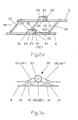
- 2d shows a connection according to the invention of two conveyor belts 2, 3 by means of rods 32, which simultaneously connect the axle holder 16 with the side walls 24, 24 24 of the two roll holders 2l as a replacement for the bolts.
- the support rollers 22, 22 ⁇ are arranged outside the side walls 24, 24 ⁇
- the accumulation rollers 23 are arranged inside the side walls 24, 24 ⁇ and the support rollers and accumulation rollers are connected via a shaft 25. Due to the large number of rods 32, which connect each pair of axle holders l6 and each pair of roller holders including side walls, a practically rigid coupling between conveyor belt 2 and conveyor belt 3 is produced, so that no complex straight and synchronous guides for the two conveyor belts have to be used .
- the roller holder 35 shown in FIG. 3a on a conveyor belt 2 is between two by means of two bolts l9 Axle holders l6 connected via its side walls 24, 24, on the one hand and via side wall extensions 36, 36 ⁇ on the other hand to the other axle holders l6.
- the side walls 24, 24 ⁇ and the side wall extensions 36, 36 ⁇ are made in one piece from elastic material, so that when the conveyor belt 2 is deflected by drive units 4 or deflection units 5, the lengthening of the conveyor belt pieces that occurs between the two axle holders due to the elastic deformation of the side walls and the side wall extensions can be recorded without the accumulation roller 23 or the support rollers 22, 22 'on the surface of the conveyor belt 2 grind.
- the rollers run free by an obtuse-angled arrangement of the side wall and the side wall extension to one another.
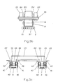
- FIG. 3b shows a conveyor belt 2 which is reinforced with steel cables 37 and on which the axle holder 16 is enclosed by the side walls 24, 24 'of the roller holder 2l.
- Guide blocks 39 are also provided on the roller holder 2l and, in the case of the exemplary embodiment according to FIG. 3b, simultaneously take over the guidance of a narrow conveyor belt 2 in the region of a rail guide for the idler rollers.
- the conveyor belts 2, 3 shown in Fig. 3c show a phase of transport in which the support rollers 22, 22 ⁇ run on rails 40, 40 ⁇ and thus take up the load of the conveyor unit, which is carried by the accumulation roller 23, so that the conveyor belts 2, 3 only have to apply the elastic train.
- individual guide blocks 4l, 4l ⁇ are provided, which are centered on side parts 42, 42 ⁇ of the rails 40, 40 ⁇ .
- the conveyor belts 2, 3 with their structures are surmounted by side parts 42, 42 ⁇ . With this, the conveyor belts 2, 3 run even in a channel that is lower than the normal floor area. On the one hand, protection of the conveyor belts 2, 3 is achieved and, on the other hand, U-shaped pallets 43, which stand with their short legs 44, 45 on the storage rollers, can be transported close to the hallway without the risk of a collision Cause injuries to objects or people, since the conveyed goods stop immediately due to the accumulation rollers.
- This embodiment of the subject matter of the invention also achieves the object on which the invention is based.
Landscapes
- Engineering & Computer Science (AREA)
- Mechanical Engineering (AREA)
- Structure Of Belt Conveyors (AREA)
Priority Applications (4)
| Application Number | Priority Date | Filing Date | Title |
|---|---|---|---|
| ES87101561T ES2017648B3 (es) | 1987-02-05 | 1987-02-05 | Procedimiento para el transporte y acoplamiento de palets, asi como el carril de rodillos para transporte y acoplamiento. |
| EP87101561A EP0277258B1 (fr) | 1987-02-05 | 1987-02-05 | Dispositif pour transporter et accumuler des palettes |
| DE8787101561T DE3764634D1 (de) | 1987-02-05 | 1987-02-05 | Vorrichtung zum transport und zum aufstauen von paletten. |
| US07/114,208 US4852718A (en) | 1987-02-05 | 1987-10-28 | Conveyor system |
Applications Claiming Priority (1)
| Application Number | Priority Date | Filing Date | Title |
|---|---|---|---|
| EP87101561A EP0277258B1 (fr) | 1987-02-05 | 1987-02-05 | Dispositif pour transporter et accumuler des palettes |
Publications (2)
| Publication Number | Publication Date |
|---|---|
| EP0277258A1 true EP0277258A1 (fr) | 1988-08-10 |
| EP0277258B1 EP0277258B1 (fr) | 1990-08-29 |
Family
ID=8196721
Family Applications (1)
| Application Number | Title | Priority Date | Filing Date |
|---|---|---|---|
| EP87101561A Expired - Lifetime EP0277258B1 (fr) | 1987-02-05 | 1987-02-05 | Dispositif pour transporter et accumuler des palettes |
Country Status (4)
| Country | Link |
|---|---|
| US (1) | US4852718A (fr) |
| EP (1) | EP0277258B1 (fr) |
| DE (1) | DE3764634D1 (fr) |
| ES (1) | ES2017648B3 (fr) |
Cited By (9)
| Publication number | Priority date | Publication date | Assignee | Title |
|---|---|---|---|---|
| DE3934233A1 (de) * | 1989-04-06 | 1990-10-11 | Duerr Gmbh & Co | Gurtfoerderer |
| DE9106634U1 (de) * | 1991-05-31 | 1991-10-17 | Fredenhagen Kg, 6050 Offenbach | Staufördergurt |
| EP0473953A1 (fr) * | 1990-09-05 | 1992-03-11 | Dürr GmbH | Transporteur de courroie |
| EP0523444A1 (fr) * | 1991-07-17 | 1993-01-20 | Continental Aktiengesellschaft | Courroie de transport avec des éléments d'accouplement |
| EP0558820A1 (fr) * | 1992-03-05 | 1993-09-08 | Stotz, Krämer GmbH Materialflussysteme und Automation | Convoyeur à bande à rouleaux d'accumulation |
| DE4219100A1 (de) * | 1992-06-11 | 1993-12-16 | Thyssen Aufzuege Gmbh | Staurollen-Gurtförderer |
| BE1008352A3 (fr) * | 1991-05-24 | 1996-04-02 | Mannesmann Ag | Transporteur a accumulation. |
| DE10355942A1 (de) * | 2003-11-29 | 2005-06-30 | Frank Schmid GmbH Förder- und Systemtechnik | Rollenstuhl für einen Gurtförderer |
| CN116161373A (zh) * | 2022-12-30 | 2023-05-26 | 江苏奔牛港务集团有限公司 | 袋装货物自动装卸设备及其控制方法 |
Families Citing this family (10)
| Publication number | Priority date | Publication date | Assignee | Title |
|---|---|---|---|---|
| DE4108613C2 (de) * | 1990-03-22 | 1995-05-24 | Eisenmann Foerdertech | Staugurtförderer |
| US5454687A (en) * | 1990-09-06 | 1995-10-03 | Johnson; Peter E. | High speed sorter/stacker |
| EP0800902B1 (fr) * | 1996-04-11 | 2002-03-06 | Dieffenbacher Schenck Panel GmbH | Procédé pour fabriquer en continu d'un mât pour panneaux en bois ou en matériau similaire |
| DE19615792C1 (de) * | 1996-04-20 | 1997-06-05 | Man Takraf Foerdertechnik Gmbh | Mitnehmerklappen für einen Senkrechtförderer für Schüttgut |
| US6168011B1 (en) | 1998-01-30 | 2001-01-02 | Sws Scharf-Westfalia Industrial Systems Gmbh | Accumulation conveyor system |
| US6102194A (en) * | 1999-02-16 | 2000-08-15 | Belcan Corporation | Pallet type transfer device |
| US6161685A (en) * | 1999-03-26 | 2000-12-19 | Rexnord Corporation | Thermoplastic chain link for a modular conveyor chain |
| IT249695Y1 (it) * | 2000-01-13 | 2003-05-28 | Fata Automation | Impianto di trasporto con trasportatore dotato di rulli folli di appoggio di elementi di trasporto |
| DE102004014745B4 (de) * | 2004-03-22 | 2009-01-02 | Telair International Gmbh | Frachtdeck |
| DE102011010544A1 (de) * | 2011-02-07 | 2012-08-09 | Eisenmann Ag | Tragbahnförderer und Förderanlage mit einem solchen |
Citations (2)
| Publication number | Priority date | Publication date | Assignee | Title |
|---|---|---|---|---|
| US3197020A (en) * | 1962-04-16 | 1965-07-27 | Ajem Lab Inc | Conveyor chain link |
| DE2210341A1 (de) * | 1971-03-06 | 1972-09-14 | Gianetti Spa | Rollenkette |
Family Cites Families (7)
| Publication number | Priority date | Publication date | Assignee | Title |
|---|---|---|---|---|
| US1768482A (en) * | 1930-06-24 | Conveyer mechanism | ||
| US722689A (en) * | 1902-01-02 | 1903-03-17 | H R Sanborn | Sheet-glass carrier for leers. |
| US1197145A (en) * | 1914-01-05 | 1916-09-05 | Samuel Olson | Package-conveyer. |
| US2687796A (en) * | 1946-02-25 | 1954-08-31 | Fmc Corp | Conveyer chain for can feeding mechanisms |
| US3174616A (en) * | 1962-10-15 | 1965-03-23 | Rex Chainbelt Inc | Conveyor chain and attachment |
| NL6705459A (fr) * | 1967-04-18 | 1968-10-21 | ||
| DE7728979U1 (de) * | 1977-09-19 | 1979-03-15 | Liebherr-Verzahntechnik Gmbh, 8960 Kempten | Vorrichtung zum foerdern schwerer gegenstaende oder paletten |
-
1987
- 1987-02-05 ES ES87101561T patent/ES2017648B3/es not_active Expired - Lifetime
- 1987-02-05 EP EP87101561A patent/EP0277258B1/fr not_active Expired - Lifetime
- 1987-02-05 DE DE8787101561T patent/DE3764634D1/de not_active Expired - Lifetime
- 1987-10-28 US US07/114,208 patent/US4852718A/en not_active Expired - Fee Related
Patent Citations (2)
| Publication number | Priority date | Publication date | Assignee | Title |
|---|---|---|---|---|
| US3197020A (en) * | 1962-04-16 | 1965-07-27 | Ajem Lab Inc | Conveyor chain link |
| DE2210341A1 (de) * | 1971-03-06 | 1972-09-14 | Gianetti Spa | Rollenkette |
Cited By (12)
| Publication number | Priority date | Publication date | Assignee | Title |
|---|---|---|---|---|
| DE3934233A1 (de) * | 1989-04-06 | 1990-10-11 | Duerr Gmbh & Co | Gurtfoerderer |
| EP0391247A3 (fr) * | 1989-04-06 | 1991-04-03 | Dürr GmbH | Convoyeur à bande portant des rouleaux d'accumulation |
| EP0473953A1 (fr) * | 1990-09-05 | 1992-03-11 | Dürr GmbH | Transporteur de courroie |
| DE4028130A1 (de) * | 1990-09-05 | 1992-03-12 | Duerr Gmbh & Co | Gurtfoerderer |
| BE1008352A3 (fr) * | 1991-05-24 | 1996-04-02 | Mannesmann Ag | Transporteur a accumulation. |
| DE9106634U1 (de) * | 1991-05-31 | 1991-10-17 | Fredenhagen Kg, 6050 Offenbach | Staufördergurt |
| EP0523444A1 (fr) * | 1991-07-17 | 1993-01-20 | Continental Aktiengesellschaft | Courroie de transport avec des éléments d'accouplement |
| EP0558820A1 (fr) * | 1992-03-05 | 1993-09-08 | Stotz, Krämer GmbH Materialflussysteme und Automation | Convoyeur à bande à rouleaux d'accumulation |
| DE4219100A1 (de) * | 1992-06-11 | 1993-12-16 | Thyssen Aufzuege Gmbh | Staurollen-Gurtförderer |
| DE10355942A1 (de) * | 2003-11-29 | 2005-06-30 | Frank Schmid GmbH Förder- und Systemtechnik | Rollenstuhl für einen Gurtförderer |
| CN116161373A (zh) * | 2022-12-30 | 2023-05-26 | 江苏奔牛港务集团有限公司 | 袋装货物自动装卸设备及其控制方法 |
| CN116161373B (zh) * | 2022-12-30 | 2023-06-23 | 江苏奔牛港务集团有限公司 | 袋装货物自动装卸设备及其控制方法 |
Also Published As
| Publication number | Publication date |
|---|---|
| DE3764634D1 (de) | 1990-10-04 |
| ES2017648B3 (es) | 1991-03-01 |
| EP0277258B1 (fr) | 1990-08-29 |
| US4852718A (en) | 1989-08-01 |
Similar Documents
| Publication | Publication Date | Title |
|---|---|---|
| EP0277258B1 (fr) | Dispositif pour transporter et accumuler des palettes | |
| EP2714496B1 (fr) | Dispositif de transport d'objets et installation de traitement de surface d'objets | |
| DE3528559A1 (de) | Sortieranlage | |
| EP1477437A2 (fr) | Système modulaire pour un convoyeur pour transporter des porte-pièces longitudinalement ou transversalement | |
| DE2838974C2 (de) | Rollenförderbahn mit nach oben offenem U-förmigen Trägern | |
| EP3529180B1 (fr) | Système de transport | |
| EP1897824B1 (fr) | Transporteur d'articles, en particulier pour bagages d'avions | |
| EP0541850B1 (fr) | Transporteur à palettes curviligne | |
| DE3317403C1 (de) | Stau-Haengefoerderer mit einer in der Horizontalebene umlaufenden,endlosen Trag- und Fuehrungsschiene | |
| DE10340868B4 (de) | Fördersystem, insbesondere eine Flughafengepäckförderanlage, für zum Transport von Stückgut dienenden Behältern | |
| DE3790593C2 (fr) | ||
| EP0750577B1 (fr) | Convoyeur aerien a simple voie ou a double voie | |
| EP2484607B1 (fr) | Dispositif de transport et installation de transport équipée de ce dispositif | |
| EP2610099B1 (fr) | Dispositif de transport pour marchandises légères à transporter, notamment pièces de véhicule | |
| EP0180177B1 (fr) | Dispositif pour le transport des marchandises, notamment pour le chargement de la surface portante d'un véhicule ou d'un conteneur | |
| DE10328555A1 (de) | Vorrichtung zum Ausschleusen von Lastträgern | |
| EP3169571A1 (fr) | Véhicule d'entraînement destiné à un dispositif de transport et système de transport | |
| DE10340867B4 (de) | Fördersystem, insbesondere eine Flughafen-Gepäckförderanlage | |
| DE3003180C2 (de) | Tragkettenförderer | |
| EP1619146A1 (fr) | Dispositif pour distribuer des porte-charges pour marchandises | |
| DE9312243U1 (de) | Fördereinrichtung | |
| EP1057758A1 (fr) | Convoyeur vertical selon le principe paternoster | |
| DE3929301A1 (de) | Schienenhaengebahn, insbesondere fuer den innerbetrieblichen materialtransport | |
| DE4323127A1 (de) | Kurvenbandförderer mit gurtbandrollenfreiem Traggerüst | |
| EP0088042B1 (fr) | Convoyeur-accumulateur réversible à chaînes pour marchandises allongées |
Legal Events
| Date | Code | Title | Description |
|---|---|---|---|
| PUAI | Public reference made under article 153(3) epc to a published international application that has entered the european phase |
Free format text: ORIGINAL CODE: 0009012 |
|
| 17P | Request for examination filed |
Effective date: 19871125 |
|
| AK | Designated contracting states |
Kind code of ref document: A1 Designated state(s): AT BE CH DE ES FR GB GR IT LI LU NL SE |
|
| RBV | Designated contracting states (corrected) |
Designated state(s): BE DE ES FR GB IT SE |
|
| 17Q | First examination report despatched |
Effective date: 19881031 |
|
| ITF | It: translation for a ep patent filed | ||
| GRAA | (expected) grant |
Free format text: ORIGINAL CODE: 0009210 |
|
| AK | Designated contracting states |
Kind code of ref document: B1 Designated state(s): BE DE ES FR GB IT SE |
|
| REF | Corresponds to: |
Ref document number: 3764634 Country of ref document: DE Date of ref document: 19901004 |
|
| GBT | Gb: translation of ep patent filed (gb section 77(6)(a)/1977) | ||
| ET | Fr: translation filed | ||
| PLBE | No opposition filed within time limit |
Free format text: ORIGINAL CODE: 0009261 |
|
| STAA | Information on the status of an ep patent application or granted ep patent |
Free format text: STATUS: NO OPPOSITION FILED WITHIN TIME LIMIT |
|
| 26N | No opposition filed | ||
| ITTA | It: last paid annual fee | ||
| EAL | Se: european patent in force in sweden |
Ref document number: 87101561.6 |
|
| PGFP | Annual fee paid to national office [announced via postgrant information from national office to epo] |
Ref country code: SE Payment date: 19960117 Year of fee payment: 10 |
|
| PGFP | Annual fee paid to national office [announced via postgrant information from national office to epo] |
Ref country code: GB Payment date: 19960119 Year of fee payment: 10 |
|
| PGFP | Annual fee paid to national office [announced via postgrant information from national office to epo] |
Ref country code: FR Payment date: 19960201 Year of fee payment: 10 |
|
| PGFP | Annual fee paid to national office [announced via postgrant information from national office to epo] |
Ref country code: ES Payment date: 19960213 Year of fee payment: 10 |
|
| PG25 | Lapsed in a contracting state [announced via postgrant information from national office to epo] |
Ref country code: GB Effective date: 19970205 |
|
| PG25 | Lapsed in a contracting state [announced via postgrant information from national office to epo] |
Ref country code: SE Effective date: 19970206 Ref country code: ES Free format text: LAPSE BECAUSE OF NON-PAYMENT OF DUE FEES Effective date: 19970206 |
|
| GBPC | Gb: european patent ceased through non-payment of renewal fee |
Effective date: 19970205 |
|
| PG25 | Lapsed in a contracting state [announced via postgrant information from national office to epo] |
Ref country code: FR Effective date: 19971030 |
|
| EUG | Se: european patent has lapsed |
Ref document number: 87101561.6 |
|
| REG | Reference to a national code |
Ref country code: FR Ref legal event code: ST |
|
| REG | Reference to a national code |
Ref country code: ES Ref legal event code: FD2A Effective date: 19990301 |
|
| PG25 | Lapsed in a contracting state [announced via postgrant information from national office to epo] |
Ref country code: IT Free format text: LAPSE BECAUSE OF NON-PAYMENT OF DUE FEES;WARNING: LAPSES OF ITALIAN PATENTS WITH EFFECTIVE DATE BEFORE 2007 MAY HAVE OCCURRED AT ANY TIME BEFORE 2007. THE CORRECT EFFECTIVE DATE MAY BE DIFFERENT FROM THE ONE RECORDED. Effective date: 20050205 |
|
| PGFP | Annual fee paid to national office [announced via postgrant information from national office to epo] |
Ref country code: BE Payment date: 20060203 Year of fee payment: 20 |
|
| PGFP | Annual fee paid to national office [announced via postgrant information from national office to epo] |
Ref country code: DE Payment date: 20060302 Year of fee payment: 20 |
|
| BE20 | Be: patent expired |
Owner name: *SCHENCK HANDLING SYSTEMS G.M.B.H. Effective date: 20070205 |