EP0277565A1 - Vorrichtung zur Bildstabilisierung für eine bewegliche Fernsehkamera - Google Patents
Vorrichtung zur Bildstabilisierung für eine bewegliche Fernsehkamera Download PDFInfo
- Publication number
- EP0277565A1 EP0277565A1 EP88100932A EP88100932A EP0277565A1 EP 0277565 A1 EP0277565 A1 EP 0277565A1 EP 88100932 A EP88100932 A EP 88100932A EP 88100932 A EP88100932 A EP 88100932A EP 0277565 A1 EP0277565 A1 EP 0277565A1
- Authority
- EP
- European Patent Office
- Prior art keywords
- camera
- horizontal
- angular
- portable video
- vertical
- Prior art date
- Legal status (The legal status is an assumption and is not a legal conclusion. Google has not performed a legal analysis and makes no representation as to the accuracy of the status listed.)
- Granted
Links
Images

Classifications
-
- H—ELECTRICITY
- H04—ELECTRIC COMMUNICATION TECHNIQUE
- H04N—PICTORIAL COMMUNICATION, e.g. TELEVISION
- H04N23/00—Cameras or camera modules comprising electronic image sensors; Control thereof
- H04N23/40—Circuit details for pick-up tubes
-
- H—ELECTRICITY
- H04—ELECTRIC COMMUNICATION TECHNIQUE
- H04N—PICTORIAL COMMUNICATION, e.g. TELEVISION
- H04N23/00—Cameras or camera modules comprising electronic image sensors; Control thereof
- H04N23/60—Control of cameras or camera modules
- H04N23/68—Control of cameras or camera modules for stable pick-up of the scene, e.g. compensating for camera body vibrations
-
- H—ELECTRICITY
- H04—ELECTRIC COMMUNICATION TECHNIQUE
- H04N—PICTORIAL COMMUNICATION, e.g. TELEVISION
- H04N23/00—Cameras or camera modules comprising electronic image sensors; Control thereof
- H04N23/60—Control of cameras or camera modules
- H04N23/68—Control of cameras or camera modules for stable pick-up of the scene, e.g. compensating for camera body vibrations
- H04N23/681—Motion detection
- H04N23/6812—Motion detection based on additional sensors, e.g. acceleration sensors
-
- H—ELECTRICITY
- H04—ELECTRIC COMMUNICATION TECHNIQUE
- H04N—PICTORIAL COMMUNICATION, e.g. TELEVISION
- H04N23/00—Cameras or camera modules comprising electronic image sensors; Control thereof
- H04N23/60—Control of cameras or camera modules
- H04N23/68—Control of cameras or camera modules for stable pick-up of the scene, e.g. compensating for camera body vibrations
- H04N23/682—Vibration or motion blur correction
Definitions
- the invention overcomes this problem by creating an image stabilizer for a portable video camera such that angular variations in the axis of the camera do not affect the output signal of the camera; that is, they definitively do not affect the position of the image with respect to the screen of the receiver.
- the converted signals can also take into account rotational movements about a horizontal axis and a vertical axis perpendicular to the axis of the objective, or lens.
- rotational movements about a horizontal axis and a vertical axis perpendicular to the axis of the objective, or lens.
- the invention relates to an image stabilizing apparatus for a portable video camera.
- Fig. 1 schematically shows a portable video camera and its main components, for the sake of better comprehension of the invention.
- the video camera includes an objective or lens 1, a target plate 2, an electron gun 3 and horizontal deflection coils 4 for scanning in the x direction and vertical deflection coils 5 for scanning in the y direction, although these coils may also be deflection plates.
- a subject 6 outside the camera forms an optical image 7 on the target plate 2 of a video camera, and this optical image is scanned by the cathode reading system of the camera with the aid of an electron beam emitted by the electron gun 3, which is deflected horizontally and vertically by the deflection coils 4 and 5 having vertical and horizontal fields, respectively.
- Fig. 2 in broken lines, shows the target plate 2 that has undergone a rotation about the optical axis OZ of the camera. It should be noted here that to obtain compensation for the displacements of the position of the image on the target plate, i.e., its stabilization, it is necessary that the target area should be greater than the area of the optical image projected on it by means of the objective or lens 1.
- the position of the target plate 2 of the camera may be defined in Cartesian coordinates, using a system of axes, x, y and z.
- the camera has undergone an angular variation about its optical axis OZ.
- a point in the optical image 7 on the plate 2 is defined at time 0 by its coordinates x0, y0, z. When this point has rotated by the angle ⁇ about the axis OZ, it is then defined by x t , y t , z (z is unchanged).
- Ix and Iy represent the currents that allow the vertical field and horizontal field of the deflection coils 4 and 5 to be created; in the absence of angular displacements of the camera, Ix, Iy are thus x and y scanning deflection currents for a camera lacking the image stabilization apparatus according to the invention.
- the signals Ix and Iy are generated by the camera, and the signals sin ⁇ and cos ⁇ can be generated by a sine and cosine converter associated with a rate gyroscope integrally connected with the camera and placed in such a manner that it provides a measure of the angular velocity of the camera about the axis of its objective.
- the entire apparatus thus functions as a vibration or oscillation damper for an elastically suspended camera.
- a rate gyroscope 10 has been shown, which is integrally connected to the camera of Fig. 1 and is located in such a manner that it provides a measure of the angular velocity of the camera about the axis OZ of its objective.
- the rate gyroscope 10 is connected at the output to an integrator 11 provided with a slow return to zero, so as to convert the angular velocity into an angle for rapid movements.
- This integrator is connected to a converter 12 of sine and cosine functions, which in turn is connected to a linear function converter circuit 13.
- the converter 12 thus furnishes two values, sin ⁇ and cos ⁇ , which are proportional to the sine and cosine of the angles of inclination of the camera with respect to its prior position, for rapid angular variations, and furnishes an increasingly reduced fraction of these functions when the angular velocity decreases.
- the sine and cosine converters mentioned above can be replaced by con verters operating upon the angle measured by the gyroscopic device to obtain polynomials or power series (Taylor) thereof respectively corresponding to these functions, which may use, in a first approximation, the first-order (linear) member only. If more precision is desired, higher-order polynomials may be used.
- the linear function circuit 13 is connected to the output of the circuit of the camera that furnishes the signals Ix and Iy, this circuit being shown at 14.
- the linear function circuit 13 comprises a multiplier and adder circuit suitable for performing multiplications and additions of signals, so that the above-mentioned converted signals I1x and I1y can be obtained. Multiplications and additions in this manner of signals generated on the one hand by the camera, relating to Ix and Iy, and on the other hand by the rate gyroscope, the integrator and the converter relating to ⁇ , are very easily performed in real time by analog or numerical circuits of a known type. It has been assumed above that the camera is angularly displaced about the optical axis OZ of its objective.
- the camera is displaced about an axis perpendicular to the optical axis of the camera, for example about the axis x of Fig. 2, which is in the horizontal plane.
- Fig. 4 shows the entire stabilization apparatus for arbitrary angular variations of the camera making use of the aforementioned provisions.
- any angular variation of the camera is defined in polar coordinates by the angles ⁇ , ⁇ and ⁇ above, so that the apparatus thus includes three rate gyroscopes 10a, 10b, 10c similar to the rate gyroscope 10 of Fig. 2, which are provided in order to furnish information corresponding to the angular variations ⁇ , ⁇ and ⁇ , respectively.
- the zoom lens which is controlled by rotation about the optical axis, is mechanically coupled (by gears or a belt and pulleys) to the wiper shaft of a potentiometer whose resistive path is connected between the terminals of a DC power supply, in order to deliver a voltage that is variable with the adjustment of the zoom lens. If the variations in the focusing of the zoom lens are nonlinear with the angle of rotation of its control device, the resistor of the potentiometer can be made to follow this nonlinear function.
- the various rate gyroscopes 10a, 10b, 10c are connected to integrators 11a, 11b, 11c, which in turn are connected to converters 12a, 12b, 12c.
- the converter 12a is a sine and cosine function converter, while the converters 12b and 12c respectively furnish a direct current K1 ⁇ and K2 ⁇ proportional to the angular variation detected by the corresponding gyroscope.
- a linear function circuit 13 ⁇ which receives the signals Ix and Iy from a circuit 14 ⁇ that is identical to the circuit 14 of Fig. 3, is connected to the output of the converters 12a, 12b and 12c.
- the dimensions of the image 7 furnished by the objective 1 and the target plate 2 of the camera must be such that the above values of the converted signals remain within the boundaries of the target plate.
- a switch located on the camera makes it possible to prevent functioning of the stabilization apparatus except when this is deemed useful.
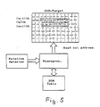
- the scanning is carried out in a matrix fashion, using a digital computer or microprocessors.
- the linear vertical and horizontal deflection of the scanned image field or of the starting point of the scan are relatively simple operations on the addresses of the read-out points.
- the rotation of the image about the optical axis of the camera is a more complex operation, because in order to obtain a line, several rows of the CCD elements have to be read consecutively.
- the angle of rotation ( ⁇ ) a certain number of successive elements of the nth row will have to be read, then the same number of elements of the (N + 1)th and so on, until the end of each line.
- the word "gyro tests” actually means a “rate gyroscope” or “rate gyro” which generates a signal proportional to the angular velocity of the rotation of the camera about its optical axis (a rate gyro being a gyroscope whose gimbal is restrained into a fixed position relatively to the object on which it is mounted by means of drawsprings and whose motion is damped).
- the signal is integrated in an integrator having a slow discharge rate (return to zero) to give an output signal proportional to the angle of rotation. Any other type of instrument (transducer) giving a voltage proportional to the angular displacement of the camera may be used.
- a gyroscope for model airplanes was successfully applied.
Landscapes
- Engineering & Computer Science (AREA)
- Multimedia (AREA)
- Signal Processing (AREA)
- Adjustment Of Camera Lenses (AREA)
- Studio Devices (AREA)
- Gyroscopes (AREA)
- Fittings On The Vehicle Exterior For Carrying Loads, And Devices For Holding Or Mounting Articles (AREA)
- Telescopes (AREA)
- Nitrogen Condensed Heterocyclic Rings (AREA)
- Heterocyclic Carbon Compounds Containing A Hetero Ring Having Oxygen Or Sulfur (AREA)
- Compositions Of Macromolecular Compounds (AREA)
Applications Claiming Priority (2)
| Application Number | Priority Date | Filing Date | Title |
|---|---|---|---|
| FR8700720A FR2610159B1 (fr) | 1987-01-22 | 1987-01-22 | Dispositif de stabilisation d'images pour camera video transportable |
| FR8700720 | 1987-01-22 |
Publications (2)
| Publication Number | Publication Date |
|---|---|
| EP0277565A1 true EP0277565A1 (de) | 1988-08-10 |
| EP0277565B1 EP0277565B1 (de) | 1996-04-03 |
Family
ID=9347157
Family Applications (2)
| Application Number | Title | Priority Date | Filing Date |
|---|---|---|---|
| EP88100932A Expired - Lifetime EP0277565B1 (de) | 1987-01-22 | 1988-01-22 | Vorrichtung zur Bildstabilisierung für eine bewegliche Fernsehkamera |
| EP88901249A Pending EP0343179A1 (de) | 1987-01-22 | 1988-01-22 | Vorrichtung zur bildstabilisierung für eine bewegliche fernsehkamera |
Family Applications After (1)
| Application Number | Title | Priority Date | Filing Date |
|---|---|---|---|
| EP88901249A Pending EP0343179A1 (de) | 1987-01-22 | 1988-01-22 | Vorrichtung zur bildstabilisierung für eine bewegliche fernsehkamera |
Country Status (10)
| Country | Link |
|---|---|
| US (1) | US5012347A (de) |
| EP (2) | EP0277565B1 (de) |
| JP (1) | JPH02502327A (de) |
| KR (1) | KR960008931B1 (de) |
| AT (1) | ATE136415T1 (de) |
| DE (1) | DE3855169T2 (de) |
| ES (1) | ES2087851T3 (de) |
| FR (1) | FR2610159B1 (de) |
| HK (1) | HK131597A (de) |
| WO (1) | WO1988005623A1 (de) |
Cited By (1)
| Publication number | Priority date | Publication date | Assignee | Title |
|---|---|---|---|---|
| EP0456414A3 (en) * | 1990-05-11 | 1992-05-20 | Matsushita Electric Industrial Co., Ltd | Slant correction for a video camera apparatus |
Families Citing this family (19)
| Publication number | Priority date | Publication date | Assignee | Title |
|---|---|---|---|---|
| JP2685249B2 (ja) * | 1988-10-27 | 1997-12-03 | キヤノン株式会社 | 撮影条件決定装置 |
| JP2775878B2 (ja) * | 1989-07-26 | 1998-07-16 | キヤノン株式会社 | 防振撮像装置 |
| JP2803072B2 (ja) * | 1990-10-18 | 1998-09-24 | 富士写真フイルム株式会社 | 手振れ補正装置 |
| JP3170716B2 (ja) * | 1991-06-21 | 2001-05-28 | 株式会社ニコン | 撮影装置の像ぶれ補正装置 |
| US5438361A (en) * | 1992-04-13 | 1995-08-01 | Hughes Aircraft Company | Electronic gimbal system for electronically aligning video frames from a video sensor subject to disturbances |
| JPH06205249A (ja) * | 1992-10-22 | 1994-07-22 | Konica Corp | ビデオカメラ |
| US5504523A (en) * | 1993-10-21 | 1996-04-02 | Loral Fairchild Corporation | Electronic image unsteadiness compensation |
| JPH086089A (ja) * | 1994-06-16 | 1996-01-12 | Nikon Corp | 振れ防止装置 |
| EP0698777B1 (de) * | 1994-07-22 | 2002-02-20 | Hughes Electronics Corporation | Satellitenkamera mit Bildebenenarray |
| US6723550B1 (en) | 1997-07-15 | 2004-04-20 | Genencor International, Inc. | Proteases from gram-positive organisms |
| US7742073B1 (en) | 2000-11-01 | 2010-06-22 | Koninklijke Philips Electronics N.V. | Method and apparatus for tracking an object of interest using a camera associated with a hand-held processing device |
| US20040100563A1 (en) | 2002-11-27 | 2004-05-27 | Sezai Sablak | Video tracking system and method |
| US7382400B2 (en) * | 2004-02-19 | 2008-06-03 | Robert Bosch Gmbh | Image stabilization system and method for a video camera |
| US7742077B2 (en) * | 2004-02-19 | 2010-06-22 | Robert Bosch Gmbh | Image stabilization system and method for a video camera |
| US8212872B2 (en) * | 2004-06-02 | 2012-07-03 | Robert Bosch Gmbh | Transformable privacy mask for video camera images |
| US9210312B2 (en) | 2004-06-02 | 2015-12-08 | Bosch Security Systems, Inc. | Virtual mask for use in autotracking video camera images |
| US20050270372A1 (en) * | 2004-06-02 | 2005-12-08 | Henninger Paul E Iii | On-screen display and privacy masking apparatus and method |
| JP4133990B2 (ja) * | 2004-10-01 | 2008-08-13 | 株式会社タムロン | アクチュエータ及びそれを備えたレンズユニット及びカメラ |
| US20060078162A1 (en) * | 2004-10-08 | 2006-04-13 | Dynapel, Systems, Inc. | System and method for stabilized single moving camera object tracking |
Citations (3)
| Publication number | Priority date | Publication date | Assignee | Title |
|---|---|---|---|---|
| US3619500A (en) * | 1969-06-04 | 1971-11-09 | Hughes Aircraft Co | Electronic image motion stabilization system |
| EP0149365A2 (de) * | 1983-12-29 | 1985-07-24 | Matsushita Electric Industrial Co., Ltd. | Kameraanordnung |
| EP0200442A2 (de) * | 1985-04-18 | 1986-11-05 | Matsushita Electric Industrial Co., Ltd. | Kameraanordnung |
Family Cites Families (4)
| Publication number | Priority date | Publication date | Assignee | Title |
|---|---|---|---|---|
| US3577205A (en) * | 1965-11-19 | 1971-05-04 | Itek Corp | Automatic image motion stabilization system |
| JPS5955681A (ja) * | 1982-09-24 | 1984-03-30 | Mitsubishi Electric Corp | 撮像装置 |
| JPS5955680A (ja) * | 1982-09-24 | 1984-03-30 | Mitsubishi Electric Corp | 撮像装置 |
| JPS61191171A (ja) * | 1985-02-19 | 1986-08-25 | Matsushita Electric Ind Co Ltd | 撮影装置 |
-
1987
- 1987-01-22 FR FR8700720A patent/FR2610159B1/fr not_active Expired
-
1988
- 1988-01-22 EP EP88100932A patent/EP0277565B1/de not_active Expired - Lifetime
- 1988-01-22 DE DE3855169T patent/DE3855169T2/de not_active Expired - Fee Related
- 1988-01-22 AT AT88100932T patent/ATE136415T1/de not_active IP Right Cessation
- 1988-01-22 WO PCT/EP1988/000045 patent/WO1988005623A1/en not_active Ceased
- 1988-01-22 JP JP63501457A patent/JPH02502327A/ja active Pending
- 1988-01-22 EP EP88901249A patent/EP0343179A1/de active Pending
- 1988-01-22 ES ES88100932T patent/ES2087851T3/es not_active Expired - Lifetime
- 1988-01-22 US US07/399,524 patent/US5012347A/en not_active Expired - Fee Related
- 1988-01-22 KR KR1019880701147A patent/KR960008931B1/ko not_active Expired - Fee Related
-
1997
- 1997-06-26 HK HK131597A patent/HK131597A/en not_active IP Right Cessation
Patent Citations (3)
| Publication number | Priority date | Publication date | Assignee | Title |
|---|---|---|---|---|
| US3619500A (en) * | 1969-06-04 | 1971-11-09 | Hughes Aircraft Co | Electronic image motion stabilization system |
| EP0149365A2 (de) * | 1983-12-29 | 1985-07-24 | Matsushita Electric Industrial Co., Ltd. | Kameraanordnung |
| EP0200442A2 (de) * | 1985-04-18 | 1986-11-05 | Matsushita Electric Industrial Co., Ltd. | Kameraanordnung |
Non-Patent Citations (2)
| Title |
|---|
| PATENT ABSTRACTS OF JAPAN, vol. 8, no. 149 (E-255)[1586], 12th July 1984; & JP-A-59 055 680 (MITSUBISHI DENKI K.K.) 30-03-1984 * |
| PATENT ABSTRACTS OF JAPAN, vol. 8, no. 149 (E-255)[1586], 12th July 1984; & JP-A-59 055 681 (MITSUBISHI DENKI K.K.) 30-03-1984 * |
Cited By (1)
| Publication number | Priority date | Publication date | Assignee | Title |
|---|---|---|---|---|
| EP0456414A3 (en) * | 1990-05-11 | 1992-05-20 | Matsushita Electric Industrial Co., Ltd | Slant correction for a video camera apparatus |
Also Published As
| Publication number | Publication date |
|---|---|
| US5012347A (en) | 1991-04-30 |
| KR890700987A (ko) | 1989-04-28 |
| WO1988005623A1 (en) | 1988-07-28 |
| ES2087851T3 (es) | 1996-08-01 |
| DE3855169T2 (de) | 1996-10-02 |
| ATE136415T1 (de) | 1996-04-15 |
| DE3855169D1 (de) | 1996-05-15 |
| EP0343179A1 (de) | 1989-11-29 |
| EP0277565B1 (de) | 1996-04-03 |
| FR2610159B1 (fr) | 1989-04-07 |
| HK131597A (en) | 1997-09-26 |
| JPH02502327A (ja) | 1990-07-26 |
| FR2610159A1 (fr) | 1988-07-29 |
| KR960008931B1 (ko) | 1996-07-09 |
Similar Documents
| Publication | Publication Date | Title |
|---|---|---|
| US5012347A (en) | Image stabilizing apparatus for a portable video camera | |
| US5450126A (en) | Image blur correcting apparatus | |
| US4637571A (en) | Electronic image stabilization | |
| US5619030A (en) | Control apparatus for image blur prevention employing an angular velocity and an image field sensor | |
| US5243462A (en) | Image stabilizing apparatus | |
| CA2093160C (en) | Electronic gimbal system | |
| EP0388936A2 (de) | Bildaufnahmevorrichtung | |
| JP6535524B2 (ja) | 撮像装置 | |
| US5285313A (en) | Image stabilizing apparatus | |
| JPH06165020A (ja) | 振れ補正装置 | |
| US6067419A (en) | Image blur prevention apparatus | |
| US5768634A (en) | Hand deviation correction apparatus | |
| JP3548328B2 (ja) | 撮像装置 | |
| EP0488721A1 (de) | Bewegungsdetektion | |
| JP2902726B2 (ja) | 像ぶれ補正装置 | |
| JP2641599B2 (ja) | 動きベクトル検出装置 | |
| Tchernykh et al. | Optical-correlator-based system for the real-time analysis of image motion in the focal plane of an Earth observation camera | |
| JPH06296252A (ja) | ビデオカメラ装置 | |
| JP2002057932A (ja) | 撮像装置 | |
| EP0396981A1 (de) | Bildstabilisationsvorrichtung | |
| JPH075514A (ja) | 補正光学装置 | |
| GB2273223A (en) | Correcting image blur due to camera movement | |
| JPH04163533A (ja) | 手振れ補正装置 | |
| JPS6326082A (ja) | ビデオカメラのオ−トフオ−カス装置 | |
| JP3226586B2 (ja) | 画像振れ防止装置 |
Legal Events
| Date | Code | Title | Description |
|---|---|---|---|
| PUAI | Public reference made under article 153(3) epc to a published international application that has entered the european phase |
Free format text: ORIGINAL CODE: 0009012 |
|
| AK | Designated contracting states |
Kind code of ref document: A1 Designated state(s): ES GR |
|
| 17P | Request for examination filed |
Effective date: 19890117 |
|
| XX | Miscellaneous (additional remarks) |
Free format text: VERBUNDEN MIT 88901249.8/0343179 (EUROPAEISCHE ANMELDENUMMER/VEROEFFENTLICHUNGSNUMMER) DURCH ENTSCHEIDUNG VOM 14.03.91. |
|
| 17Q | First examination report despatched |
Effective date: 19910925 |
|
| GRAA | (expected) grant |
Free format text: ORIGINAL CODE: 0009210 |
|
| AK | Designated contracting states |
Kind code of ref document: B1 Designated state(s): AT BE CH DE ES FR GB GR IT LI LU NL SE |
|
| PG25 | Lapsed in a contracting state [announced via postgrant information from national office to epo] |
Ref country code: LI Effective date: 19960403 Ref country code: GR Free format text: LAPSE BECAUSE OF FAILURE TO SUBMIT A TRANSLATION OF THE DESCRIPTION OR TO PAY THE FEE WITHIN THE PRESCRIBED TIME-LIMIT Effective date: 19960403 Ref country code: CH Effective date: 19960403 Ref country code: BE Effective date: 19960403 |
|
| REF | Corresponds to: |
Ref document number: 136415 Country of ref document: AT Date of ref document: 19960415 Kind code of ref document: T |
|
| XX | Miscellaneous (additional remarks) |
Free format text: VERBUNDEN MIT 88901249.8/0343179 (EUROPAEISCHE ANMELDENUMMER/VEROEFFENTLICHUNGSNUMMER) DURCH ENTSCHEIDUNG VOM 14.03.91. |
|
| ITF | It: translation for a ep patent filed | ||
| REF | Corresponds to: |
Ref document number: 3855169 Country of ref document: DE Date of ref document: 19960515 |
|
| ET | Fr: translation filed | ||
| REG | Reference to a national code |
Ref country code: ES Ref legal event code: BA2A Ref document number: 2087851 Country of ref document: ES Kind code of ref document: T3 |
|
| REG | Reference to a national code |
Ref country code: ES Ref legal event code: FG2A Ref document number: 2087851 Country of ref document: ES Kind code of ref document: T3 |
|
| REG | Reference to a national code |
Ref country code: CH Ref legal event code: PL |
|
| PG25 | Lapsed in a contracting state [announced via postgrant information from national office to epo] |
Ref country code: AT Free format text: LAPSE BECAUSE OF NON-PAYMENT OF DUE FEES Effective date: 19970122 |
|
| PG25 | Lapsed in a contracting state [announced via postgrant information from national office to epo] |
Ref country code: LU Free format text: LAPSE BECAUSE OF NON-PAYMENT OF DUE FEES Effective date: 19970131 |
|
| PLBE | No opposition filed within time limit |
Free format text: ORIGINAL CODE: 0009261 |
|
| STAA | Information on the status of an ep patent application or granted ep patent |
Free format text: STATUS: NO OPPOSITION FILED WITHIN TIME LIMIT |
|
| 26N | No opposition filed | ||
| PGFP | Annual fee paid to national office [announced via postgrant information from national office to epo] |
Ref country code: GB Payment date: 19971219 Year of fee payment: 11 |
|
| PGFP | Annual fee paid to national office [announced via postgrant information from national office to epo] |
Ref country code: FR Payment date: 19971231 Year of fee payment: 11 |
|
| PGFP | Annual fee paid to national office [announced via postgrant information from national office to epo] |
Ref country code: NL Payment date: 19980121 Year of fee payment: 11 |
|
| PGFP | Annual fee paid to national office [announced via postgrant information from national office to epo] |
Ref country code: SE Payment date: 19980122 Year of fee payment: 11 |
|
| PGFP | Annual fee paid to national office [announced via postgrant information from national office to epo] |
Ref country code: DE Payment date: 19980123 Year of fee payment: 11 |
|
| PGFP | Annual fee paid to national office [announced via postgrant information from national office to epo] |
Ref country code: ES Payment date: 19980130 Year of fee payment: 11 |
|
| PG25 | Lapsed in a contracting state [announced via postgrant information from national office to epo] |
Ref country code: GB Free format text: LAPSE BECAUSE OF NON-PAYMENT OF DUE FEES Effective date: 19990122 |
|
| PG25 | Lapsed in a contracting state [announced via postgrant information from national office to epo] |
Ref country code: SE Free format text: LAPSE BECAUSE OF NON-PAYMENT OF DUE FEES Effective date: 19990123 Ref country code: ES Free format text: THE PATENT HAS BEEN ANNULLED BY A DECISION OF A NATIONAL AUTHORITY Effective date: 19990123 |
|
| PG25 | Lapsed in a contracting state [announced via postgrant information from national office to epo] |
Ref country code: NL Free format text: LAPSE BECAUSE OF NON-PAYMENT OF DUE FEES Effective date: 19990801 |
|
| GBPC | Gb: european patent ceased through non-payment of renewal fee |
Effective date: 19990122 |
|
| PG25 | Lapsed in a contracting state [announced via postgrant information from national office to epo] |
Ref country code: FR Free format text: LAPSE BECAUSE OF NON-PAYMENT OF DUE FEES Effective date: 19990930 |
|
| PG25 | Lapsed in a contracting state [announced via postgrant information from national office to epo] |
Ref country code: DE Free format text: LAPSE BECAUSE OF NON-PAYMENT OF DUE FEES Effective date: 19991103 |
|
| REG | Reference to a national code |
Ref country code: FR Ref legal event code: ST |
|
| REG | Reference to a national code |
Ref country code: ES Ref legal event code: FD2A Effective date: 20010604 |
|
| PG25 | Lapsed in a contracting state [announced via postgrant information from national office to epo] |
Ref country code: IT Free format text: LAPSE BECAUSE OF NON-PAYMENT OF DUE FEES;WARNING: LAPSES OF ITALIAN PATENTS WITH EFFECTIVE DATE BEFORE 2007 MAY HAVE OCCURRED AT ANY TIME BEFORE 2007. THE CORRECT EFFECTIVE DATE MAY BE DIFFERENT FROM THE ONE RECORDED. Effective date: 20050122 |