EP0277615B1 - Collecteur de particules fines pour des pompes à vide - Google Patents
Collecteur de particules fines pour des pompes à vide Download PDFInfo
- Publication number
- EP0277615B1 EP0277615B1 EP88101379A EP88101379A EP0277615B1 EP 0277615 B1 EP0277615 B1 EP 0277615B1 EP 88101379 A EP88101379 A EP 88101379A EP 88101379 A EP88101379 A EP 88101379A EP 0277615 B1 EP0277615 B1 EP 0277615B1
- Authority
- EP
- European Patent Office
- Prior art keywords
- fine particle
- temperature wall
- low temperature
- particle collector
- wall member
- Prior art date
- Legal status (The legal status is an assumption and is not a legal conclusion. Google has not performed a legal analysis and makes no representation as to the accuracy of the status listed.)
- Expired - Lifetime
Links
- 239000010419 fine particle Substances 0.000 title description 30
- 239000004020 conductor Substances 0.000 description 9
- 239000011882 ultra-fine particle Substances 0.000 description 9
- 239000002826 coolant Substances 0.000 description 6
- 238000010438 heat treatment Methods 0.000 description 5
- 238000001816 cooling Methods 0.000 description 4
- 239000004065 semiconductor Substances 0.000 description 4
- 238000004140 cleaning Methods 0.000 description 3
- 238000010276 construction Methods 0.000 description 3
- 239000002245 particle Substances 0.000 description 3
- 239000000428 dust Substances 0.000 description 2
- 238000012423 maintenance Methods 0.000 description 2
- 238000004519 manufacturing process Methods 0.000 description 2
- 238000001556 precipitation Methods 0.000 description 2
- 230000005653 Brownian motion process Effects 0.000 description 1
- 230000005679 Peltier effect Effects 0.000 description 1
- BLRPTPMANUNPDV-UHFFFAOYSA-N Silane Chemical compound [SiH4] BLRPTPMANUNPDV-UHFFFAOYSA-N 0.000 description 1
- 238000010521 absorption reaction Methods 0.000 description 1
- 230000002411 adverse Effects 0.000 description 1
- 238000005537 brownian motion Methods 0.000 description 1
- 230000001143 conditioned effect Effects 0.000 description 1
- 230000003750 conditioning effect Effects 0.000 description 1
- 230000007547 defect Effects 0.000 description 1
- 238000009792 diffusion process Methods 0.000 description 1
- 230000000694 effects Effects 0.000 description 1
- 239000012212 insulator Substances 0.000 description 1
- 238000012986 modification Methods 0.000 description 1
- 230000004048 modification Effects 0.000 description 1
- 238000005268 plasma chemical vapour deposition Methods 0.000 description 1
- 238000007789 sealing Methods 0.000 description 1
Images

Classifications
-
- F—MECHANICAL ENGINEERING; LIGHTING; HEATING; WEAPONS; BLASTING
- F04—POSITIVE - DISPLACEMENT MACHINES FOR LIQUIDS; PUMPS FOR LIQUIDS OR ELASTIC FLUIDS
- F04B—POSITIVE-DISPLACEMENT MACHINES FOR LIQUIDS; PUMPS
- F04B37/00—Pumps having pertinent characteristics not provided for in, or of interest apart from, groups F04B25/00 - F04B35/00
- F04B37/06—Pumps having pertinent characteristics not provided for in, or of interest apart from, groups F04B25/00 - F04B35/00 for evacuating by thermal means
-
- F—MECHANICAL ENGINEERING; LIGHTING; HEATING; WEAPONS; BLASTING
- F04—POSITIVE - DISPLACEMENT MACHINES FOR LIQUIDS; PUMPS FOR LIQUIDS OR ELASTIC FLUIDS
- F04B—POSITIVE-DISPLACEMENT MACHINES FOR LIQUIDS; PUMPS
- F04B39/00—Component parts, details, or accessories, of pumps or pumping systems specially adapted for elastic fluids, not otherwise provided for in, or of interest apart from, groups F04B25/00 - F04B37/00
- F04B39/16—Filtration; Moisture separation
Definitions
- the present invention relates to a fine particle collector arrangement for vacuum pumps, which is installed between a vacuum processing chamber and the vacuum pump for collecting fine particles, such as dusts or the like existing in the vacuum processing chamber before they are carried to the vacuum pumps.
- the vacuum chamber of a film forming apparatus in which dust in large quantity may be generated is, for example, evacuated by a vacuum pump
- a mesh member for adhering or collecting the dusts in a gas to be evacuated, the mesh member being interposed in an evacuating passage to protect the vacuum pump from the dusts.
- a drum rotating in oil is provided in the evacuating passage to adhere the dusts in the gas to be evacuated to the surface of the drum or small articles which are contained in the drum.
- produced ultrafine particles are deposited in a collecting chamber to be collected.
- the produced ultrafine particles are intaken together with the evacuated gas by the vacuum pump to cause defects to deteriorate the efficiency for collecting these particles.
- This known arrangement is such that the hot fins are welded to the relevant hot medium conduct and the cold fins are welded to the relevant cold medium conduct.
- the arrangement of hot and cold fins is housed within an air duct. This arrangement is such that neither the cold nor the hot fins can be removed from the air duct for cleaning thereof.
- an object of the present invention to solve the drawbacks of the above-mentioned conventional apparatuses and to provide a fine particle collector arrangement for vacuum pumps which can effectively collect fine particles such as dusts or the like in low pressure gas without raising the pressure difference between a vacuum chamber and an evacuating system.
- Another object of the invention is to provide a fine particle collector arrangement for vacuum pumps which makes it possible to use a vacuum pump obtaining relatively high vacuum with ready manufacture and provide easy maintenance.
- a further object of the invention is to provide a fine particle collector arrangement for vacuum pumps which may be utilized for collecting ultrafine particles produced in an ultrafine particle producing apparatus.
- a fine particle collector arrangement for vacuum pumps comprising a fine particle collecting chamber having an inlet conduit connected to a vacuum processing chamber in which a processing is performed and an outlet conduit connected to at least one vacuum pump, and at least one high temperature wall member and at least one low temperature wall member which are disposed oppositely to each other in said fine particle collecting chamber to define a flow passage having a temperature gradient from said high temperature wall member to said low temperature wall member.
- the fine particle collecting chamber includes a chamber body which has an inner surface on which said low temperature wall member is connected and a removable cover for the chamber body, on which said high temperature wall member is connected.
- said flow passage has larger cross section than that of said inlet conduit.
- said fine particle collecting chamber may be provided with a plurality of platelike high temperature wall members and a plurality of platelike low temperature wall members which are alternately interposed to form said passage in a zigzag shape.
- the wall members may be arranged so as to form parallel flow channels.
- the inlet conduit may be connected, for example, to the vacuum chamber of the film forming apparatus, and the outlet conduit may be connected to the vacuum pump for evacuating in low or middle vacuum.
- gas prevailing in the vacuum chamber is intaken through the passage in the collecting chamber to the vacuum pump, and fine particles such as dusts in the gas intaken by the vacuum pump move at a certain velocity by the thermophoretic force from the high temperature side to the low temperature side in the passage of the collecting chamber to be adhered to the low temperature wall members.
- the fine particles have the same moving velocity at lower temperature gradient, the smaller the pressure becomes, the fine particles in the gas can be sufficiently attracted to the low temperature wall members even when the space between the respective low temperature wall member and the respective high temperature wall member is increased to reduce the temperature gradient, i.e., when the cross section of the flow passage is increased.
- the flow passage in the collecting chamber is formed in a zigzag shape, a long passage for effectively removing the fine particles from the gas can be easily obtained in a small-sized collecting chamber. Since the cross section of the collecting passage is larger than that of the inlet conduit the pressure difference required to collect fine particles may be small, so that a vacuum pump of relatively high vacuum type there may be used, thereby rapidly reducing the pressure in the vacuum chamber.
- reference numeral 1 designates a fine particle collecting chamber which comprises a chamber body 1a and a cover 1b tightly fixed on the flange thereof via a sealing member 2.
- the chamber body 1a is provided with an inlet conduit 3 at one side wall thereof which is connected to a vacuum chamber 4 for a film forming apparatus (not shown) and an outlet conduit 5 at the other side wall which is connected to a vacuum pump 6 such as a mechanical booster pump.
- the inlet conduit 3 and the outlet conduit 5 are interconnected by a bypass conduit 7.
- the inlet conduit 3 is provided with a valve 8, the outlet conduit 5 with a valve 9, and the bypass conduit 7 with two valves 10 and 11.
- the chamber 1 there are disposed five platelike high temperature wall members 12 and five platelike low temperature wall members 13 which are alternately interposed to form a flow passage 14 in a zigzag shape.
- This zigzag passage 14 is so arranged that it has a larger cross section than the of the inlet conduit 3.
- Each of the high temperature wall members 12 is downwards fixed on the inner surface of the cover 1b.
- Each of the low temperature wall members 13 is upwards fixed on the inner surface of the chamber body 1a.
- the chamber body 1a is provided with a coolant channel 15 around the outer surface thereof for cooling the low temperature wall members 13.
- the coolant channel 15 comprises a coolant feeding-in conduit 16 and a coolant feeding-out conduit 17.
- the cover 1b is provided with a heater 18 therein for heating the high temperature wall members 12. This heater may be energized by a suitable power supply (not shown). It is appreciated that such cooling means and heating means may be arbitrarily provided, and if desired, the heater may be directly buried in the respective high temperature wall members 12.
- the high temperature wall members 12, for example, at 120°C and the low temperature wall members 13 at 20°C are alternately provided, a temperature gradient occurs perpendicularly across the passage 14 in the gas flowing therethrough, and the fine particles in the gas move from high temperature side to low temperature side in the zigzag passage 14 at a certain velocity by the thermophoretic force and is to be deposited on the low temperature wall members 13.
- each high temperature wall member 12 and the adjacent low temperature wall member 13 can be increased to a certain extent so as to collect the fine particles from the gas flowing at low pressure, and consequently it becomes possible to almost arbitrarily increase the cross section of the passage 14 as compared with that of the inlet conduit 3, considering that the chamber 1 may take a very large lateral width.
- the pressure difference required for feeding to the passage 14 can be substantially reduced, and not only low vacuum pump but also a vacuum pump having relatively high vacuum performance can be available. Further, since the performance of the used vacuum pump can be suffficiently utilized, the pressure of the vacuum chamber 4 can be evacuated to relatively higher vacuum.
- valves 8 and 9 in the inlet and outlet conduits 3 and 5 are closed, the valves 10 and 11 in the bypass conduit 7 are so opened to bypass the gas through the bypass conduit 7, and then it can be avoided that the fine particles collected in the chamber 1 are whirled up by the pressure variation occurred due to the energizing and deenergizing of the vacuum pump 2 and are fed out from the chamber 1.
- the fine particles deposited on the low temperature wall members 13 and the other portion in the chamber 1 can be easily removed by removing the upper cover 1b.
- the size of the collecting chamber 1 may be selected depending upon the gas flow rate to be passed.
- the collecting chamber 1 is formed at approx. 50 cm length L, 55 cm height and 50 cm lateral width, five high temperature wall members 12 of plate shape having each of height 50 cm and lateral width 49.5 cm are provided and heated to approx. 120°C, four low temperature wall members 13 of plate shape each having height 50 cm and lateral width 50 cm are provided and cooled to 20°C, and the space d between the adjacent high and low temperature wall members is set to 4 cm.
- the pressure in the collecting chamber 132 to 660 Pa (1 is 5 Torr
- the pressure difference between the inlet conduit 3 and the outlet conduit 5 becomes 1,32 Pa (10 ⁇ 2 Torr) or lower.
- the inlet conduit is connected to a vacuum chamber in which ultrafine particles are produced.
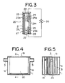
- Figs. 2 and 3 show a modified embodiment of the present invention, in which the components are the same as those in the first embodiment of Fig. 1 except that the construction of a high and low temperature wall members is different from that of the first embodiment.
- the reference numerals are used to designate the components corresponding to those in the first embodiment.
- each wall member 20 comprises an outer hollow wall 21 and two electronic cooling elements 22 utilizing Peltier effect which are contained in the outer hollow wall 21, and one is P-type semiconductor and the other N-type semiconductor.
- One ends of both semiconductors 22 are connected to each other by means of a common terminal conductor strip 23, and the other ends thereof are connected to separated terminal conductor strips 24 and 25, respectively.
- the separated terminal conductor stripes 24 and 25 are connected to a direct current souce 26. Further, between the outer hollow wall 21 and each of the common terminal conductor strip 23 and the separated terminal conductor strips 24 and 25, there are respectively interposed insulator members 27 and 28.
- the semiconductor elements 22 are supplied with DC current from the source 26, the surfaces 24a and 25a of the terminal conductor strips 24 and 25 are heated and the surface 23a of the terminal conductor strip 23 is cooled. Therefore, the terminal conductor strips 24 and 25 behave as a heating element and the common terminal conductor strip 23 behaves as a heat absorption element, and thus one side 21H of the outer hollow wall 21 constitutes high temperature wall surface and the other side 21L thereof low temperature wall surface.
- the both side walls 21H and 21L of the outer hollow wall 21 should be preferably thermally insulated in order to avoid any reduction of the temperature difference therebetween.
- Figs. 4 and 5 show a modification of the second embodiment of Figs. 2 and 3, in which the components are the same as those in the second embodiment except that the arrangement of the high and low temperature wall members is different from that of the second embodiment.
- the reference numerals are used to designate the components corresponding to those in the second embodiment.
- each of the wall members 30 has substantially the same construction as that of the wall member 20 shown in Fig. 3, but all of them are disposed on the cover 1b of the collecting chamber 1 so that a plurality of parallel flow channels 31 are formed.
- the construction of the device can be more simplified and also the cleaning thereof can be more easily performed.
- first embodiment of the present invention shown in Fig. 1, may be modified as shown in Figs. 4 and 5.
- each of the high temperature wall members is fixed on the inner surface of the cover 1b which is provided with the heater
- each of the low temperature wall members is fixed on the inner surface of the chamber body which is provided with a coolant channel, and a plurality of platelike high temperature wall members and a plurality of platelike low temperature wall menbers are alternately interposed to form said parallel flow channels.
- high temperature walls and low temperature walls are alternately provided in the collecting chamber to form gas flow passage(s) which is extended from the inlet conduit connected with the vacuum processing chamber to the outlet conduit connected with the vacuum pump, and the gas flow passage(s) has larger cross section than that of the inlet conduit. Therefore, fine particles in gas flowing from the inlet conduit may be deposited on the each low temperature wall member to be efficiently collected. Since no pressure difference is generated to collect the fine particles, the performance of the vacuum pump can not be deteriorated, thereby highly evacuating the vacuum processing chamber. Further, it is possible to collect the fine particles in a dry system without using oil, and thus the vacuum processing chamber is not contaminated.
- the present invention has also advantage that it is possible to simplify the manufacture and to perform readily the maintenance.
Landscapes
- Engineering & Computer Science (AREA)
- Mechanical Engineering (AREA)
- General Engineering & Computer Science (AREA)
- Compressors, Vaccum Pumps And Other Relevant Systems (AREA)
- Compressor (AREA)
Claims (8)
- Collecteur de particules fines pour pompes à vide comprenant au moins une paroi à haute température en forme de plaque (12 ; 20) et au moins une paroi à basse température en forme de plaque (13 ; 20), les parois à haute et basse température (12, 13) étant disposées en regard et de façon espacée les unes par rapport aux autres dans le collecteur de particules fines pour définir un passage d'écoulement (14) présentant un gradient thermique de la paroi à haute température (12) vers la paroi à basse température (13), caractérisé en ce que les parois sont logées dans une chambre de collecte de particules fines (1) comprenant un corps de chambre (1a) fermé par un couvercle amovible (1b), la chambre (1) présentant une conduite d'entrée (3) destinée à la connexion avecune chambre sous vide (4) et une conduite de sortie (5) destinée à la connexion avec au moins une pompe à vide (6), et en ce qu'au moins l'une des parois (12 ; 13 ; 20) est reliée au couvercle amovible (1b), ladite paroi, au nombre minimum d'un, pouvant se détacher du corps de la chambre (1a) lorsque l'on retire le couvercle (1b).
- Collecteur de particules fines selon la revendication 1, caractérisé en ce qu'au moins une paroi à haute température (12) est reliée au couvercle amovible (1b) et en ce qu'au moins une paroi à basse température (13) est reliée à la surface intérieure du corps de la chambre (1a).
- Collecteur de particules fines selon la revendication 1 ou 2, caractérisé en ce que le passage d'écoulement (14) présente une section transversale plus importante que celle de la conduite d'entrée (3).
- Collecteur de particules fines selon la revendication 1, 2 ou 3, caractérisé en ce que le passage d'écoulement (14) a une forme de zigzag.
- Collecteur de particules fines selon la revendication 1, 2 ou 3, caractérisé en ce que le passage d'écoulement (14) est formé de canaux parallèles.
- Collecteur de particules fines selon l'une ou plusieurs des revendications 1 à 5, caractérisé en ce que chacune des parois à haute température (12) est chauffée de façon interne.
- Collecteur de particules fines selon l'une ou plusieurs des revendications 1 à 6, caractérisé en ce que sont prévus des moyens de refroidissement (15, 16, 17) reliés au corps de la chambre (1a) pour refroidir la paroi à basse température (13), et des moyens (18) disposés sur le couvercle amovible (1b) pour chauffer la paroi à haute température (12) qui lui sont reliés.
- Collecteur de particules fines selon l'une ou plusieurs des revendications 1 à 6, caractérisé en ce que chacune des parois (20) comprend une paroi creuse extérieure (21) et des éléments refroidisseurs électroniques (22) logés dans la paroi creuse extérieure (21) pour former une surface de paroi à haute température sur l'un des côtés de la paroi creuse extérieure (21) et une surface de paroi à basse température sur l'autre surface de celle-ci.
Applications Claiming Priority (2)
| Application Number | Priority Date | Filing Date | Title |
|---|---|---|---|
| JP20382/87 | 1987-02-02 | ||
| JP62020382A JPH0710322B2 (ja) | 1987-02-02 | 1987-02-02 | 真空ポンプ用微粒子収集装置 |
Publications (3)
| Publication Number | Publication Date |
|---|---|
| EP0277615A2 EP0277615A2 (fr) | 1988-08-10 |
| EP0277615A3 EP0277615A3 (en) | 1989-08-30 |
| EP0277615B1 true EP0277615B1 (fr) | 1993-07-14 |
Family
ID=12025487
Family Applications (1)
| Application Number | Title | Priority Date | Filing Date |
|---|---|---|---|
| EP88101379A Expired - Lifetime EP0277615B1 (fr) | 1987-02-02 | 1988-02-01 | Collecteur de particules fines pour des pompes à vide |
Country Status (4)
| Country | Link |
|---|---|
| US (1) | US4832715A (fr) |
| EP (1) | EP0277615B1 (fr) |
| JP (1) | JPH0710322B2 (fr) |
| DE (1) | DE3882241T2 (fr) |
Families Citing this family (20)
| Publication number | Priority date | Publication date | Assignee | Title |
|---|---|---|---|---|
| US5072592A (en) * | 1990-06-26 | 1991-12-17 | Smc Corporation | Gas cleaner |
| JP3991375B2 (ja) * | 1996-11-13 | 2007-10-17 | 東京エレクトロン株式会社 | トラップ装置 |
| US6156107A (en) * | 1996-11-13 | 2000-12-05 | Tokyo Electron Limited | Trap apparatus |
| GB2319191B (en) * | 1996-11-15 | 2000-09-27 | Boris Zachar Gorbunov | A particulate matter concentrator |
| GB2339398B (en) * | 1998-07-10 | 2002-05-01 | Notetry Ltd | Apparatus and method for concentrating gasborne particles in a portion of a gas stream |
| US6666905B2 (en) | 1998-10-16 | 2003-12-23 | Midwest Research Institute | Thermoelectric particle precipitator and method using same for collecting particles from fluid streams |
| AU1118600A (en) * | 1998-10-16 | 2000-05-08 | Midwest Research Institute | Thermoelectric particle precipitator and method using same for collecting particles from fluid streams |
| GB2350804A (en) * | 1999-06-12 | 2000-12-13 | Johnson Matthey Plc | Removing particulate matter from gas by thermophoresis and combustion |
| DE19934932B4 (de) † | 1999-07-26 | 2011-06-30 | MAN Truck & Bus AG, 80995 | Verfahren und Vorrichtung zur Abscheidung von Feinstpartikeln aus dem Abgas von Brennkraftmaschinen |
| US6328442B1 (en) | 2000-01-31 | 2001-12-11 | Hewlett-Packard Company | Particulate filtering muffler |
| JP2008082285A (ja) * | 2006-09-28 | 2008-04-10 | Techno Takatsuki Co Ltd | エアポンプの集塵機構 |
| KR100806271B1 (ko) * | 2007-07-24 | 2008-02-22 | 주식회사 엠아이 | 반도체 반응부산물 트랩장치 |
| US10655219B1 (en) * | 2009-04-14 | 2020-05-19 | Goodrich Corporation | Containment structure for creating composite structures |
| US10689753B1 (en) * | 2009-04-21 | 2020-06-23 | Goodrich Corporation | System having a cooling element for densifying a substrate |
| US10295489B2 (en) | 2016-09-12 | 2019-05-21 | Ecolab Usa Inc. | Deposit monitor |
| US10816285B2 (en) | 2017-02-24 | 2020-10-27 | Ecolab Usa Inc. | Thermoelectric deposit monitor |
| CN111330735B (zh) * | 2018-12-18 | 2024-11-12 | 夏泰鑫半导体(青岛)有限公司 | 粉末收集系统 |
| US11953458B2 (en) | 2019-03-14 | 2024-04-09 | Ecolab Usa Inc. | Systems and methods utilizing sensor surface functionalization |
| CN111644820B (zh) * | 2020-06-18 | 2021-10-08 | 北京通嘉鼎元科技有限公司 | 定子主体的加工方法、泵体组件及其装配方法和真空泵 |
| CN114407321A (zh) * | 2021-11-12 | 2022-04-29 | 江苏集萃功能材料研究所有限公司 | 双螺杆挤出机真空系统低分子凝聚物与气体分离装置 |
Family Cites Families (7)
| Publication number | Priority date | Publication date | Assignee | Title |
|---|---|---|---|---|
| AT179403B (de) * | 1948-12-10 | 1954-08-25 | Alpenlaendischer Zentralver Zu | Einrichtung zur Abscheidung von Staub aus Gasen, insbesondere Luft |
| US2833370A (en) * | 1951-01-12 | 1958-05-06 | Arkla Air Conditioning Corp | Air cleaning and conditioning by thermal precipitation |
| US3411270A (en) * | 1964-02-26 | 1968-11-19 | Cornelius Co | Method and means for dispensing coffee beverage |
| US4391617A (en) * | 1978-09-15 | 1983-07-05 | Way Peter F | Process for the recovery of vaporized sublimates from gas streams |
| US4515629A (en) * | 1981-02-12 | 1985-05-07 | United Technologies Corporation | Degassing metal powder |
| US4497641A (en) * | 1983-11-18 | 1985-02-05 | Colorado School Of Mines | Apparatus and method for dust control by condensation enlargement |
| US4675031A (en) * | 1985-08-19 | 1987-06-23 | Sinnar Abbas M | Phoretic enhanced-gravity particulate removal system |
-
1987
- 1987-02-02 JP JP62020382A patent/JPH0710322B2/ja not_active Expired - Lifetime
-
1988
- 1988-01-27 US US07/149,014 patent/US4832715A/en not_active Expired - Fee Related
- 1988-02-01 EP EP88101379A patent/EP0277615B1/fr not_active Expired - Lifetime
- 1988-02-01 DE DE88101379T patent/DE3882241T2/de not_active Expired - Fee Related
Also Published As
| Publication number | Publication date |
|---|---|
| EP0277615A2 (fr) | 1988-08-10 |
| DE3882241D1 (de) | 1993-08-19 |
| JPH0710322B2 (ja) | 1995-02-08 |
| DE3882241T2 (de) | 1993-10-28 |
| JPS63190614A (ja) | 1988-08-08 |
| EP0277615A3 (en) | 1989-08-30 |
| US4832715A (en) | 1989-05-23 |
Similar Documents
| Publication | Publication Date | Title |
|---|---|---|
| US4832715A (en) | Fine particle collector arrangement for vacuum pumps | |
| CN110709974B (zh) | 用于将液体和固体流出物收集并随后反应成气体流出物的设备 | |
| US4622918A (en) | Module for high vacuum processing | |
| EP0759141B1 (fr) | Appareil de refroidissement | |
| US20080072822A1 (en) | System and method including a particle trap/filter for recirculating a dilution gas | |
| US3842904A (en) | Heat exchanger | |
| CN1195568C (zh) | 一种用于处理气体的装置 | |
| JPH0757297B2 (ja) | 真空排気系用微粒子トラツプ | |
| CN103066034A (zh) | 改进的散热器组件 | |
| US20030226366A1 (en) | Double acting cold trap | |
| GB2092296A (en) | Method of, and Apparatus for, Controlling Gas-borne Particulates | |
| CN210952437U (zh) | 热交换器 | |
| US6063197A (en) | Trap for capturing waste by-product generated by a chemical vapor deposition system | |
| WO2008036849A2 (fr) | Système et procédé incluant un piège/filtre à particules pour faire recirculer un gaz de dilution | |
| CA1111412A (fr) | Groupe recuperateur de chaleur sur tuyaux chauds d'installation industrielle | |
| US5025570A (en) | Modular convective oven with anti-contamination features | |
| US6418743B1 (en) | Condensing heat exchanger | |
| JP3871429B2 (ja) | 排気装置 | |
| CN112546799B (zh) | 配备冷却流路的半导体工程反应副产物收集装置 | |
| JP3420280B2 (ja) | 清浄化装置及び熱処理装置 | |
| JP4495271B2 (ja) | トラップ装置 | |
| CN219693473U (zh) | 碳化硅洁净车间及碳化硅生产厂房 | |
| JP2534751Y2 (ja) | 熱交換器 | |
| CN115845516A (zh) | 一种散热过滤装置、方法 | |
| CN112546798B (zh) | 配备冷却流路的半导体工程反应副产物收集装置 |
Legal Events
| Date | Code | Title | Description |
|---|---|---|---|
| PUAI | Public reference made under article 153(3) epc to a published international application that has entered the european phase |
Free format text: ORIGINAL CODE: 0009012 |
|
| AK | Designated contracting states |
Kind code of ref document: A2 Designated state(s): DE FR GB |
|
| PUAL | Search report despatched |
Free format text: ORIGINAL CODE: 0009013 |
|
| RHK1 | Main classification (correction) |
Ipc: B01D 49/02 |
|
| AK | Designated contracting states |
Kind code of ref document: A3 Designated state(s): DE FR GB |
|
| 17P | Request for examination filed |
Effective date: 19891009 |
|
| 17Q | First examination report despatched |
Effective date: 19910419 |
|
| GRAA | (expected) grant |
Free format text: ORIGINAL CODE: 0009210 |
|
| AK | Designated contracting states |
Kind code of ref document: B1 Designated state(s): DE FR GB |
|
| REF | Corresponds to: |
Ref document number: 3882241 Country of ref document: DE Date of ref document: 19930819 |
|
| ET | Fr: translation filed | ||
| PGFP | Annual fee paid to national office [announced via postgrant information from national office to epo] |
Ref country code: FR Payment date: 19940110 Year of fee payment: 7 |
|
| PGFP | Annual fee paid to national office [announced via postgrant information from national office to epo] |
Ref country code: GB Payment date: 19940124 Year of fee payment: 7 |
|
| PGFP | Annual fee paid to national office [announced via postgrant information from national office to epo] |
Ref country code: DE Payment date: 19940422 Year of fee payment: 7 |
|
| PLBE | No opposition filed within time limit |
Free format text: ORIGINAL CODE: 0009261 |
|
| STAA | Information on the status of an ep patent application or granted ep patent |
Free format text: STATUS: NO OPPOSITION FILED WITHIN TIME LIMIT |
|
| 26N | No opposition filed | ||
| PG25 | Lapsed in a contracting state [announced via postgrant information from national office to epo] |
Ref country code: GB Effective date: 19950201 |
|
| GBPC | Gb: european patent ceased through non-payment of renewal fee |
Effective date: 19950201 |
|
| PG25 | Lapsed in a contracting state [announced via postgrant information from national office to epo] |
Ref country code: FR Effective date: 19951031 |
|
| PG25 | Lapsed in a contracting state [announced via postgrant information from national office to epo] |
Ref country code: DE Effective date: 19951101 |
|
| REG | Reference to a national code |
Ref country code: FR Ref legal event code: ST |