EP0277656A1 - Vorrichtung zur genauen Positionierung - Google Patents
Vorrichtung zur genauen Positionierung Download PDFInfo
- Publication number
- EP0277656A1 EP0277656A1 EP88101610A EP88101610A EP0277656A1 EP 0277656 A1 EP0277656 A1 EP 0277656A1 EP 88101610 A EP88101610 A EP 88101610A EP 88101610 A EP88101610 A EP 88101610A EP 0277656 A1 EP0277656 A1 EP 0277656A1
- Authority
- EP
- European Patent Office
- Prior art keywords
- load
- driving
- driving means
- velocity
- acceleration
- Prior art date
- Legal status (The legal status is an assumption and is not a legal conclusion. Google has not performed a legal analysis and makes no representation as to the accuracy of the status listed.)
- Granted
Links
Images


Classifications
-
- B—PERFORMING OPERATIONS; TRANSPORTING
- B25—HAND TOOLS; PORTABLE POWER-DRIVEN TOOLS; MANIPULATORS
- B25J—MANIPULATORS; CHAMBERS PROVIDED WITH MANIPULATION DEVICES
- B25J9/00—Program-controlled manipulators
- B25J9/16—Program controls
- B25J9/1628—Program controls characterised by the control loop
- B25J9/1641—Program controls characterised by the control loop compensation for backlash, friction, compliance, elasticity in the joints
-
- G—PHYSICS
- G05—CONTROLLING; REGULATING
- G05B—CONTROL OR REGULATING SYSTEMS IN GENERAL; FUNCTIONAL ELEMENTS OF SUCH SYSTEMS; MONITORING OR TESTING ARRANGEMENTS FOR SUCH SYSTEMS OR ELEMENTS
- G05B19/00—Program-control systems
- G05B19/02—Program-control systems electric
- G05B19/18—Numerical control [NC], i.e. automatically operating machines, in particular machine tools, e.g. in a manufacturing environment, so as to execute positioning, movement or co-ordinated operations by means of program data in numerical form
- G05B19/19—Numerical control [NC], i.e. automatically operating machines, in particular machine tools, e.g. in a manufacturing environment, so as to execute positioning, movement or co-ordinated operations by means of program data in numerical form characterised by positioning or contouring control systems, e.g. to control position from one programmed point to another or to control movement along a programmed continuous path
- G05B19/21—Numerical control [NC], i.e. automatically operating machines, in particular machine tools, e.g. in a manufacturing environment, so as to execute positioning, movement or co-ordinated operations by means of program data in numerical form characterised by positioning or contouring control systems, e.g. to control position from one programmed point to another or to control movement along a programmed continuous path using an incremental digital measuring device
- G05B19/23—Numerical control [NC], i.e. automatically operating machines, in particular machine tools, e.g. in a manufacturing environment, so as to execute positioning, movement or co-ordinated operations by means of program data in numerical form characterised by positioning or contouring control systems, e.g. to control position from one programmed point to another or to control movement along a programmed continuous path using an incremental digital measuring device for point-to-point control
- G05B19/231—Numerical control [NC], i.e. automatically operating machines, in particular machine tools, e.g. in a manufacturing environment, so as to execute positioning, movement or co-ordinated operations by means of program data in numerical form characterised by positioning or contouring control systems, e.g. to control position from one programmed point to another or to control movement along a programmed continuous path using an incremental digital measuring device for point-to-point control the positional error is used to control continuously the servomotor according to its magnitude
- G05B19/237—Numerical control [NC], i.e. automatically operating machines, in particular machine tools, e.g. in a manufacturing environment, so as to execute positioning, movement or co-ordinated operations by means of program data in numerical form characterised by positioning or contouring control systems, e.g. to control position from one programmed point to another or to control movement along a programmed continuous path using an incremental digital measuring device for point-to-point control the positional error is used to control continuously the servomotor according to its magnitude with a combination of feedback covered by G05B19/232 - G05B19/235
-
- G—PHYSICS
- G05—CONTROLLING; REGULATING
- G05B—CONTROL OR REGULATING SYSTEMS IN GENERAL; FUNCTIONAL ELEMENTS OF SUCH SYSTEMS; MONITORING OR TESTING ARRANGEMENTS FOR SUCH SYSTEMS OR ELEMENTS
- G05B2219/00—Program-control systems
- G05B2219/30—Nc systems
- G05B2219/37—Measurements
- G05B2219/37285—Load, current taken by motor
-
- G—PHYSICS
- G05—CONTROLLING; REGULATING
- G05B—CONTROL OR REGULATING SYSTEMS IN GENERAL; FUNCTIONAL ELEMENTS OF SUCH SYSTEMS; MONITORING OR TESTING ARRANGEMENTS FOR SUCH SYSTEMS OR ELEMENTS
- G05B2219/00—Program-control systems
- G05B2219/30—Nc systems
- G05B2219/37—Measurements
- G05B2219/37323—Derive acceleration from position or speed
-
- G—PHYSICS
- G05—CONTROLLING; REGULATING
- G05B—CONTROL OR REGULATING SYSTEMS IN GENERAL; FUNCTIONAL ELEMENTS OF SUCH SYSTEMS; MONITORING OR TESTING ARRANGEMENTS FOR SUCH SYSTEMS OR ELEMENTS
- G05B2219/00—Program-control systems
- G05B2219/30—Nc systems
- G05B2219/37—Measurements
- G05B2219/37388—Acceleration or deceleration, inertial measurement
-
- G—PHYSICS
- G05—CONTROLLING; REGULATING
- G05B—CONTROL OR REGULATING SYSTEMS IN GENERAL; FUNCTIONAL ELEMENTS OF SUCH SYSTEMS; MONITORING OR TESTING ARRANGEMENTS FOR SUCH SYSTEMS OR ELEMENTS
- G05B2219/00—Program-control systems
- G05B2219/30—Nc systems
- G05B2219/41—Servomotor, servo controller till figures
- G05B2219/41036—Position error in memory, lookup table for correction actual position
-
- G—PHYSICS
- G05—CONTROLLING; REGULATING
- G05B—CONTROL OR REGULATING SYSTEMS IN GENERAL; FUNCTIONAL ELEMENTS OF SUCH SYSTEMS; MONITORING OR TESTING ARRANGEMENTS FOR SUCH SYSTEMS OR ELEMENTS
- G05B2219/00—Program-control systems
- G05B2219/30—Nc systems
- G05B2219/41—Servomotor, servo controller till figures
- G05B2219/41055—Kind of compensation such as pitch error compensation
-
- G—PHYSICS
- G05—CONTROLLING; REGULATING
- G05B—CONTROL OR REGULATING SYSTEMS IN GENERAL; FUNCTIONAL ELEMENTS OF SUCH SYSTEMS; MONITORING OR TESTING ARRANGEMENTS FOR SUCH SYSTEMS OR ELEMENTS
- G05B2219/00—Program-control systems
- G05B2219/30—Nc systems
- G05B2219/41—Servomotor, servo controller till figures
- G05B2219/41059—Play in gear, screw backlash, lost motion
-
- G—PHYSICS
- G05—CONTROLLING; REGULATING
- G05B—CONTROL OR REGULATING SYSTEMS IN GENERAL; FUNCTIONAL ELEMENTS OF SUCH SYSTEMS; MONITORING OR TESTING ARRANGEMENTS FOR SUCH SYSTEMS OR ELEMENTS
- G05B2219/00—Program-control systems
- G05B2219/30—Nc systems
- G05B2219/49—Nc machine tool, till multiple
- G05B2219/49169—Compensation for temperature, bending of tool
-
- G—PHYSICS
- G05—CONTROLLING; REGULATING
- G05B—CONTROL OR REGULATING SYSTEMS IN GENERAL; FUNCTIONAL ELEMENTS OF SUCH SYSTEMS; MONITORING OR TESTING ARRANGEMENTS FOR SUCH SYSTEMS OR ELEMENTS
- G05B2219/00—Program-control systems
- G05B2219/30—Nc systems
- G05B2219/49—Nc machine tool, till multiple
- G05B2219/49292—Harmonic gear, transmission, strain wave gear
Definitions
- the present invention relates to positioning mechanisms generally and more particularly to positioning mechanisms employing motor for precise positioning.
- the shaft encoder and the tachometer are directly mounted on the electric motor, upstream of the transmission. It may be appreciated that in this configuration, whatever the accuracy of the shaft encoder and the electric motor, such is not the accuracy of the positioning of the element driven thereby due to inaccuracies introduced by the transmission, as well as inaccuracies due to flexing of driven elements downstream of the transmission.
- Positioning accuracies realized by conventional positioning devices of the type described hereinabove are of the order of milliradians to hundreds of microradians for rotary applications and of the order of hundredths or tenths of millimeters for linear applications.
- the present invention seeks to provide precise positioning and driving apparatus whose performance characteristics are significantly improved over the prior art.
- positioning apparatus comprising driving apparatus, transmission apparatus coupled to the driving apparatus and to a load, apparatus coupled to the driving apparatus for determining at least one of position, velocity and acceleration of the driving apparatus, apparatus for determining input power to the driving apparatus, inaccuracy compensation control apparatus receiving a first input from the determining apparatus and a second input from the apparatus for determining input power and providing a compensated output indication indicating the position of the load on the basis of information regarding non-linearities between the driving apparatus and the load including information indicative of whether or not the load is driving the driving apparatus or the driving apparatus is driving the load.
- apparatus comprising driving apparatus, transmission apparatus coupled to the driving apparatus and to a load, apparatus coupled to the driving apparatus for determining at least one of position, velocity and acceleration of the driving apparatus, apparatus for determining input power to the driving apparatus, inaccuracy compensation control apparatus receiving a first input from the determining apparatus and a second input from the apparatus for determining input power and providing a compensated output indication indicating the velocity of the load on the basis of information regarding non-linearities between the driving apparatus and the load including information indicative of whether or not the load is driving the driving apparatus or the driving apparatus is driving the load.
- apparatus comprising driving apparatus, transmission apparatus coupled to the driving apparatus and to a load, apparatus coupled to the driving apparatus for determining at least one of position, velocity and acceleration of the driving apparatus, apparatus for determining input power to the driving apparatus, inaccuracy compensation control apparatus receiving a first input from the determining apparatus and a second input from the apparatus for determining input power and providing a compensated output indication indicating the force of the load on the basis of information regarding non-linearities between the driving apparatus and the load including information indicative of whether or not the load is driving the driving apparatus or the driving apparatus is driving the load.
- apparatus comprising driving apparatus, transmission apparatus coupled to the driving apparatus and to a load, apparatus coupled to the driving apparatus for determining at least one of position, velocity and acceleration of the driving apparatus, apparatus for determining input power to the driving apparatus, inaccuracy compensation control apparatus receiving a first input from the determining apparatus and a second input from the apparatus for determining input power and providing a compensated output indication indicating the acceleration of the load on the basis of information regarding non-linearities between the driving apparatus and the load including information indicative of whether or not the load is driving the driving apparatus or the driving apparatus is driving the load.
- the inaccuracy compensation control apparatus provided force compensation to increase control performance and particularly for reducing load resonance effects.
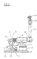
- the positioning apparatus comprises a base 10 onto which is mounted a rotatable turret 11.
- a transmission 12 is, in turn, mounted onto turret 11.
- a rotary power source 14, here an electric motor, is arranged to drive the transmission 12.
- a shaft encoder 16 and a tachometer 18 are operatively connected with the rotary power source 14 for providing output indications of position and rotary velocity respectively of the rotary power source 14.
- the transmission 12 comprises a harmonic drive gear 20, such as one available from Harmonic Drive GmbH, of Langen, West Germany, and includes a circular spline 21 fixed to the transmission housing, wave generator 22, which is mounted onto the output shaft 24 of the rotary power source 14 for rotation together therewith and a felxspine 26 onto which is mounted a transmission output shaft 28, which is bearing mounted onto bearings 30 within a transmission housing 32.
- a harmonic drive gear 20 such as one available from Harmonic Drive GmbH, of Langen, West Germany
- wave generator 22 which is mounted onto the output shaft 24 of the rotary power source 14 for rotation together therewith
- a felxspine 26 onto which is mounted a transmission output shaft 28, which is bearing mounted onto bearings 30 within a transmission housing 32.
- thermocouple 31 is typically mounted onto the interior of the housing of the rotary power source 14.
- thermocouple 33 is typically mounted in communication with the interior of the transmission housing 32 for providing a temperature output indication.
- An elongate first arm 34 is mounted onto output shaft 28.
- a load 36 is held at the extreme end of arm 34, as by a gripper 38.
- the term load is used throughout to indicate a specific location whose position, velocity and force is to be determined in accordance with the present invention.
- force is deemed to be broad enough to include torque.
- the load may be, as illustrated, external to the positioning apparatus, or alternatively, in certain cases, may be a location on the positioning apparatus itself.
- a motor driver such as a HS 220-6 available from Harmonic Drive GmbH, is shown at reference numeral 37 and is seen to be associated with logic circuitry 39, a current transducer 40 and a power supply 41.
- Fig. 4 illustrates the operation of the apparatus illustrated in Figs. 1 - 3 and particularly the logic circuitry 39.
- the input power I m of the driving apparatus is measured or alternatively determined by a controller 43 having an output I c which is supplied to an OR gate 45.
- the OR gate 45 selects either I m or I c according to which is available and provides an output I representing the current supplied to the driving apparatus 14.
- the input power I m may be measured by an current transducer 40 such as a DC current sensor commercially available from American Aerospace Controls Inc. of Farmingdale New York, which measures the input electrical current to the motor.
- the position P of the driving apparatus is also measured, in the illustrated example, by shaft encoder 16.
- the measured velocity V m of the driving apparatus is measured by the tachometer 18 and the measured acceleration A m of the driving apparatus is calculated from the velocity. Alternatively it may be measured by an angular accelerator (not shown).
- the temperature T1° of the driving apparatus is also measured in the preferred embodiment of the invention by a thermocouple 31.
- the temperature T2° of the transmission is also measured in the preferred embodiment of the invention by a thermocouple 33.
- measurements of either or both of the parameters A m and T° may be eliminated.
- V c can be calculated from the position in accordance with the following simplified first order expression: where T is the time between two measurements of P and t is the time of the second measurement of P
- a logic OR function 52 selects either V m or V c according to which is available and provides an output V representing the velocity of the driving apparatus.
- the measured or calculated value of V may be supplied to an acceleration calculation circuit 53 which provides an output representing a calculated value of the acceleration of the driving apparatus A c in accordance with the following simplified first order expression: where T is the time between two measurements of V and t is the time of the second measurement of V
- a logic OR function 54 selects either A m or A c according to which is available and provides an output A representing the velocity of the driving apparatus.
- the parameters input power I, position P, velocity V, acceleration A and normally temperature of the driving apparatus and of the transmission T1°, T2° are supplied to logic circuitry 56 which provides output indications PL, VL, AL and TL which represent the position, velocity and acceleration respectively of the load 36, and the torque or force of the output of the transmission 12.
- the term "force" is deemed to be broad enough to include torque.
- Condition A is represented by the following expression: ⁇ G I + H V + J A + K (Sign V) ⁇ (Sign V) ⁇ 0 (3)
- Condition B is represented by the following expressions: ⁇ G I + H V + J A + K (Sign V) ⁇ (Sign V) ⁇ 0 (4) and ⁇ L I + M V + N A + Q (Sign V) ⁇ (Sign V) ⁇ C1 (5)
- Condition C is represented by the following expressions: ⁇ G I + H V + J A + K (Sign V) ⁇ (Sign V) ⁇ 0 (4) and ⁇ L I + M V + N A + Q (Sign V) ⁇ (Sign V) ⁇ C1 (6)
- G, H, J, K, L, M, N, C1 and Q are all temperature dependent constants.
- the input power I is changed until V just becomes not equal to zero and then the above process is carried out.
- the input power I may be changed in a first direction until V just becomes not equal to zero.
- the start up torque in a first direction is determined in accordance with the following expression: T1 is proportional to GI (16) The current which satisfies this expression is termed I1.
- the input power I is then changed in a second direction until V once again just becomes not equal to zero.
- the start up torque in a second direction is determined in accordance with the following expression: T2 is proportional to GI (17)
- I2 The current which satisfies this expression is termed I2.
- the driving apparatus When the driving apparatus is driving the load, and when the load is driving the driving apparatus, the direction and size of the required backlash correction is known and included in the PL, TL and VL outputs. If neither the load is driving the driving apparatus nor the driving apparatus is driving the load, then the PL, TL and VL outputs make an appropriate correction based on a knowledge of the previous direction of movement.
- the driving apparatus 14, shaft encoder 16 and tachometer 18 are embodied in a HT-25-3014-TE-500Z available from Harmonic Drive GmbH, of Langen, West Germany.
- the servo amplifier 37, serving as the driver for driving apparatus 14 is a HS-220-6 and the transformer 41 is a PT 656S, also available from Harmonic Drive GmbH.
- the stiffness coefficient K s of the transmission is 14,500 Newton-meter/radian.
- the first arm 34 may either be a rigid arm having a length of 800 mm, a weight of 6 Kg, and a stiffness coefficient K s of 70,500 Newton-meter/radian, or a flexible arm having a length of 800 mm, a weight of 800 gram, and a stiffness coefficient K s of 315 Newton-meter/radian.
- a is a constant (dimensionless) which represents the fact that the rotary power source 14 is driving the load and is dependent on the temperature of the transmission 12, as measured by thermocouple 33; r is the gear ratio (dimensionless) of transmission 12; B m is the motor viscosity factor of the rotary power source 14 related to the output of the harmonic drive transmission 12, expressed in Newton-meter/radian/sec; B a is part of the viscosity factor of the harmonic drive transmission 12, related to the output of the harmonic drive transmission, when the rotary power source 14 is driving the load, expressed in Newton-meter/radian/sec; T fm is the motor columbic friction of the rotary power source 14 related to the output of the harmonic drive transmission 12, expressed in Newton-meter; and T a is part of the harmonic drive transmission coloumbic friction of transmission 12, related to the output of the harmonic drive transmission, when the rotary power source 14 is driving the load, expressed in Newton-meter.
- the apparatus of Figs. 1 - 3 is operated at constant velocity V from an orientation where the first arm 34 is generally horizontal moving up through about 45 degrees, in both clockwise and anti-clockwise directions, such that it is certain that the rotary power source 14 is driving the load.
- V input power in amperes
- V rotary power source velocity in radian/sec
- P position of the power source given by shaft encoder 16 in radians
- T ext mass of first arm 34 x distance of center of gravity from the center of rotation x g (gravitational constant) x cosine of the position of the first arm. (25) where the horizontal position is deemed to be at zero degrees and the upwards rotation in a counterclockwise direction is deemed to be of positive sign.
- the constant J can be found by an empirical process as follows:
- the apparatus of Figs. 1 - 3 is operated at constant acceleration A from an orientation where the first arm 34 is generally horizontal moving up through about 45 degrees, in both clockwise and anti-clockwise directions, such that it is certain that the rotary power source 14 is driving the load.
- I input power in amperes
- V rotary power source velocity in radian/sec
- P position of the power source given by shaft encoder 16 in radians
- V can be used to provide an indication of acceleration using equation (2).
- the above initialization procedures are carried out for a multiplicity of different temperatures to enable extrapolation or interpolation of the parameters for all temperatures T1° and T2° over a given range.
- b is a constant (dimensionless) which represents the fact that the load is driving the rotary power source and is dependent on the temperature of the transmission 12, as measured by thermocouple 33;
- B b is part of the viscosity factor of the harmonic drive transmission 12, related to the output of the harmonic drive tarnsmission, when the load is driving the rotary power source 14, expressed in Newton-meter/radian/sec;
- T b is part of the harmonic drive transmission coloumbic friction of transmission 12, related to the output of the harmonic drive transmission, when the load is driving the rotary power source 14, expressed in Newton
- the apparatus of Figs. 1 - 3 is operated at constant velocity V from an orientation where the first arm 34 is generally horizontal moving down through about - 45 degrees, in both clockwise and anti-clockwise directions, such that it is certain that the load is driving the rotary power source 14.
- V input power in amperes
- V rotary power source velocity in radian/sec
- P position of the power source given by shaft encoder 16 in radians
- T ext must be calculated for each sample in accordance with expression (25), where the horizontal position is deemed to be at zero degrees and the downwards rotation in a clockwise direction is deemed to be of negative sign.
- the constant N can be found by an empirical initialization process as follows:
- the apparatus of Figs. 1 - 3 is operated at constant acceleration A from an orientation where the first arm 34 is generally horizontal moving down through about - 45 degrees, in both clockwise and anti-clockwise directions, such that it is certain that the load is driving the rotary power source 14.
- I input power in amperes
- V rotary power source velocity in radian/sec
- P position of the power source given by shaft encoder 16 in radians
- V can be used to provide an indication of acceleration using equation (2).
- temperature dependent constant C1 dimensioned in Newton-meter, can be determined by the following initialization procedure:
- the apparatus of Figs. 1 - 3 is operated at constant velocity V from an orientation where the first arm 34 is generally oriented at 45 degrees above the horizontal moving up until it reaches a generally vertical orientation, in either or both clockwise and anti-clockwise directions, such that it is certain that the rotary power source 14 is driving the load.
- V input power in amperes
- V rotary power source velocity in radian/sec
- P position of the power source given by shaft encoder 16 in radians
- the unbalance moment T ext of the first arm 34 is given by expression (25).
- Equation (7) the function R can be given by the following simplified first order expression: where K s is the equivalent stiffness coefficient of the first arm and of the harmonic drive transmission, expressed in Newton-meter/radian.
- K s can determine empirically by applying a predetermined force perpendicular to a vertically directed first arm 34 at the location of the load and measuring the difference in angular orientation D A of the load location between cases when the force is present and when it is absent using a closed position loop control on the driving apparatus to hold it in position.
- Fig. 9A illustrates the first arm 34 prior to application of force thereto.
- Fig. 9b illustrates the deflection of the first arm 34 due to the lack of stiffness of the transmission.
- Fig. 9C illustrates the deflection shown in Fig. 9B and in addition thereto, the additional deflection produced by the flexibility of the arm.
- This initialization procedure is carried out over a range of forces in both horizontal directions to provide a table of values of K s for different values of TL.
- the function F(P) represents the linearization correction between the output of the harmonic drive transmission and the output of the shaft encoder 16 without load.
- the function F(P) is determined by the following initialization procedure which may employ the apparatus of Fig. 6. This is carried out only once upon installation of the apparatus.
- the position of the driving apparatus, sensed by the shaft encoder 16, is first zeroed to the output of the harmonic drive transmission as an absolute angle measured from the zero degree position of the output shaft.
- This zeroing may be provided by means of an up-down counter 17 receiving an output from shaft encoder 16 and a zero output form a Hall-effect sensor 35 in communication with a magnet 37 (Fig. 1) which is mounted for rotation together with the output shaft 28 of the transmission.
- a shaft encoder 52 or other suitable sensor is associated with the output of the harmonic drive transmission 12 typically via a flexible coupling 54 for the purposes of this initialization procedure only.
- a subtractor 56 receives the output P from up-down counter 17 and the output from shaft encoder 52 and provides an output representing F(P) - P.
- the rotary power source 14 is operated to cause the harmonic drive transmission output to rotate through at least about 360 degrees in both clockwise and counterclockwise directions. At sampling intervals of typically 10 msecs, in order to obtain typically about 2000 samples per revolution of the transmission output, the outputs of the shaft encoder 16 and of the shaft encoder temporarily associated with the harmonic drive transmission 12 output are measured and stored.
- a correlation table is thus prepared representing F(P), it being appreciated that two values of F are given for each value of P, the difference between them representing the backlash. The two values are typically averaged and one half of the difference is added or subtracted as appropriate, depending on whether the rotary power source is driving the load or vice versa, thus providing automatic compensation for backlash.
- This correlation table is illustrated in Fig. 7A.
- the quantity F(P) - P is illustrated in Fig. 7A for travel in clockwise and counterclockwise directions.
- the difference between the quantity F(P) - P for travel in the two opposite directions is shown in Fig. 7B and represents the backlash.
- the apparatus of Figs. 1 - 3 is operated at constant velocity V to move the first arm 34 from the angle at which C1 was found (equation 34) up through the vertical to the opposite angle as measured from the vertical in either or both clockwise or counterclockwise directions. It is noted that between these two angles neither the rotary power source 14 drives the load or vice versa.
- I input power in amperes
- V rotary power source velocity in radian/sec
- P position of the power source given by shaft encoder 16 in radians
- the constant U can be found by an empirical process as follows:
- Figs 1 - 3 The apparatus of Figs 1 - 3 is operated at constant acceleration A to move the first arm 34 from the angle at which C1 was found (equation 34) up through the vertical to the opposite angle as measured from the vertical in either or both clockwise or counterclockwise directions. It is noted that between these two angles neither the rotary power source 14 drives the load or vice versa.
- I input power in amperes
- V rotary power source velocity in radian/sec
- P position of the power source given by shaft encoder 16 in radians
- V can be used to provide an indication of acceleration using equation (2).
- Enhanced values of S, T, U and W can be realized by carrying out the initialization process additionally in the following way:
- the apparatus of Figs. 1 - 3 is operated at constant velocity V or acceleration A to move the first arm 34 from the angle symmetric bout the horizontal axis to the angle at which C1 was found (equation 34) down through the vertical to the opposite angle as measured from the vertical in either or both clockwise or counterclockwise directions.
- the inaccuracy of the load position is reduced by a factor of 1/20 to 1/50 as compared with prior art systems.
- the present invention provides typical residual error of about 0.3 milliradian (peak to peak) and does not require sensors at the output of the transmission during operation thereof.
- any transmission of known characteristics, and unknown changeable load and any arm of known stiffness coefficient K s may be employed. Appropriate load position, force, velocity and acceleration information will be provided.
- This information may be used for position correction feedback purposes to the rotary power source in a conventional way in order to provide extremely precise positioning of the load.
- dynamic tracking of the load may be realized for any desired trajectory.
- This is particularly useful in CAD/CAM applications wherein the trajectory is specified by spatial coordinates.
- the load may thus be accurately placed where indicated by the coordinates notwithstanding flexibility in the positioning apparatus and the existence of an unknown changeable load. A high level of repeatability is thereby attained even for unknown changeable loads.
- this information may be used in an open loop framework for load location. It is noted that the velocity, force and acceleration of the load can be determined in accordance with the present invention in an open loop framework.
- the present invention is also equally applicable to cases of changing load, unknown changing moment of inertia of the load and unknown changeable forces.
- a particular unknown force is the unbalanced torque of the arm, itself.
- the apparatus of the present invention is operative to indicate the position of the load even when the positioning apparatus is at rest and the overall external torque is smaller than the static friction. This is achieved by the following technique. When the load is at rest, the input power I is increased or decreased until quasi-static movement of the load is reached. Thereafter the technique set forth in Fig. 5 is then carried out, as described hereinabove.
- K s may be defined in two ways:
- K s D B /TL (44) where D B is the angular displacement of the tangent to the end of the arm 34. According to the present invention, a correction may be made on the basis of either expression (36) or expression (44) or on the basis of a desired compromise or selection therebelow.
- a second motor driven arm 80 is also provided in series with first arm 34
- the apparatus of the present invention is able to provide an accurate output indication of the position, force, velocity and acceleration of a load 82 supported on arm 80 without requiring any additional information about arm 80 or load 82 or their motion, on the assumption that arm 80 and load 82 are stiff.
- control information relative to the operation of a motor 84 driving second arm 80 need not be considered at all.
- the mass of the load can be determined for the embodiment of Figs. 1 - 3 in accordance with the present invention according to the following expression: where T ext is given by expression (25) JL is the fixed moment of inertia of the load 36 D is the distance from the center of rotation to the load 36.
- the present invention is not limited to electrical driving apparatus or to rotary driving apparatus. Any suitable type of driving apparatus may be employed.
- electrical motors of any suitable type including electrical linear motors, and pneumatic or hydraulic motors of any suitable type including linear motors may be employed.
- fluidic motors, such as pneumatic or hydraulic motors are employed, measurement of input current is replaced by a measurement of input pressure or flow.
Landscapes
- Engineering & Computer Science (AREA)
- Human Computer Interaction (AREA)
- Manufacturing & Machinery (AREA)
- Physics & Mathematics (AREA)
- General Physics & Mathematics (AREA)
- Automation & Control Theory (AREA)
- Robotics (AREA)
- Mechanical Engineering (AREA)
- Control Of Position Or Direction (AREA)
- Agricultural Machines (AREA)
Priority Applications (1)
| Application Number | Priority Date | Filing Date | Title |
|---|---|---|---|
| AT88101610T ATE76521T1 (de) | 1987-02-05 | 1988-02-04 | Vorrichtung zur genauen positionierung. |
Applications Claiming Priority (4)
| Application Number | Priority Date | Filing Date | Title |
|---|---|---|---|
| IL81487 | 1987-02-05 | ||
| IL81487A IL81487A (en) | 1987-02-05 | 1987-02-05 | Precise positioning apparatus |
| IL83854 | 1987-09-10 | ||
| IL83854A IL83854A0 (en) | 1987-09-10 | 1987-09-10 | Precise positioning apparatus |
Publications (2)
| Publication Number | Publication Date |
|---|---|
| EP0277656A1 true EP0277656A1 (de) | 1988-08-10 |
| EP0277656B1 EP0277656B1 (de) | 1992-05-20 |
Family
ID=26321644
Family Applications (1)
| Application Number | Title | Priority Date | Filing Date |
|---|---|---|---|
| EP88101610A Expired - Lifetime EP0277656B1 (de) | 1987-02-05 | 1988-02-04 | Vorrichtung zur genauen Positionierung |
Country Status (6)
| Country | Link |
|---|---|
| US (2) | US4857816A (de) |
| EP (1) | EP0277656B1 (de) |
| AU (1) | AU608803B2 (de) |
| CA (1) | CA1325665C (de) |
| DE (1) | DE3871165D1 (de) |
| ES (1) | ES2032879T3 (de) |
Cited By (4)
| Publication number | Priority date | Publication date | Assignee | Title |
|---|---|---|---|---|
| EP0593760A4 (de) * | 1990-04-05 | 1995-01-18 | Fanuc Ltd | System zur korrektur von zahnradsteigungsfehler einer numerischen steuerung. |
| EP0784252A1 (de) * | 1996-01-11 | 1997-07-16 | Systems, Machines, Automation Components Corporation | Verfahren zum weichen Absetzen einer Stiftanordnung |
| US6118360A (en) * | 1996-01-11 | 2000-09-12 | Systems, Machines, Automation Components Corporation | Linear actuator |
| EP1250986A3 (de) * | 2001-04-16 | 2006-05-17 | Fanuc Ltd | Robotersteuerung mit Mitteln zum Kompensieren von Biegungen |
Families Citing this family (20)
| Publication number | Priority date | Publication date | Assignee | Title |
|---|---|---|---|---|
| JP2703575B2 (ja) * | 1988-09-30 | 1998-01-26 | ファナック株式会社 | サーボ制御装置 |
| JP2709969B2 (ja) * | 1989-12-12 | 1998-02-04 | ファナック株式会社 | サーボモータの制御方法 |
| JP2813909B2 (ja) * | 1989-12-28 | 1998-10-22 | 東芝機械株式会社 | 数値制御装置のバックラッシュ補正方式 |
| JPH03290706A (ja) * | 1990-04-09 | 1991-12-20 | Mitsubishi Electric Corp | 数値制御装置 |
| US5889670A (en) | 1991-10-24 | 1999-03-30 | Immersion Corporation | Method and apparatus for tactilely responsive user interface |
| US5220260A (en) * | 1991-10-24 | 1993-06-15 | Lex Computer And Management Corporation | Actuator having electronically controllable tactile responsiveness |
| US5327059A (en) * | 1992-09-24 | 1994-07-05 | Archive Corporation | Tape drive capstan motor servo system with static friction compensation |
| US5724264A (en) * | 1993-07-16 | 1998-03-03 | Immersion Human Interface Corp. | Method and apparatus for tracking the position and orientation of a stylus and for digitizing a 3-D object |
| JPH08106313A (ja) * | 1994-10-07 | 1996-04-23 | Toshiba Mach Co Ltd | 数値制御工作機械における楕円曲線の創成方法 |
| DE4441240C1 (de) * | 1994-11-19 | 1996-05-09 | Leica Lasertechnik | Vorrichtung und Verfahren zur Regelung der Bewegung eines Gegenstandes |
| US6697748B1 (en) | 1995-08-07 | 2004-02-24 | Immersion Corporation | Digitizing system and rotary table for determining 3-D geometry of an object |
| US6195618B1 (en) | 1998-10-15 | 2001-02-27 | Microscribe, Llc | Component position verification using a probe apparatus |
| US6060854A (en) * | 1998-11-12 | 2000-05-09 | Vickers, Inc. | Method and apparatus for compensating for windup in a machine |
| US6298255B1 (en) | 1999-06-09 | 2001-10-02 | Aspect Medical Systems, Inc. | Smart electrophysiological sensor system with automatic authentication and validation and an interface for a smart electrophysiological sensor system |
| US20030161735A1 (en) * | 2002-02-28 | 2003-08-28 | Samsung Electronics Co., Ltd. | Apparatus and method of controlling linear compressor |
| DE102004028558A1 (de) * | 2004-06-15 | 2006-01-05 | Abb Patent Gmbh | Verfahren und Messanordnung zur Spielmessung an einem Achsgelenk |
| US7979160B2 (en) * | 2007-07-31 | 2011-07-12 | Spirit Aerosystems, Inc. | System and method for robotic accuracy improvement |
| US8473103B2 (en) * | 2009-01-27 | 2013-06-25 | Fanuc Robotics America, Inc. | Secondary position feedback control of a robot |
| GB201603283D0 (en) * | 2016-02-25 | 2016-04-13 | Johnson Electric Sa | Method of reducing noise from a HVAC system |
| DE102017211549A1 (de) * | 2017-07-06 | 2019-01-10 | Kuka Deutschland Gmbh | Verfahren zur Verschleißüberwachung eines Getriebes |
Citations (4)
| Publication number | Priority date | Publication date | Assignee | Title |
|---|---|---|---|---|
| EP0066673A2 (de) * | 1981-03-04 | 1982-12-15 | Hitachi, Ltd. | Verfahren zur Steuerung der Winkelposition und Vorrichtung dafür |
| EP0072870A1 (de) * | 1981-02-24 | 1983-03-02 | Fanuc Ltd. | Spielausgleichsystem für doppelstellungsrückkopplungssteuersysteme |
| US4580229A (en) * | 1982-10-15 | 1986-04-01 | Shin Meiwa Industry Co., Ltd. | Method and apparatus for control of an articulated robot |
| EP0148269B1 (de) * | 1983-03-04 | 1992-07-29 | Fanuc Ltd. | Servo-fahreinheit |
Family Cites Families (22)
| Publication number | Priority date | Publication date | Assignee | Title |
|---|---|---|---|---|
| CH512107A (de) * | 1970-02-10 | 1971-08-31 | Zellweger Uster Ag | Verfahren zur Regelung an Regelstrecken für unlineare Regelvorgänge, sowie Vorrichtung zur Durchführung des Verfahrens |
| US3689821A (en) * | 1971-03-09 | 1972-09-05 | Hourdaille Ind Inc | Correction system for numerical controls |
| JPS4835259A (de) * | 1971-09-10 | 1973-05-24 | ||
| US3766461A (en) * | 1971-10-04 | 1973-10-16 | Superior Electric Co | Backlash compensation circuit for numerically controlled stepping motor driven machine |
| JPS5218356B2 (de) * | 1972-02-12 | 1977-05-20 | ||
| GB1416401A (en) * | 1973-03-06 | 1975-12-03 | Rolls Royce | Control systems |
| JPS5368362A (en) * | 1976-11-29 | 1978-06-17 | Hitachi Ltd | Shock absorbing device |
| JPS54132090A (en) * | 1978-04-03 | 1979-10-13 | Fanuc Ltd | Error correction system for numerical control |
| US4249117A (en) * | 1979-05-01 | 1981-02-03 | Black And Decker, Inc. | Anti-kickback power tool control |
| JPS5776608A (en) * | 1980-10-30 | 1982-05-13 | Fanuc Ltd | Position error correction device |
| GB2090090B (en) * | 1980-12-19 | 1984-03-21 | Philips Electronic Associated | Amplifier circuit |
| US4404626A (en) * | 1981-02-02 | 1983-09-13 | Kabushiki Kaisha Sanesu Shoko | Positioning controlling method |
| JPS57196314A (en) * | 1981-05-26 | 1982-12-02 | Mitsubishi Electric Corp | Measuring device of backlash amount |
| JPS57196313A (en) * | 1981-05-26 | 1982-12-02 | Mitsubishi Electric Corp | Automatic compensating device for backlash amount |
| SU1062641A1 (ru) * | 1982-06-25 | 1983-12-23 | Белорусский Ордена Трудового Красного Знамени Государственный Университет Им.В.И.Ленина | Многоканальное псевдолинейное корректирующее устройство |
| CA1184273A (en) * | 1982-09-23 | 1985-03-19 | Kazuyoshi Yasukawa | Robot control apparatus |
| JPS59123485A (ja) * | 1982-12-29 | 1984-07-17 | Fanuc Ltd | 電流フイ−ドバツク系のオ−バ−シユ−ト防止回路 |
| JP2572564B2 (ja) * | 1983-08-22 | 1997-01-16 | 株式会社 エスジー | 電気モータの位置決め制御装置 |
| US4580299A (en) * | 1983-10-19 | 1986-04-08 | Surgidev Corp. | Intraocular lens |
| SU1179507A1 (ru) * | 1984-02-10 | 1985-09-15 | Предприятие П/Я Ю-9799 | Задающее устройство дл электропривода |
| GB2166841B (en) * | 1984-11-09 | 1988-11-02 | Ferranti Plc | Reaction force compensation |
| JP2694827B2 (ja) * | 1985-10-17 | 1997-12-24 | 東芝機械株式会社 | バックラッシュ補正方法 |
-
1987
- 1987-10-08 US US07/107,481 patent/US4857816A/en not_active Expired - Lifetime
-
1988
- 1988-01-26 US US07/148,503 patent/US4868475A/en not_active Expired - Lifetime
- 1988-02-02 CA CA000557934A patent/CA1325665C/en not_active Expired - Fee Related
- 1988-02-04 EP EP88101610A patent/EP0277656B1/de not_active Expired - Lifetime
- 1988-02-04 ES ES198888101610T patent/ES2032879T3/es not_active Expired - Lifetime
- 1988-02-04 AU AU11275/88A patent/AU608803B2/en not_active Ceased
- 1988-02-04 DE DE8888101610T patent/DE3871165D1/de not_active Expired - Lifetime
Patent Citations (4)
| Publication number | Priority date | Publication date | Assignee | Title |
|---|---|---|---|---|
| EP0072870A1 (de) * | 1981-02-24 | 1983-03-02 | Fanuc Ltd. | Spielausgleichsystem für doppelstellungsrückkopplungssteuersysteme |
| EP0066673A2 (de) * | 1981-03-04 | 1982-12-15 | Hitachi, Ltd. | Verfahren zur Steuerung der Winkelposition und Vorrichtung dafür |
| US4580229A (en) * | 1982-10-15 | 1986-04-01 | Shin Meiwa Industry Co., Ltd. | Method and apparatus for control of an articulated robot |
| EP0148269B1 (de) * | 1983-03-04 | 1992-07-29 | Fanuc Ltd. | Servo-fahreinheit |
Cited By (5)
| Publication number | Priority date | Publication date | Assignee | Title |
|---|---|---|---|---|
| EP0593760A4 (de) * | 1990-04-05 | 1995-01-18 | Fanuc Ltd | System zur korrektur von zahnradsteigungsfehler einer numerischen steuerung. |
| EP0784252A1 (de) * | 1996-01-11 | 1997-07-16 | Systems, Machines, Automation Components Corporation | Verfahren zum weichen Absetzen einer Stiftanordnung |
| US5952589A (en) * | 1996-01-11 | 1999-09-14 | Systems, Machines, Automation Components Corporation | Soft landing method for probe assembly |
| US6118360A (en) * | 1996-01-11 | 2000-09-12 | Systems, Machines, Automation Components Corporation | Linear actuator |
| EP1250986A3 (de) * | 2001-04-16 | 2006-05-17 | Fanuc Ltd | Robotersteuerung mit Mitteln zum Kompensieren von Biegungen |
Also Published As
| Publication number | Publication date |
|---|---|
| US4857816A (en) | 1989-08-15 |
| DE3871165D1 (de) | 1992-06-25 |
| ES2032879T3 (es) | 1993-03-01 |
| US4868475A (en) | 1989-09-19 |
| CA1325665C (en) | 1993-12-28 |
| EP0277656B1 (de) | 1992-05-20 |
| AU608803B2 (en) | 1991-04-18 |
| AU1127588A (en) | 1988-08-11 |
Similar Documents
| Publication | Publication Date | Title |
|---|---|---|
| US4868475A (en) | Precise positioning apparatus | |
| US12330306B2 (en) | Obtaining the gear stiffness of a robot joint gear of a robot arm | |
| US4989161A (en) | Control unit for a multi-degree-of freedom manipulator | |
| US20220226993A1 (en) | Method of controlling a robot arm based on adaptive friction | |
| EP0232424B1 (de) | Industrieller roboter | |
| US6343243B1 (en) | Method for determining load parameters for a manipulator | |
| Kuroki et al. | Cr-N alloy thin-film based torque sensors and joint torque servo systems for compliant robot control | |
| SE516720C2 (sv) | Utrustning för styrning av en industrirobot och förfarande för programmering och/eller justering av robotens rörelse | |
| US4593366A (en) | Method of controlling robot | |
| RU2037173C1 (ru) | Самонастраивающийся электропривод робота | |
| CN113711138B (zh) | 伺服控制装置 | |
| EP0201106A2 (de) | Absoluter Lagekodierer | |
| US7694588B2 (en) | Adjustment and stabilization unit with a force-sensing device for torque measurement | |
| Lightcap et al. | Dynamic identification of a mitsubishi pa10-6ce robot using motion capture | |
| Moreira et al. | First steps towards an open control architecture for a PUMA 560 | |
| Bernstein et al. | Shape change actuation for precision attitude control | |
| Ghasemi et al. | Improvement of position measurement for 6R robot using magnetic encoder AS5045 | |
| Dwolatzky et al. | The GEC Tetrabot-a serial-parallel topology robot: control design aspects | |
| Desilva et al. | Torque sensor for direct-drive manipulators | |
| Fraser et al. | An experimental single-link flexible arm | |
| WO1995007793A2 (en) | Force and position controlled manipulator | |
| JPH0612111A (ja) | ロボットアームの位置制御方法及び位置制御装置 | |
| Miková et al. | Basics of mechatronics | |
| Oda et al. | A compliant motion control of planar redundant manipulator by amplifying joint torsional deflections | |
| JPS63198105A (ja) | 位置決め装置 |
Legal Events
| Date | Code | Title | Description |
|---|---|---|---|
| PUAI | Public reference made under article 153(3) epc to a published international application that has entered the european phase |
Free format text: ORIGINAL CODE: 0009012 |
|
| AK | Designated contracting states |
Kind code of ref document: A1 Designated state(s): AT BE CH DE ES FR GB GR IT LI LU NL SE |
|
| 17P | Request for examination filed |
Effective date: 19881229 |
|
| 17Q | First examination report despatched |
Effective date: 19900821 |
|
| RBV | Designated contracting states (corrected) |
Designated state(s): AT BE CH DE ES FR GB IT LI LU NL SE |
|
| GRAA | (expected) grant |
Free format text: ORIGINAL CODE: 0009210 |
|
| AK | Designated contracting states |
Kind code of ref document: B1 Designated state(s): AT BE CH DE ES FR GB IT LI LU NL SE |
|
| REF | Corresponds to: |
Ref document number: 76521 Country of ref document: AT Date of ref document: 19920615 Kind code of ref document: T |
|
| ITF | It: translation for a ep patent filed | ||
| ET | Fr: translation filed | ||
| REF | Corresponds to: |
Ref document number: 3871165 Country of ref document: DE Date of ref document: 19920625 |
|
| REG | Reference to a national code |
Ref country code: ES Ref legal event code: FG2A Ref document number: 2032879 Country of ref document: ES Kind code of ref document: T3 |
|
| PLBE | No opposition filed within time limit |
Free format text: ORIGINAL CODE: 0009261 |
|
| STAA | Information on the status of an ep patent application or granted ep patent |
Free format text: STATUS: NO OPPOSITION FILED WITHIN TIME LIMIT |
|
| 26N | No opposition filed | ||
| EPTA | Lu: last paid annual fee | ||
| EAL | Se: european patent in force in sweden |
Ref document number: 88101610.9 |
|
| PGFP | Annual fee paid to national office [announced via postgrant information from national office to epo] |
Ref country code: GB Payment date: 19970205 Year of fee payment: 10 |
|
| PGFP | Annual fee paid to national office [announced via postgrant information from national office to epo] |
Ref country code: FR Payment date: 19970207 Year of fee payment: 10 |
|
| PGFP | Annual fee paid to national office [announced via postgrant information from national office to epo] |
Ref country code: SE Payment date: 19970211 Year of fee payment: 10 |
|
| PGFP | Annual fee paid to national office [announced via postgrant information from national office to epo] |
Ref country code: ES Payment date: 19970220 Year of fee payment: 10 |
|
| PGFP | Annual fee paid to national office [announced via postgrant information from national office to epo] |
Ref country code: AT Payment date: 19970225 Year of fee payment: 10 |
|
| PGFP | Annual fee paid to national office [announced via postgrant information from national office to epo] |
Ref country code: NL Payment date: 19970228 Year of fee payment: 10 |
|
| PGFP | Annual fee paid to national office [announced via postgrant information from national office to epo] |
Ref country code: CH Payment date: 19970317 Year of fee payment: 10 Ref country code: BE Payment date: 19970317 Year of fee payment: 10 |
|
| PGFP | Annual fee paid to national office [announced via postgrant information from national office to epo] |
Ref country code: LU Payment date: 19970320 Year of fee payment: 10 |
|
| PG25 | Lapsed in a contracting state [announced via postgrant information from national office to epo] |
Ref country code: LU Free format text: LAPSE BECAUSE OF NON-PAYMENT OF DUE FEES Effective date: 19980204 Ref country code: GB Free format text: LAPSE BECAUSE OF NON-PAYMENT OF DUE FEES Effective date: 19980204 Ref country code: AT Free format text: LAPSE BECAUSE OF NON-PAYMENT OF DUE FEES Effective date: 19980204 |
|
| PG25 | Lapsed in a contracting state [announced via postgrant information from national office to epo] |
Ref country code: SE Free format text: LAPSE BECAUSE OF NON-PAYMENT OF DUE FEES Effective date: 19980205 Ref country code: ES Free format text: LAPSE BECAUSE OF EXPIRATION OF PROTECTION Effective date: 19980205 |
|
| PG25 | Lapsed in a contracting state [announced via postgrant information from national office to epo] |
Ref country code: LI Free format text: LAPSE BECAUSE OF NON-PAYMENT OF DUE FEES Effective date: 19980228 Ref country code: FR Free format text: THE PATENT HAS BEEN ANNULLED BY A DECISION OF A NATIONAL AUTHORITY Effective date: 19980228 Ref country code: CH Free format text: LAPSE BECAUSE OF NON-PAYMENT OF DUE FEES Effective date: 19980228 Ref country code: BE Free format text: LAPSE BECAUSE OF NON-PAYMENT OF DUE FEES Effective date: 19980228 |
|
| PGFP | Annual fee paid to national office [announced via postgrant information from national office to epo] |
Ref country code: DE Payment date: 19980424 Year of fee payment: 11 |
|
| BERE | Be: lapsed |
Owner name: COHEN ILAN Effective date: 19980228 Owner name: ROGOZINSKI JOSEPH Effective date: 19980228 |
|
| PG25 | Lapsed in a contracting state [announced via postgrant information from national office to epo] |
Ref country code: NL Free format text: LAPSE BECAUSE OF NON-PAYMENT OF DUE FEES Effective date: 19980901 |
|
| GBPC | Gb: european patent ceased through non-payment of renewal fee |
Effective date: 19980204 |
|
| REG | Reference to a national code |
Ref country code: CH Ref legal event code: PL |
|
| EUG | Se: european patent has lapsed |
Ref document number: 88101610.9 |
|
| NLV4 | Nl: lapsed or anulled due to non-payment of the annual fee |
Effective date: 19980901 |
|
| REG | Reference to a national code |
Ref country code: FR Ref legal event code: ST |
|
| PG25 | Lapsed in a contracting state [announced via postgrant information from national office to epo] |
Ref country code: DE Free format text: LAPSE BECAUSE OF NON-PAYMENT OF DUE FEES Effective date: 19991201 |
|
| REG | Reference to a national code |
Ref country code: ES Ref legal event code: FD2A Effective date: 20000201 |
|
| PG25 | Lapsed in a contracting state [announced via postgrant information from national office to epo] |
Ref country code: IT Free format text: LAPSE BECAUSE OF NON-PAYMENT OF DUE FEES;WARNING: LAPSES OF ITALIAN PATENTS WITH EFFECTIVE DATE BEFORE 2007 MAY HAVE OCCURRED AT ANY TIME BEFORE 2007. THE CORRECT EFFECTIVE DATE MAY BE DIFFERENT FROM THE ONE RECORDED. Effective date: 20050204 |