EP0277683A2 - Procédé et appareil pour appliquer des forces à des feuilles de verre, en particulier à haute température - Google Patents
Procédé et appareil pour appliquer des forces à des feuilles de verre, en particulier à haute température Download PDFInfo
- Publication number
- EP0277683A2 EP0277683A2 EP88200118A EP88200118A EP0277683A2 EP 0277683 A2 EP0277683 A2 EP 0277683A2 EP 88200118 A EP88200118 A EP 88200118A EP 88200118 A EP88200118 A EP 88200118A EP 0277683 A2 EP0277683 A2 EP 0277683A2
- Authority
- EP
- European Patent Office
- Prior art keywords
- glass sheet
- gas
- wall
- pressure
- practical embodiment
- Prior art date
- Legal status (The legal status is an assumption and is not a legal conclusion. Google has not performed a legal analysis and makes no representation as to the accuracy of the status listed.)
- Granted
Links
Images

Classifications
-
- C—CHEMISTRY; METALLURGY
- C03—GLASS; MINERAL OR SLAG WOOL
- C03B—MANUFACTURE, SHAPING, OR SUPPLEMENTARY PROCESSES
- C03B23/00—Re-forming shaped glass
- C03B23/02—Re-forming glass sheets
- C03B23/023—Re-forming glass sheets by bending
- C03B23/035—Re-forming glass sheets by bending using a gas cushion or by changing gas pressure, e.g. by applying vacuum or blowing for supporting the glass while bending
- C03B23/0352—Re-forming glass sheets by bending using a gas cushion or by changing gas pressure, e.g. by applying vacuum or blowing for supporting the glass while bending by suction or blowing out for providing the deformation force to bend the glass sheet
- C03B23/0357—Re-forming glass sheets by bending using a gas cushion or by changing gas pressure, e.g. by applying vacuum or blowing for supporting the glass while bending by suction or blowing out for providing the deformation force to bend the glass sheet by suction without blowing, e.g. with vacuum or by venturi effect
-
- B—PERFORMING OPERATIONS; TRANSPORTING
- B65—CONVEYING; PACKING; STORING; HANDLING THIN OR FILAMENTARY MATERIAL
- B65G—TRANSPORT OR STORAGE DEVICES, e.g. CONVEYORS FOR LOADING OR TIPPING, SHOP CONVEYOR SYSTEMS OR PNEUMATIC TUBE CONVEYORS
- B65G47/00—Article or material-handling devices associated with conveyors; Methods employing such devices
- B65G47/74—Feeding, transfer, or discharging devices of particular kinds or types
- B65G47/90—Devices for picking-up and depositing articles or materials
- B65G47/91—Devices for picking-up and depositing articles or materials incorporating pneumatic, e.g. suction, grippers
- B65G47/911—Devices for picking-up and depositing articles or materials incorporating pneumatic, e.g. suction, grippers with air blasts producing partial vacuum
-
- C—CHEMISTRY; METALLURGY
- C03—GLASS; MINERAL OR SLAG WOOL
- C03B—MANUFACTURE, SHAPING, OR SUPPLEMENTARY PROCESSES
- C03B23/00—Re-forming shaped glass
- C03B23/02—Re-forming glass sheets
- C03B23/023—Re-forming glass sheets by bending
- C03B23/035—Re-forming glass sheets by bending using a gas cushion or by changing gas pressure, e.g. by applying vacuum or blowing for supporting the glass while bending
-
- C—CHEMISTRY; METALLURGY
- C03—GLASS; MINERAL OR SLAG WOOL
- C03B—MANUFACTURE, SHAPING, OR SUPPLEMENTARY PROCESSES
- C03B27/00—Tempering or quenching glass products
- C03B27/04—Tempering or quenching glass products using gas
- C03B27/0404—Nozzles, blow heads, blowing units or their arrangements, specially adapted for flat or bent glass sheets
-
- C—CHEMISTRY; METALLURGY
- C03—GLASS; MINERAL OR SLAG WOOL
- C03B—MANUFACTURE, SHAPING, OR SUPPLEMENTARY PROCESSES
- C03B35/00—Transporting of glass products during their manufacture, e.g. hot glass lenses, prisms
- C03B35/14—Transporting hot glass sheets or ribbons, e.g. by heat-resistant conveyor belts or bands
- C03B35/145—Transporting hot glass sheets or ribbons, e.g. by heat-resistant conveyor belts or bands by top-side transfer or supporting devices, e.g. lifting or conveying using suction
- C03B35/147—Transporting hot glass sheets or ribbons, e.g. by heat-resistant conveyor belts or bands by top-side transfer or supporting devices, e.g. lifting or conveying using suction of the non-contact type
-
- B—PERFORMING OPERATIONS; TRANSPORTING
- B65—CONVEYING; PACKING; STORING; HANDLING THIN OR FILAMENTARY MATERIAL
- B65G—TRANSPORT OR STORAGE DEVICES, e.g. CONVEYORS FOR LOADING OR TIPPING, SHOP CONVEYOR SYSTEMS OR PNEUMATIC TUBE CONVEYORS
- B65G2249/00—Aspects relating to conveying systems for the manufacture of fragile sheets
- B65G2249/04—Arrangements of vacuum systems or suction cups
- B65G2249/045—Details of suction cups suction cups
-
- C—CHEMISTRY; METALLURGY
- C03—GLASS; MINERAL OR SLAG WOOL
- C03B—MANUFACTURE, SHAPING, OR SUPPLEMENTARY PROCESSES
- C03B2225/00—Transporting hot glass sheets during their manufacture
- C03B2225/02—Means for positioning, aligning or orientating the sheets during their travel, e.g. stops
Definitions
- the present invention is concerned with a process, and the related device, for applying tensile forces, without any contact with solid walls, to glass sheets, in particular at a high temperature, in the operations of processing of the same glass sheets, and, more specifically, in the steps of cutting, grinding, transfer, heating, cooling, bending at a high temperature, and tempering.
- the process and the related device can be applied, in particular, in the manufacturing of glass sheets for vehicles in general, or, specifically, of cars windows, of either tempered or laminated type.
- These glass sheets must be generally manufactured with a high accuracy, both as regards their end geometry (wherein very narrow tolerances are allowed), and as regards the absence of optical distorsions or of any kinds of scratches.
- the absence of scratches is very important not only in the glass sheets, but also in any layers bonded to them such as metal coatings, silk-printed patterns of heated backlights, black or coloured stripes, trademarks, and so forth.
- the dimensional accuracy and the absence of distorsions and/or scratches in the glass sheets require that the glass sheets are treated with great care during the processing steps, above all at high temperatures, when the glass is in a more easily deformable condition, because of the decrease in its viscosity.
- the system of supporting (and/or transferring) the glass sheet with a continuous gaseous bed - with air blown from the bottom - is well known and applied, wherein the glass sheet precisely lays (and/or is moved) on a continuous cushion of air blown through a solid wall, either porous, or with many holes.
- This system is characterized in that the air pressure between the above said wall and the glass sheet is always higher, on the average, than the atmospheric (ambient) pressure. Said overpressure (with the aid of possible side supports, also useful for moving the glass sheet) balances the weight of the glass sheet.
- Said system does not make it possible to apply to the glass sheet, e.g., downwards-directed forces, or to support the same glass sheet from the top, i.e., with the wall being positioned opposite to the upper face (relatively to the gravity force) of the glass sheet. Therefore, it is not possible to easily transfer the glass sheet on a mould, or on a forming ring, or also pick it from conveyor rolls.
- the supporting by means of a solid, either porous or perforated, wall, located in the upper side, is carried out by resorting to an air suction through the same wall, by means of the application of a vacuum above it, so as to provide a vacuum between the wall and the glass sheet, which balances the weight of this latter.
- the glass sheet can be also supported from atop, by blowing a gas between the glass sheet and the wall, instead of sucking ambient air, and hence with the presence, in this case too, of a gas cushion, which prevents the glass sheet-wall contact from taking place.
- a gas cushion which prevents the glass sheet-wall contact from taking place.
- the present invention consists in the process and in the related device for applying tensile forces, with no contact with solid walls, to glass sheets, in particular at a high temperature, characterized in that a gas is blown between the glass sheet and a wall closely approached, and approximately parallel, to it, in such a way that between the two a gas cushion is established, which generates a mutual coupling force.
- gas also a vapour at a relatively high temperature is meant.
- “mutual coupling force” it is understood that the force, if applied by the device to the glass sheet, is oriented from the glass sheet towards the same device (i.e., it is a tensile force applied to the glass sheet); the force applied by the glass sheet to the device is therefore oriented from the device towards the glass sheet.
- the two forces, of action and reaction are therefore oriented in the directions which tend to couple the glass sheet and the device.
- pressure on the average lower than ambient pressure it is meant that the pressure integral extended to the surface area between the wall and the glass sheet (including the gas feed bore) is smaller than the product of said surface area by the ambient pressure. Under conditions of weight force balancing, the difference between these two amounts equals the same weight force. If, by starting from these conditions, the wall is shifted upwards, the gas cushion reaches a pressure level which is lower than the previous one, and therefore applies to the glass sheet a larger tensile force.
- the gas cushion is not only capable of supporting the glass sheet, but also of pulling it in a direction perpendicular to the surface of the same glass sheet.
- the tensile force is in fact always perpendicular to the glass sheet.
- Figures 1 and 2 show the device of the invention, in its simplest form of practical embodiment, wherein the wall is constituted by a flat circular flange 2, provided with a bore 8 located in the nearby of its centre, through which a gas is blown.
- the gas is fed through the channel 15 provided inside the stem 1, more or less rigidly connected with the flange 2, and whose outer diameter can be larger than, smaller than, or equal to, the diameter of the flange 2. If the pressure p o of the gas inside the channel 15 is high enough, and the distance between the flange 2 and the glass sheet 6 is short enough, the weight of the glass sheet 6 can be balanced by the depressure (pressure lower than ambient pressure) which is generated inside the air gap 11 between the glass sheet and the flange. In other terms, the flange pulls the glass sheet.
- the gas stream reaches a high speed in the nearby of the inner edge 9 (located at the distance r i from the axis of the bore 8) of the flange 2.
- the arrows inside the air gap show the direction of gas motion.
- the curve 23 of the chart of Figure 3 (which qualitatively describes the behaviour of the gas speed V as a function of the distance r from the axis of the bore 8) shows that, as the gas moves from the inner edge 9 towards the outer edge 19 (placed at the distance r e from the axis of the bore 8) of the flange 2, the speed of the same gas decreases, because the surface area of the section between the wall and the glass sheet, through which it flows, progressively increases. Therefore, if the pressure losses of the gas inside the air gap are smaller than the pressure recovery due to the decrease in its speed, in as much as at the outer edge 19 the gas practically reaches the ambient pressure, the same gas inside the air gap 11 is at a pressure which, on the average, is lower than ambient pressure.
- the phenomenology is slightly more complex if the radial symmetry is absent (i.e., the flange 2 and/or the bore 8 are not circular), or the motion of the gas is supersonic, with the possible presence of shock waves.
- the geometry of the device is not very different from that described, and if the gas feed pressure p o is high enough, the resulting effect is practically the same.
- the coupling force is generally stable because small increases in the distance between the surfaces 16 and 14 (e.g., downwards movements of the glass sheet) increase the depressure level inside the air gap (i.e., the force acting on the glass sheet tends to bring it back upwards) and vice-versa.
- the stability is mainly bound to the pressure losses occurring in the motion of the gas inside the air gap 11.
- the coupling force exists also if the device is located under the glass sheet in the meaning that, differently from the case of the continuous air cushion already known from the prior art, when the device is moved downwards, the glass sheet accelerates with an acceleration which is higher than that of gravity.
- the glass sheet and the device are stationary, inside the air gap 11 a pressure is established, which on the average is higher than the ambient pressure necessary to balance the weight of the glass sheet.
- the device is pulled downwards, it applies, in its turn, a downwards-directed tensile force to the glass sheet, because, under such conditions, inside the air gap 11 a pressure is established, which is considerably lower than ambient pressure. This is true for a constrained sheet too, as well as for a glass sheet at a high temperature, when it is not rigid, but deformable.
- the coupling force does not exist if the distance between the surfaces 14 and 16 of Figure 1 is long. In that case, the gas jet pushes back the glass sheet.
- the coupling takes place only when such distance is shorter than a certain value which is, above all, a function of the geometry of the device.
- Figure 5 shows a form of practical embodiment of the device of Figure 1, characterized in that the surface 16 of the flange 2, although is nearly flat, is not perfectly parallel to the upper surface 14 of the glass sheet, but has a slightly cone-frustum shape.
- it can be advantageous to give the whole surface 16, or a portion thereof, a slightly cone-frustum shape, or, generally, a non-flat shape (i.e., with a prefixed outline), both in order to optimize the pressure distribution on the glass sheet, and to decrease the pressure losses.
- the process is characterized in fact in that the sections through which the gas flows inside the air gap 11 have to increase, on the average, in the direction of movement, i.e., in such a way as to make it possible the gas speed to decrease and the consequent recovery of pressure to be achieved, which generates the coupling force between the device and the glass sheet. Therefore, also non-circular geometries of the bore and/or of the flange, are possible; in particular, the flange and/or the bore can have a polygonal or elliptical shape.
- Figure 6 shows a form of practical embodiment of the geometry of the gas feed bore 8, which is characterized by the pesence of the cone-frustum chamfer 81, which makes it possible the gas to better enter the air gap 11.
- Other shapes, not shown in Figure 6, are possible for the chamfer, in order to improve such gas entering; an example thereof is the rounded chamfer of Figure 8c.
- Figure 7 shows a form of practical embodiment of the gas feed to the air gap 11 characterized by the presence of a plurality of gas feed channels 82 which branch off the main channel 15.
- This form of practical embodiment like those relating to the following Figures 8a, 8b and 8c, shows the advantage that the gas is better distributed inside the air gap 11.
- the channels 82 can be inclined relatively to the axis of the channel 15, as shown in Figure 7, or they can be parallel, or even skew, to it.
- Figures 8a, 8b and 8c show that these drawbacks can be overcome by placing in the nearby of the gas feed bore either chamfered or not), a gas diverting baffle 24, in order to limit the gas flow rate, and/or generate an annular stream, which does not directly impinge onto the glass sheet, but tends, already since the beginning, to lap the surface 16.
- the diverting baffle 24 can be located both lined-up with, and above (Figure 8b), or under ( Figures 8a and 8c) the gas feed bore 8, and can be supported by the support 21 of Figures 8a and 8b, or by the spokes 20 of Figure 8c.
- the baffle 24 can be shifted, e.g., by moving the support 21, and such possibility can be used in order to change the coupling force between the device and the glass sheet, in particular during the glass sheet release step.
- a correct fluiddynamic design of the baffle 24 can decrease the force which pushes downwards the glass sheet in correspondence of the bore 8 (see Figure 4), or it can even generate in this region a pressure which is lower than the ambient pressure.
- the baffle 24 can extend to the whole cross-section area of the bore 8, provided that it is wholly or partially realized from a porous material, which allows the gas to flow through.
- the diverting baffle 24 can be mounted both with its lower face being lined-up with the surface 16, and slightly above, or slightly under it, by a few tenth of a millimetre.
- the device When the lower face of the diverting baffle 24 is placed at 0.1 mm below the surface 16, the device is capable of safely supporting, from atop, a circular glass sheet having a diameter of 100 mm and a weight of 90 g, with a flow rate of room-temperature air slightly larger than 4 m3/hour, fed under a pressure p o of approximately 0.1 atm gauge.
- the thickness of the air gap 11 results to be of approximately 0.25 mm.
- the glass sheet is still supported by the device (with a greater reliability), and the thickness of the air gap 11 results of approximately 0.20 mm.
- the reliability of glass sheet supporting furthermore increases (in the meaning that random forces which may add to the weight force will not cause the glass sheet to move away from the device in the vertical direction) and the thickness of the air gap slightly decreases.
- the region of the air gap 11 lying under the diverting baffle 24 is actually at a pressure lower than ambient pressure (depressure). Such depressure the higher, the higher the gas supply pressure p o .
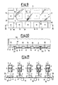
- Figure 9 shows a plurality of devices accomplished on a plate, some of which act on a shaped glass sheet.
- the whole of Figure 9 is shown from the bottom, and Figure 10 is a sectional view of the plate according to path X-X of Figure 9.
- the devices 2 are provided on the plate 37, upstream which a gas supply chamber 32 is present (this latter chamber can be replaced by a set of pipes, not shown in the figures, which feed the channels 15).
- Figure 9 shows that, in this case, the devices 2 have a square shape, and between them the channels for blown gas venting 31 are provided.
- the number of the devices is larger than the number of devices which are necessary for supporting the glass sheet shown in Figure 9, to make it possible the equipment to be used also in case of larger glass sheets.
- the coupling force is only accomplished when the glass sheet is very close to the plate, and the gas is blown through the feed bores 8, which can also be fed in an uneven way.
- the release of the glass sheet takes place by decreasing the gas flow rate through the bores 8, or, in particular, by reducing it to zero. If the glass sheet is hot, the blown gas can be heated in its turn to a suitable temperature, in order to prevent it from cooling.
- the device balances, with its tensile force, only the component of the weight force which is perpendicular to the face 16, because in the tangential direction (parallel to said face), the gas cushion is unable to exert any forces, but the very weak friction force.
- stop elements 33 In order to balance the tangential component, other forces are therefore necessary, which, e.g., in case of Figures 9 and 10, are applied by the stop elements 33 whose purpose is of not allowing the glass sheet to slip laterally.
- the stop elements 33 or similar apparatuses, can also be used, if they are movable in a direction parallel to that of the face 16, in order to supply the glass sheet with motion.
- Figure 11 shows an example of practical embodiment of a set of devices which make it possible a hot glass sheet to be picked from conveyor rolls, it to be bent and it to be possibly cooled.
- the stop elements 33 which, in a different form of practical embodiment, not shown, can come as well from the top, or from the sides of the glass sheet
- the gas in this case, hot gas
- the gas applies a thrust to the pistons 3 which, by means of the stems 1, lower the flanges 2 until these latter come close to the glass sheet.
- the gas by outflowing through the bores 8 (in that the pistons 3, the stems 1 and the flanges 2 are so bored, as to allow the gas to reach the air gap 11), accomplishes the mutual coupling of the glass sheet and the devices.
- the springs 7 contained inside the cylinders 5 serve to initially keep the flanges 2 in a lifted position, not shown in Figure, to make it possible the glass sheet to run through, before the coupling takes place.
- the sinking of the flanges 2 can anyway be controlled, according to a different form of practical embodiment not shown in figure, by adequate mechanisms.
- the springs 7 can be replaced as well by gas cushions, or by other mechanisms, which also are not shown in figure.
- the coupling between the glass sheet and the devices can be accomplished, or made easier, by analogous devices, or by gas jets, coming from down, through the free spaces between the rolls, which urge the glass sheet upwards.
- the glass sheet-devices coupling force is generated, the glass sheet can be lifted, by means of mechanisms not shown in figure, making the flanges 2 uniformly translate upwards; furthermore, by providing said flanges with translational and revolutionary movements which are different from one another, it is possible to bend the glass sheet above the conveyor rolls until it reaches a desired shape which is different from the nearly flat initial shape.
- the devices can move the glass sheet to a tempering area.
- the devices of the type as shown in Figure 11 can be located under, rather than above, the glass sheet, and act through the free spaces between the rollers.
- the coupling forces between the glass sheet and the devices make it possible the glass sheet to be bent to a desired shape, which is not possible in the support system by the continuous air cushion with air blown from down upwards.
Landscapes
- Chemical & Material Sciences (AREA)
- Engineering & Computer Science (AREA)
- Materials Engineering (AREA)
- Organic Chemistry (AREA)
- Physics & Mathematics (AREA)
- Thermal Sciences (AREA)
- Mechanical Engineering (AREA)
- Re-Forming, After-Treatment, Cutting And Transporting Of Glass Products (AREA)
- Laminated Bodies (AREA)
- Application Of Or Painting With Fluid Materials (AREA)
- Joining Of Glass To Other Materials (AREA)
- Surface Treatment Of Glass Fibres Or Filaments (AREA)
Priority Applications (1)
| Application Number | Priority Date | Filing Date | Title |
|---|---|---|---|
| AT88200118T ATE88683T1 (de) | 1987-02-03 | 1988-01-25 | Verfahren und vorrichtung zur anwendung von kraeften auf glasscheiben, insbesondere bei hoher temperatur. |
Applications Claiming Priority (2)
| Application Number | Priority Date | Filing Date | Title |
|---|---|---|---|
| IT8740404A IT1214033B (it) | 1987-02-03 | 1987-02-03 | Procedimento e dispositivo per esercitare forze su lastre di vetro, in particolare ad elevata temperatura |
| IT4040487 | 1987-02-03 |
Publications (3)
| Publication Number | Publication Date |
|---|---|
| EP0277683A2 true EP0277683A2 (fr) | 1988-08-10 |
| EP0277683A3 EP0277683A3 (en) | 1989-12-13 |
| EP0277683B1 EP0277683B1 (fr) | 1993-04-28 |
Family
ID=11249104
Family Applications (1)
| Application Number | Title | Priority Date | Filing Date |
|---|---|---|---|
| EP88200118A Expired - Lifetime EP0277683B1 (fr) | 1987-02-03 | 1988-01-25 | Procédé et appareil pour appliquer des forces à des feuilles de verre, en particulier à haute température |
Country Status (7)
| Country | Link |
|---|---|
| US (1) | US4921520A (fr) |
| EP (1) | EP0277683B1 (fr) |
| JP (1) | JP2642118B2 (fr) |
| AT (1) | ATE88683T1 (fr) |
| DE (1) | DE3880516T2 (fr) |
| ES (1) | ES2039584T3 (fr) |
| IT (1) | IT1214033B (fr) |
Cited By (6)
| Publication number | Priority date | Publication date | Assignee | Title |
|---|---|---|---|---|
| US5383947A (en) * | 1992-05-27 | 1995-01-24 | Tamglass Engineering Oy | Press-bending method and apparatus for bending glass sheets |
| WO1997026220A1 (fr) * | 1996-01-19 | 1997-07-24 | Saint-Gobain Emballage | Procede et dispositif pour la manutention d'articles |
| WO1999011549A1 (fr) * | 1997-09-03 | 1999-03-11 | Marposs Societa' Per Azioni | Dispositif pneumatique pour le transport des pieces mecaniques, et appareil comprenant ce dispositif |
| EP0924148A1 (fr) * | 1997-12-16 | 1999-06-23 | SEZ Semiconductor-Equipment Zubehör für die Halbleiterfertigung AG | Dispositif pour transporter des articles circulaires minces |
| WO2010048254A1 (fr) * | 2008-10-23 | 2010-04-29 | Corning Incorporated | Système de manipulation de feuille haute température et procédés |
| WO2011048130A1 (fr) * | 2009-10-22 | 2011-04-28 | Schmid Technology Systems Gmbh | Dispositif de préhension par aspiration pour substrats plats |
Families Citing this family (20)
| Publication number | Priority date | Publication date | Assignee | Title |
|---|---|---|---|---|
| FI84805C (fi) * | 1990-03-30 | 1992-01-27 | Tamglass Oy | Foerfarande och formanordning foer att boeja svaora former pao en glasskiva. |
| US5669952A (en) * | 1994-10-14 | 1997-09-23 | Ppg Industries, Inc. | Pressure forming of glass sheets |
| AU6753598A (en) * | 1998-03-13 | 1999-09-27 | Ab Initio | Vacuum ejector with a number of suction cups |
| DE10062187B4 (de) * | 2000-12-14 | 2005-08-04 | Schott Ag | Verwendung einer Vorrichtung zum Keramisieren des Ausgangsglases einer Glaskeramik |
| US6601888B2 (en) | 2001-03-19 | 2003-08-05 | Creo Inc. | Contactless handling of objects |
| JP4342331B2 (ja) * | 2004-02-09 | 2009-10-14 | 株式会社コガネイ | 非接触搬送装置 |
| JP4437415B2 (ja) * | 2004-03-03 | 2010-03-24 | リンク・パワー株式会社 | 非接触保持装置および非接触保持搬送装置 |
| DE102004045957A1 (de) * | 2004-09-22 | 2006-04-06 | Singulus Technologies Ag | Vorrichtung zum Halten und Transportieren eines Werkstücks mit einer ebenen Oberfläche |
| JP4491340B2 (ja) * | 2004-12-28 | 2010-06-30 | 株式会社コガネイ | 搬送装置 |
| GB0522552D0 (en) * | 2005-11-04 | 2005-12-14 | Univ Salford The | Handling device |
| DK2146821T3 (da) * | 2007-04-26 | 2012-07-02 | Adept Technology Inc | Vakuumgribeapparat |
| KR20100022491A (ko) * | 2007-05-25 | 2010-03-02 | 코닝 인코포레이티드 | 유리 시트를 취급하기 위한 장치 |
| US7516995B2 (en) * | 2007-06-08 | 2009-04-14 | Nebojsa Ilija Jaksic | Method for manipulating objects |
| KR100859835B1 (ko) * | 2008-05-13 | 2008-09-23 | 한국뉴매틱(주) | 비접촉식 진공패드 |
| NZ571914A (en) * | 2008-10-10 | 2011-05-27 | Xiaoqi Chen | Non-contact lifting and locomotion device |
| KR100928674B1 (ko) * | 2009-04-07 | 2009-11-27 | 삼성코닝정밀유리 주식회사 | 비접촉 석션 그립핑 장치 및 이를 갖는 비접촉 석션 그립핑 프레임 |
| DE102012215798B4 (de) * | 2012-09-06 | 2016-08-11 | J. Schmalz Gmbh | Flächensauggreifer |
| DE102015006315B4 (de) * | 2015-05-16 | 2018-05-30 | Roland Ruegenberg | Vorrichtung zur Entnahme von auf einer Auflagefläche verteilten Teilen mittels einer auf jeweils eines der Teile einstellbaren Luftströmung |
| JP6326451B2 (ja) * | 2016-06-08 | 2018-05-16 | 株式会社ハーモテック | 搬送装置及び吸引装置 |
| TWI747225B (zh) * | 2019-04-15 | 2021-11-21 | 日商新川股份有限公司 | 搬送裝置 |
Family Cites Families (9)
| Publication number | Priority date | Publication date | Assignee | Title |
|---|---|---|---|---|
| NL283302A (fr) * | 1961-09-22 | |||
| US3300290A (en) * | 1963-01-16 | 1967-01-24 | Pittsburgh Plate Glass Co | Method and apparatus for conveying and heating glass on a fluid support bed |
| FR1400501A (fr) * | 1964-04-16 | 1965-05-28 | Procédé d'attraction contrôlée et dispositif pour sa mise en oeuvre | |
| US3455670A (en) * | 1966-05-09 | 1969-07-15 | Permaglass | Heat exchange apparatus for treating glass |
| US3523706A (en) * | 1967-10-27 | 1970-08-11 | Ibm | Apparatus for supporting articles without structural contact and for positioning the supported articles |
| BE795260A (fr) * | 1972-02-10 | 1973-08-09 | Saint Gobain | Procede et dispositif pour la production de coussins gazeux pour le support de feuilles ou rubans par leur face superieure |
| US3880297A (en) * | 1974-03-13 | 1975-04-29 | Fabricacion De Maquinas | Sheet stacking apparatus |
| DE2429421C2 (de) * | 1974-06-19 | 1981-12-10 | Vits-Maschinenbau Gmbh, 4018 Langenfeld | Vorrichtung zum Anheben des oberen Bogens eines Stapels mit Blasluft |
| US4578103A (en) * | 1984-11-23 | 1986-03-25 | Glasstech, Inc. | Glass sheet processing system including topside transfer apparatus |
-
1987
- 1987-02-03 IT IT8740404A patent/IT1214033B/it active
-
1988
- 1988-01-25 ES ES198888200118T patent/ES2039584T3/es not_active Expired - Lifetime
- 1988-01-25 EP EP88200118A patent/EP0277683B1/fr not_active Expired - Lifetime
- 1988-01-25 DE DE8888200118T patent/DE3880516T2/de not_active Expired - Fee Related
- 1988-01-25 AT AT88200118T patent/ATE88683T1/de active
- 1988-01-28 US US07/149,400 patent/US4921520A/en not_active Expired - Fee Related
- 1988-02-02 JP JP63021421A patent/JP2642118B2/ja not_active Expired - Lifetime
Cited By (12)
| Publication number | Priority date | Publication date | Assignee | Title |
|---|---|---|---|---|
| US5383947A (en) * | 1992-05-27 | 1995-01-24 | Tamglass Engineering Oy | Press-bending method and apparatus for bending glass sheets |
| WO1997026220A1 (fr) * | 1996-01-19 | 1997-07-24 | Saint-Gobain Emballage | Procede et dispositif pour la manutention d'articles |
| FR2743792A1 (fr) * | 1996-01-19 | 1997-07-25 | Saint Gobain Emballage | Procede et dispositif pour la manutention d'articles |
| US5988355A (en) * | 1996-01-19 | 1999-11-23 | Saint-Gobain Emballage | Method and device for handling articles |
| WO1999011549A1 (fr) * | 1997-09-03 | 1999-03-11 | Marposs Societa' Per Azioni | Dispositif pneumatique pour le transport des pieces mecaniques, et appareil comprenant ce dispositif |
| EP0924148A1 (fr) * | 1997-12-16 | 1999-06-23 | SEZ Semiconductor-Equipment Zubehör für die Halbleiterfertigung AG | Dispositif pour transporter des articles circulaires minces |
| KR100567496B1 (ko) * | 1997-12-16 | 2006-08-18 | 제츠 아게 | 얇은 원반 모양의 물건을 위한 운반 장치 |
| WO2010048254A1 (fr) * | 2008-10-23 | 2010-04-29 | Corning Incorporated | Système de manipulation de feuille haute température et procédés |
| CN102197455A (zh) * | 2008-10-23 | 2011-09-21 | 康宁股份有限公司 | 高温板材搬运系统和方法 |
| US8443863B2 (en) | 2008-10-23 | 2013-05-21 | Corning Incorporated | High temperature sheet handling system and methods |
| CN102197455B (zh) * | 2008-10-23 | 2013-08-21 | 康宁股份有限公司 | 高温板材搬运系统和方法 |
| WO2011048130A1 (fr) * | 2009-10-22 | 2011-04-28 | Schmid Technology Systems Gmbh | Dispositif de préhension par aspiration pour substrats plats |
Also Published As
| Publication number | Publication date |
|---|---|
| EP0277683A3 (en) | 1989-12-13 |
| JPS63201028A (ja) | 1988-08-19 |
| ATE88683T1 (de) | 1993-05-15 |
| JP2642118B2 (ja) | 1997-08-20 |
| US4921520A (en) | 1990-05-01 |
| ES2039584T3 (es) | 1993-10-01 |
| DE3880516D1 (de) | 1993-06-03 |
| IT1214033B (it) | 1990-01-05 |
| IT8740404A0 (it) | 1987-02-03 |
| DE3880516T2 (de) | 1993-09-09 |
| EP0277683B1 (fr) | 1993-04-28 |
Similar Documents
| Publication | Publication Date | Title |
|---|---|---|
| US4921520A (en) | Process for applying forces to glass sheets, in particular at a high temperature | |
| US4578103A (en) | Glass sheet processing system including topside transfer apparatus | |
| FI82027C (fi) | Anordning foer formning av glasskivor. | |
| EP2678281B1 (fr) | Appareil et procédé de fabrication en série d'articles 3d à partir de feuilles contenant du verre 2d | |
| EP3126300B1 (fr) | Procédé pour façonner un verre mince et systèmem à buses de soufflage pour soulever le verre | |
| JP3801665B2 (ja) | ガラス板の曲げ焼もどし方法及び装置 | |
| EP0677489B1 (fr) | Bombage et trempe des feuilles de verre | |
| CA2098865C (fr) | Procede et installation pour cintrer des feuilles de verre | |
| US11377383B2 (en) | Bending thin glass | |
| WO2007083532A1 (fr) | Procede de fabrication de verre faconne | |
| EP0882681B1 (fr) | Procédé de fabrication de feuilles de verre bombées et trempées et appareil pour leur fabrication | |
| CN88101592A (zh) | 采用对开式真空/压力吸持器的水平压弯工艺 | |
| RU2083512C1 (ru) | Устройство для формования и отпуска стеклянных листов | |
| US6014873A (en) | Process for bend-shaping a glass plate and an apparatus for bend-shaping the glass plate | |
| CA2625666C (fr) | Procede et systeme de formation d'une feuille de verre | |
| US3665730A (en) | Apparatus for simultaneously supporting, cooling and shaping glass sheet and the like | |
| US4430110A (en) | Shaping sheets of glass or other deformable material to a compound curvature | |
| JPS6144816B2 (fr) | ||
| US5022908A (en) | Apparatus for bending glass sheet | |
| EP3109207B1 (fr) | Procédé de chauffage d'une feuille de verre pour trempe | |
| CN100591634C (zh) | 用于玻璃弯曲和回火的方法和设备 |
Legal Events
| Date | Code | Title | Description |
|---|---|---|---|
| PUAI | Public reference made under article 153(3) epc to a published international application that has entered the european phase |
Free format text: ORIGINAL CODE: 0009012 |
|
| AK | Designated contracting states |
Kind code of ref document: A2 Designated state(s): AT BE CH DE ES FR GB LI NL SE |
|
| RAP1 | Party data changed (applicant data changed or rights of an application transferred) |
Owner name: SOCIETA' ITALIANA VETRO-SIV-SPA |
|
| PUAL | Search report despatched |
Free format text: ORIGINAL CODE: 0009013 |
|
| AK | Designated contracting states |
Kind code of ref document: A3 Designated state(s): AT BE CH DE ES FR GB LI NL SE |
|
| 17P | Request for examination filed |
Effective date: 19900423 |
|
| 17Q | First examination report despatched |
Effective date: 19910702 |
|
| GRAA | (expected) grant |
Free format text: ORIGINAL CODE: 0009210 |
|
| AK | Designated contracting states |
Kind code of ref document: B1 Designated state(s): AT BE CH DE ES FR GB LI NL SE |
|
| PG25 | Lapsed in a contracting state [announced via postgrant information from national office to epo] |
Ref country code: SE Effective date: 19930428 Ref country code: NL Effective date: 19930428 Ref country code: LI Effective date: 19930428 Ref country code: CH Effective date: 19930428 Ref country code: AT Effective date: 19930428 |
|
| REF | Corresponds to: |
Ref document number: 88683 Country of ref document: AT Date of ref document: 19930515 Kind code of ref document: T |
|
| REF | Corresponds to: |
Ref document number: 3880516 Country of ref document: DE Date of ref document: 19930603 |
|
| ET | Fr: translation filed | ||
| REG | Reference to a national code |
Ref country code: CH Ref legal event code: PL |
|
| REG | Reference to a national code |
Ref country code: ES Ref legal event code: FG2A Ref document number: 2039584 Country of ref document: ES Kind code of ref document: T3 |
|
| NLV1 | Nl: lapsed or annulled due to failure to fulfill the requirements of art. 29p and 29m of the patents act | ||
| PLBE | No opposition filed within time limit |
Free format text: ORIGINAL CODE: 0009261 |
|
| STAA | Information on the status of an ep patent application or granted ep patent |
Free format text: STATUS: NO OPPOSITION FILED WITHIN TIME LIMIT |
|
| 26N | No opposition filed | ||
| PGFP | Annual fee paid to national office [announced via postgrant information from national office to epo] |
Ref country code: FR Payment date: 19990111 Year of fee payment: 12 |
|
| PGFP | Annual fee paid to national office [announced via postgrant information from national office to epo] |
Ref country code: ES Payment date: 19990125 Year of fee payment: 12 |
|
| PGFP | Annual fee paid to national office [announced via postgrant information from national office to epo] |
Ref country code: GB Payment date: 19990128 Year of fee payment: 12 |
|
| PGFP | Annual fee paid to national office [announced via postgrant information from national office to epo] |
Ref country code: DE Payment date: 19990201 Year of fee payment: 12 |
|
| PGFP | Annual fee paid to national office [announced via postgrant information from national office to epo] |
Ref country code: BE Payment date: 19990324 Year of fee payment: 12 |
|
| PG25 | Lapsed in a contracting state [announced via postgrant information from national office to epo] |
Ref country code: GB Free format text: LAPSE BECAUSE OF NON-PAYMENT OF DUE FEES Effective date: 20000125 |
|
| PG25 | Lapsed in a contracting state [announced via postgrant information from national office to epo] |
Ref country code: ES Free format text: LAPSE BECAUSE OF NON-PAYMENT OF DUE FEES Effective date: 20000126 |
|
| PG25 | Lapsed in a contracting state [announced via postgrant information from national office to epo] |
Ref country code: BE Free format text: LAPSE BECAUSE OF NON-PAYMENT OF DUE FEES Effective date: 20000131 |
|
| BERE | Be: lapsed |
Owner name: SOCIETA' ITALIANA VETRO- S.P.A. SIV Effective date: 20000131 |
|
| GBPC | Gb: european patent ceased through non-payment of renewal fee |
Effective date: 20000125 |
|
| PG25 | Lapsed in a contracting state [announced via postgrant information from national office to epo] |
Ref country code: FR Free format text: LAPSE BECAUSE OF NON-PAYMENT OF DUE FEES Effective date: 20000929 |
|
| PG25 | Lapsed in a contracting state [announced via postgrant information from national office to epo] |
Ref country code: DE Free format text: LAPSE BECAUSE OF NON-PAYMENT OF DUE FEES Effective date: 20001101 |
|
| REG | Reference to a national code |
Ref country code: FR Ref legal event code: ST |
|
| REG | Reference to a national code |
Ref country code: ES Ref legal event code: FD2A Effective date: 20010910 |