EP0277802A2 - Outil pour le soufflage de caillasse - Google Patents
Outil pour le soufflage de caillasse Download PDFInfo
- Publication number
- EP0277802A2 EP0277802A2 EP88300857A EP88300857A EP0277802A2 EP 0277802 A2 EP0277802 A2 EP 0277802A2 EP 88300857 A EP88300857 A EP 88300857A EP 88300857 A EP88300857 A EP 88300857A EP 0277802 A2 EP0277802 A2 EP 0277802A2
- Authority
- EP
- European Patent Office
- Prior art keywords
- tool
- inlet
- stone
- stones
- compressed air
- Prior art date
- Legal status (The legal status is an assumption and is not a legal conclusion. Google has not performed a legal analysis and makes no representation as to the accuracy of the status listed.)
- Withdrawn
Links
Images

Classifications
-
- E—FIXED CONSTRUCTIONS
- E01—CONSTRUCTION OF ROADS, RAILWAYS, OR BRIDGES
- E01B—PERMANENT WAY; PERMANENT-WAY TOOLS; MACHINES FOR MAKING RAILWAYS OF ALL KINDS
- E01B27/00—Placing, renewing, working, cleaning, or taking-up the ballast, with or without concurrent work on the track; Devices therefor; Packing sleepers
- E01B27/12—Packing sleepers, with or without concurrent work on the track; Compacting track-carrying ballast
- E01B27/13—Packing sleepers, with or without concurrent work on the track
- E01B27/16—Sleeper-tamping machines
- E01B27/18—Sleeper-tamping machines by introducing additional fresh material under the sleepers, e.g. by the measured-shovel method, by the blowing method
-
- E—FIXED CONSTRUCTIONS
- E01—CONSTRUCTION OF ROADS, RAILWAYS, OR BRIDGES
- E01B—PERMANENT WAY; PERMANENT-WAY TOOLS; MACHINES FOR MAKING RAILWAYS OF ALL KINDS
- E01B27/00—Placing, renewing, working, cleaning, or taking-up the ballast, with or without concurrent work on the track; Devices therefor; Packing sleepers
- E01B27/12—Packing sleepers, with or without concurrent work on the track; Compacting track-carrying ballast
- E01B27/13—Packing sleepers, with or without concurrent work on the track
- E01B27/14—Manual tools or hand-held power tools therefor
-
- E—FIXED CONSTRUCTIONS
- E01—CONSTRUCTION OF ROADS, RAILWAYS, OR BRIDGES
- E01B—PERMANENT WAY; PERMANENT-WAY TOOLS; MACHINES FOR MAKING RAILWAYS OF ALL KINDS
- E01B2203/00—Devices for working the railway-superstructure
- E01B2203/06—Placing ballast
- E01B2203/067—Special methods for posing or quantifying ballast
Definitions
- This invention relates to tools for stone-blowing and more particularly but not exclusively to tools used in the maintenance of railway track.
- a tool for use in stone-blowing comprising a first portion of generally tubular section, a second portion of generally channel section in alignment with and forming a continuation of said first portion, the end of said first portion remote from said second portion constituting an inlet for stones and the free end of said second portion being closed off by a transverse wall shaped externally to facilitate driving the tool into the ground in an upstanding attitude for aligning at least a section of the open front of the second portion with an underground void and shaped internally to deflect laterally through said open front stones moving along the second portion, a compressed air inlet opening into the first portion of a position below the stone inlet and directed away from the stone inlet, and a port located at a position below the stone inlet, the arrangement being such that, in use of the tool, the flow of compressed air entrains air through the stone inlet and through said port.
- tubular section described above may be of any cross-section and in one preferred embodiment is a hollow rectangular section.
- the port is located on the opposite side of the tubular portion to said compressed air inlet.
- the compressed air inlet is located in the tubular portion above the open front of the channel portion and is directed towards the back face of the channel portion.
- the angle of entry of the compressed air through said air inlet is such that the air rebounds from the back face of the channel and intersects the general plane of the open front of the channel portion at a point near the transverse wall of the second and in another preferred embodiment the internal shaped surface of the transverse wall is quarter-circular for deflecting stones into the underground void, and said point is halfway between the centre defining the circular surface and said transverse wall.
- the said point is preferably halfway between the underside of the sleeper and the transverse wall.
- the tool comprises upper and lower mating parts, in the upper of which is located the stone inlet.
- a restriction is provided in the upper mating part thereby to constitute a barrier to stones which are larger than a predetermined size, and in preferred arrangements the restriction is constituted by part of the compressed air inlet.
- a hopper for stones is mounted on the stone inlet, the cross-sectional area of the hopper reducing in a direction towards the stone inlet.
- a rigid air supply line is connected to the compressed air inlet, which supply line is arranged so as to constitute a carry handle for the tool. Also said air inlet may incorporate a nozzle.
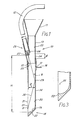
- Figure 1 shows a tool 10 for stone blowing comprising a hopper 11 for stones, a compressed air supply line 12, an upper part 13 of generally tubular cross-section, in this case hollow rectangular section, and a lower part 14 which is generally channel shaped in cross-section.
- the upper end of the lower part 14 is tubular and is dimensioned for mating with the upper part 13 to produce a flush joint 15 inside the tool.
- a key 16 is provided on the lower part for engagement with a slot 17 in the upper part to ensure correct orientation of the two parts.
- the free end 18 of the lower part 14 has an inside surface 19 which is formed as a smooth continuation of the back face 20 of the channel and which is curved through approximately 90°.
- the surface 19 is quarter-circular in cross-section with a centre at point 21.
- the outside surface 22 of the free end 18 is tapered to facilitate the driving of the tool into the ground.
- a port 24 which effects communication between the inside of the tool and the atmosphere.
- a compressed air inlet 26 which is connected to the supply line 12 and which incorporates a nozzle 27.
- Figure 2 shows the tool in use.
- the lower part 14 is detached from the upper part 13 and is driven into a ballast bed 32 alongside a sleeper 33 which has been raised so as to expose a void 34 between the bed and the sleeper.
- the lower part 14 is orientated so that the open front face of the channel faces the sleeper and is driven deep enough so that the void 34 communicates with the channel portion.
- the upper part 13 together with the hopper 11 is then engaged on the lower part.
- the compressed air supply is turned on and the desired quantity of stones are introduced to the hopper 11. The resulting effect is explained below.
- the jet of compressed air through the nozzle causes air to be entrained through the hopper 11 as indicated by arrows 36.
- the entrained air 36 is supplemented by air entrained through the port 24 as indicated by arrow 37 to produce a combined flow of entrained air indicated by arrow 38.
- the velocity of air entrained through the hopper increases in the downward direction because the cross-sectional area of the hopper decreases.
- the stones in the hopper restricted the flow of entrained air through the hopper and thus cause more air to be entrained through the port 24. This ensures that a large mass flow of entrained air is present in the tool 10.
- the jet of air shown as a chain-dotted line 39, causes the entrained air 38 to flow towards the back face 20 of the tool. Due to the low angle of incidence with the back face, the entrained air forms a thin high velocity stream 40 of air along the back face which stream spreads laterally towards and along the side faces 41 (only one shown) of the lower part 14 as the stream flows towards and around the radiussed inside surface 19 of the tool.
- the jet 39 however is reflected along path 30 towards the open mouth of the channel at point X.
- the high velocity stream 40 generally has a large enough mass flow to dislodge the obstructions.
- point X should be made clear concerning the angle of the compressed air inlet and the reflected path 30.
- the position of point X which is determined by the angle of the inlet and the tube dimensions must be located so that in most, if not all, uses of the tool point X is in the exit path of the tool and is not lying against the side face of the sleeper. In the latter case the stones impinged by the reflected jet 30 would hit the sleeper and then drop to the bottom of the tool, i.e. all their kinetic energy in the direction of the void would be lost.
- the point X should not be located on the curved end face 19 of the tool.
- port 24 is such that full entrainment can be achieved through the port if the flow of air through the hopper is reduced to zero.
- the position of the port 24 is such that unless air entrainment through the hopper is reduced or stopped then very little air is entrained through port 24.
- Port 24 therefore acts as a form of 'top-up' facility to ensure that a large mass flow of air is achieved at all times.
- the key 16 is also used to facilitate removal of the lower part 14 from the ballast bed. Furthermore the rigid air supply line 12 is also used as a carrying handle for the upper part of the tool or for the tool as a whole.
- the centre 21 of the part-circular inside surface 19 of the tool is located inwardly of the plane of the open face of the channel and the front end portion 50 of the inside surface 19 is in the form of a lip which is a smooth continuation of said inside surface.
- This lip may be a continuation of the circular arc of the surface 19.
- the lip serves two main purposes, namely to provide a small ramp to aid the propulsion of the stones into the void and to improve the wear characteristics of the tool.
- the tool herein disclosed uses a compressed air supply more efficiently than known tools.
- the present tool can be used continuously with a direct supply of air from a compressor and therefore renders the present system suitable for trackside transport by a small operating gang.
- Other known, less efficient arrangements require such large quantities of compressed air that they cannot be used directly with a compressor alone, but must utilise a large receiver in conjunction with a compressor. Inevitably these known arrangements have to be stopped for considerable periods of time so that the receiver can be charged up by the compressor whereas the present system substantially increases workrate due to it continuous operation.
- the equipment has to be mounted on a railway wagon and it is therefore necessary to have "possession" of the track i.e. the track is effectively closed to all trains.
- the wagon mounted systems also render it very difficult to conduct work on switches and crossings in a railway network.
- the present invention provides a tool for use in stone-blowing comprising a first portion of generally tubular section, a second portion of generally channel section in alignment with and forming a continuation of said first portion, the end of said first portion remote from said second portion constituting an inlet for stones and the free end of said second portion being closed off by a transverse wall shaped externally to facilitate driving the tool into the ground in an upstanding attitude for aligning at least a section of the open front of the second portion with an underground void and shaped internally to deflect laterally through said open front stones moving along the second portion, and a compressed air inlet opening into the first portion at a position below the stone inlet and directed away from the stone inlet so as, in use, to entrain air through the stone inlet, said air inlet incorporating a nozzle.
- the present invention provides a tool for use in stone-blowing comprising a first portion of generally tubular section, a second portion of generally channel section in alignment with and forming a continuation of said first portion, the end of said first portion remote from said second portion constituting an inlet for stones andthe free end of said second portion being closed off by a transverse wall shaped externally to facilitate driving the tool into the ground in an upstanding attitude for aligning at least a section of the open front of the second portion with an underground void and shaped internally to deflect laterally through said open front stones moving along the second portion, and a compressed air inlet opening into the first portion at a position below the stone inlet and directed towards the back face of the channel so that the angle of entry of the compressed air through said air inlet is such that this air rebounds from the back face of the channel and intersects the general plane of the open front of the channel at a point near the free end of the second portion.
- the present invention provides a tool for use in stone-blowing comprising a first portion of generally tubular section, a second portion of generally channel section in alignment with and forming a continuation of said first portion, the end of said first portion remote from said second portion constituting an inlet for stones and the free end of said second portion being closed off by a transverse wall shaped externally to facilitate driving the tool into the ground in an upstanding attitude for aligning at least a section of the open front of the second portion with an underground void and shaped internally to deflect laterally through said open front stones moving along the second portion, and a compressed air inlet opening into the first portion at a position below the stone inlet,said tool being constituted by upper and lower mating parts, in the upper of which is provided the stone inlet and a restriction to constitute a barrier for stopping stones which are larger than a predetermined size.
Landscapes
- Engineering & Computer Science (AREA)
- Architecture (AREA)
- Civil Engineering (AREA)
- Structural Engineering (AREA)
- Machines For Laying And Maintaining Railways (AREA)
- Earth Drilling (AREA)
- Processing Of Stones Or Stones Resemblance Materials (AREA)
- Excavating Of Shafts Or Tunnels (AREA)
Applications Claiming Priority (2)
| Application Number | Priority Date | Filing Date | Title |
|---|---|---|---|
| GB8702354 | 1987-02-03 | ||
| GB878702354A GB8702354D0 (en) | 1987-02-03 | 1987-02-03 | Tool for stone-blowing |
Publications (2)
| Publication Number | Publication Date |
|---|---|
| EP0277802A2 true EP0277802A2 (fr) | 1988-08-10 |
| EP0277802A3 EP0277802A3 (fr) | 1989-06-07 |
Family
ID=10611626
Family Applications (1)
| Application Number | Title | Priority Date | Filing Date |
|---|---|---|---|
| EP88300857A Withdrawn EP0277802A3 (fr) | 1987-02-03 | 1988-02-02 | Outil pour le soufflage de caillasse |
Country Status (4)
| Country | Link |
|---|---|
| US (1) | US4850752A (fr) |
| EP (1) | EP0277802A3 (fr) |
| JP (1) | JPS63197701A (fr) |
| GB (1) | GB8702354D0 (fr) |
Cited By (1)
| Publication number | Priority date | Publication date | Assignee | Title |
|---|---|---|---|---|
| WO2016083700A1 (fr) * | 2014-11-27 | 2016-06-02 | Societe Turripinoise De Mecanique Sa | Outil pour le bourrage de ballast équipé d'un déflecteur |
Families Citing this family (10)
| Publication number | Priority date | Publication date | Assignee | Title |
|---|---|---|---|---|
| US5577446A (en) * | 1995-02-14 | 1996-11-26 | Pandrol Jackson, Inc. | Stoneblower having adjustable workheads and improved blowing tubes |
| US5860763A (en) * | 1996-04-26 | 1999-01-19 | Asplin; Charles Lee | Sidewalk leveling method and device |
| US6334396B2 (en) * | 1999-08-02 | 2002-01-01 | Pandrol Jackson, Inc. | Switch stoneblower |
| US8186907B1 (en) | 2000-10-13 | 2012-05-29 | Charles Lee Asplin | Slab leveling system and method |
| US7226274B1 (en) | 2003-08-26 | 2007-06-05 | Charles Lee Asplin | Cement slab leveling apparatus |
| US6976804B1 (en) | 2003-08-26 | 2005-12-20 | Charles Lee Asplin | Method of repairing damaged concrete slabs |
| US20050058507A1 (en) * | 2003-09-17 | 2005-03-17 | Cedarapids, Inc. | Multi-use paving tractor with tool attachments |
| US10487473B2 (en) | 2017-06-20 | 2019-11-26 | Charles L. Asplin | Wall lifting methods |
| MX2019002582A (es) | 2019-03-05 | 2020-09-07 | Grupo Bimbo Sab De Cv | Sistema automatizado para el manejo de contenedores con carga de producto. |
| CN113494030B (zh) * | 2021-07-27 | 2022-10-14 | 武汉理工大学 | 多通道吹砟装置和方法 |
Family Cites Families (15)
| Publication number | Priority date | Publication date | Assignee | Title |
|---|---|---|---|---|
| US187536A (en) * | 1877-02-20 | Improvement in discharge-nozzles for graiw-eievators | ||
| DE66011C (de) * | E. G. PATTERSON in Titusville, Pennsylvanien, V. St. A | Verfahren zum Höherlegen eingesenkter Schienenträger bezw. Eisenbahnschwellen | ||
| DE419531C (de) * | 1922-11-15 | 1925-10-02 | Kraftbau Patentverwertungs Ges | Vorrichtung zum Spritzen fertig gemischten Moertels |
| US2447216A (en) * | 1947-08-13 | 1948-08-17 | John L Tidwell | Track tool |
| GB689332A (en) * | 1949-10-17 | 1953-03-25 | Frankfurter Maschb Ag | Method of and apparatus for packing up railway sleepers by injection of granular bedding material |
| GB689680A (en) * | 1950-10-18 | 1953-04-01 | George Abdale Alder | Improvements in or relating to the pneumatic conveyance of materials |
| CH309853A (fr) * | 1953-05-20 | 1955-09-30 | Scheuchzer Auguste | Procédé de bourrage des traverses métalliques de chemin de fer et appareillage pour la mise en oeuvre de ce procédé. |
| US2997001A (en) * | 1956-03-03 | 1961-08-22 | Andre Scheuchzer | Method of repairing railway tracks and an installation for carrying out the same |
| US2955880A (en) * | 1957-11-08 | 1960-10-11 | Albers H Michael | Air loader for granular plastic material |
| DE1147553B (de) * | 1959-08-12 | 1963-04-25 | Brieden & Co Maschf K | Im Betriebe verlaengerbares Leitungsstueck zur Druckmittelfoerderung von Bergeversatz |
| GB1380398A (en) * | 1971-06-09 | 1975-01-15 | Sisis Equipment Macclesfield | Apparatus for for'ing drainage trenches |
| GB2021180B (en) * | 1978-05-23 | 1982-07-21 | British Railways Board | Packing raiway sleeper |
| BR8205982A (pt) * | 1981-01-31 | 1983-01-11 | Sendair Int Ltd | Sistema transportador para carregar navios |
| US4370819A (en) * | 1981-03-24 | 1983-02-01 | Ingram Robert E | Apparatus for depositing and spreading ballast |
| SE8406410D0 (sv) * | 1984-12-15 | 1984-12-15 | Rapid Ab Maskin | Transportanordning |
-
1987
- 1987-02-03 GB GB878702354A patent/GB8702354D0/en active Pending
-
1988
- 1988-02-02 EP EP88300857A patent/EP0277802A3/fr not_active Withdrawn
- 1988-02-02 JP JP63022662A patent/JPS63197701A/ja active Pending
- 1988-02-02 US US07/151,503 patent/US4850752A/en not_active Expired - Fee Related
Cited By (2)
| Publication number | Priority date | Publication date | Assignee | Title |
|---|---|---|---|---|
| WO2016083700A1 (fr) * | 2014-11-27 | 2016-06-02 | Societe Turripinoise De Mecanique Sa | Outil pour le bourrage de ballast équipé d'un déflecteur |
| FR3029217A1 (fr) * | 2014-11-27 | 2016-06-03 | Soc Turripinoise De Mec Sa | Outil pour le bourrage de ballast equipe d’un deflecteur |
Also Published As
| Publication number | Publication date |
|---|---|
| EP0277802A3 (fr) | 1989-06-07 |
| JPS63197701A (ja) | 1988-08-16 |
| US4850752A (en) | 1989-07-25 |
| GB8702354D0 (en) | 1987-03-11 |
Similar Documents
| Publication | Publication Date | Title |
|---|---|---|
| US4850752A (en) | Tool for stone-blowing | |
| US4768532A (en) | Underwater pool cleaner | |
| EP0587272B1 (fr) | Dispositif collecteur | |
| TW231974B (en) | Dust sweeping device | |
| KR100655520B1 (ko) | 레일그루브 세척 방법 및 그 장치 | |
| CA2455674A1 (fr) | Systeme a jet d'air pour tete d'imprimante a jet d'encre | |
| CN113499985B (zh) | 一种用于分选物料的喷吹装置及干选机 | |
| US20070066193A1 (en) | Reprofiling device for the rails of railroads that captures waste | |
| GB2202506A (en) | Pneumatic transfer of particulate material | |
| US5372277A (en) | Ball dispensing unit | |
| PL176289B1 (pl) | Ssąca czyszczarka podsypki tłuczniowej toru kolejowego | |
| EP1281593B1 (fr) | Dispositif de sablage pour locomotive | |
| CN117841017B (zh) | 一种整体式机器人 | |
| US5175909A (en) | Suction device | |
| JPH06240605A (ja) | 軌道分岐部の異物除去装置 | |
| JP3846470B2 (ja) | ワークの搬送及び姿勢整理装置 | |
| CN209701498U (zh) | 四向穿梭式货架 | |
| EP0633969B1 (fr) | Tete de giclage | |
| RU2224841C1 (ru) | Снегоуборочная машина | |
| JPH0754317A (ja) | 軌道分岐部の異物除去装置 | |
| JP3674857B2 (ja) | 汚染土壌回収工法とその装置 | |
| CN206928965U (zh) | 重锤式风水联动放炮自动喷雾装置 | |
| KR102287538B1 (ko) | 미세먼지 유입차단 기능이 구비된 스크린도어 | |
| CN120100504B (zh) | 一种掘进机的喷雾降尘系统 | |
| CN119408572B (zh) | 一种重力式撒砂阀 |
Legal Events
| Date | Code | Title | Description |
|---|---|---|---|
| PUAI | Public reference made under article 153(3) epc to a published international application that has entered the european phase |
Free format text: ORIGINAL CODE: 0009012 |
|
| AK | Designated contracting states |
Kind code of ref document: A2 Designated state(s): DE FR GB IT NL |
|
| RAP1 | Party data changed (applicant data changed or rights of an application transferred) |
Owner name: KANGO LIMITED |
|
| PUAL | Search report despatched |
Free format text: ORIGINAL CODE: 0009013 |
|
| AK | Designated contracting states |
Kind code of ref document: A3 Designated state(s): DE FR GB IT NL |
|
| 17P | Request for examination filed |
Effective date: 19891111 |
|
| 17Q | First examination report despatched |
Effective date: 19900903 |
|
| STAA | Information on the status of an ep patent application or granted ep patent |
Free format text: STATUS: THE APPLICATION HAS BEEN WITHDRAWN |
|
| 18W | Application withdrawn |
Withdrawal date: 19911109 |
|
| R18W | Application withdrawn (corrected) |
Effective date: 19911109 |