EP0278021A2 - Dehnungsmessstreifen mit einer dünnen diskontinuierlichen Metallschicht - Google Patents
Dehnungsmessstreifen mit einer dünnen diskontinuierlichen Metallschicht Download PDFInfo
- Publication number
- EP0278021A2 EP0278021A2 EP87101733A EP87101733A EP0278021A2 EP 0278021 A2 EP0278021 A2 EP 0278021A2 EP 87101733 A EP87101733 A EP 87101733A EP 87101733 A EP87101733 A EP 87101733A EP 0278021 A2 EP0278021 A2 EP 0278021A2
- Authority
- EP
- European Patent Office
- Prior art keywords
- metal layer
- thin
- substrate
- strain gauge
- gauge according
- Prior art date
- Legal status (The legal status is an assumption and is not a legal conclusion. Google has not performed a legal analysis and makes no representation as to the accuracy of the status listed.)
- Granted
Links
- 229910052751 metal Inorganic materials 0.000 claims abstract description 45
- 239000002184 metal Substances 0.000 claims abstract description 45
- 239000000758 substrate Substances 0.000 claims abstract description 25
- 238000009792 diffusion process Methods 0.000 claims abstract description 9
- 239000002985 plastic film Substances 0.000 claims abstract description 7
- 229920006255 plastic film Polymers 0.000 claims abstract description 6
- 230000000694 effects Effects 0.000 claims abstract description 5
- 230000003993 interaction Effects 0.000 claims abstract description 3
- PCHJSUWPFVWCPO-UHFFFAOYSA-N gold Chemical group [Au] PCHJSUWPFVWCPO-UHFFFAOYSA-N 0.000 claims description 7
- 229910052737 gold Inorganic materials 0.000 claims description 7
- 239000010931 gold Substances 0.000 claims description 7
- ATJFFYVFTNAWJD-UHFFFAOYSA-N Tin Chemical compound [Sn] ATJFFYVFTNAWJD-UHFFFAOYSA-N 0.000 claims description 5
- 150000002739 metals Chemical class 0.000 claims description 5
- 229910052718 tin Inorganic materials 0.000 claims description 5
- 229910052738 indium Inorganic materials 0.000 claims description 4
- APFVFJFRJDLVQX-UHFFFAOYSA-N indium atom Chemical compound [In] APFVFJFRJDLVQX-UHFFFAOYSA-N 0.000 claims description 4
- BUGBHKTXTAQXES-UHFFFAOYSA-N Selenium Chemical compound [Se] BUGBHKTXTAQXES-UHFFFAOYSA-N 0.000 claims description 3
- HCHKCACWOHOZIP-UHFFFAOYSA-N Zinc Chemical compound [Zn] HCHKCACWOHOZIP-UHFFFAOYSA-N 0.000 claims description 3
- 229910052793 cadmium Inorganic materials 0.000 claims description 3
- BDOSMKKIYDKNTQ-UHFFFAOYSA-N cadmium atom Chemical compound [Cd] BDOSMKKIYDKNTQ-UHFFFAOYSA-N 0.000 claims description 3
- 229920001296 polysiloxane Polymers 0.000 claims description 3
- 229910052711 selenium Inorganic materials 0.000 claims description 3
- 239000011669 selenium Substances 0.000 claims description 3
- 229910052725 zinc Inorganic materials 0.000 claims description 3
- 239000011701 zinc Substances 0.000 claims description 3
- 229910052787 antimony Inorganic materials 0.000 claims description 2
- WATWJIUSRGPENY-UHFFFAOYSA-N antimony atom Chemical compound [Sb] WATWJIUSRGPENY-UHFFFAOYSA-N 0.000 claims description 2
- 229920000642 polymer Polymers 0.000 claims description 2
- XUIMIQQOPSSXEZ-UHFFFAOYSA-N Silicon Chemical compound [Si] XUIMIQQOPSSXEZ-UHFFFAOYSA-N 0.000 abstract description 2
- 229910052710 silicon Inorganic materials 0.000 abstract description 2
- 239000010703 silicon Substances 0.000 abstract description 2
- 229920001887 crystalline plastic Polymers 0.000 abstract 1
- 239000010408 film Substances 0.000 description 13
- -1 polyethylene Polymers 0.000 description 8
- 238000000034 method Methods 0.000 description 7
- 238000005259 measurement Methods 0.000 description 4
- 239000012071 phase Substances 0.000 description 4
- 230000008569 process Effects 0.000 description 4
- 230000035945 sensitivity Effects 0.000 description 4
- 239000004698 Polyethylene Substances 0.000 description 3
- 230000008859 change Effects 0.000 description 3
- 238000004519 manufacturing process Methods 0.000 description 3
- 229920000573 polyethylene Polymers 0.000 description 3
- 238000007740 vapor deposition Methods 0.000 description 3
- 238000001074 Langmuir--Blodgett assembly Methods 0.000 description 2
- KDLHZDBZIXYQEI-UHFFFAOYSA-N Palladium Chemical compound [Pd] KDLHZDBZIXYQEI-UHFFFAOYSA-N 0.000 description 2
- 230000032683 aging Effects 0.000 description 2
- 235000014113 dietary fatty acids Nutrition 0.000 description 2
- 238000009826 distribution Methods 0.000 description 2
- 238000005516 engineering process Methods 0.000 description 2
- 230000008020 evaporation Effects 0.000 description 2
- 238000001704 evaporation Methods 0.000 description 2
- 229930195729 fatty acid Natural products 0.000 description 2
- 239000000194 fatty acid Substances 0.000 description 2
- IPCSVZSSVZVIGE-UHFFFAOYSA-N hexadecanoic acid Chemical class CCCCCCCCCCCCCCCC(O)=O IPCSVZSSVZVIGE-UHFFFAOYSA-N 0.000 description 2
- 239000007787 solid Substances 0.000 description 2
- 229910001220 stainless steel Inorganic materials 0.000 description 2
- 239000010935 stainless steel Substances 0.000 description 2
- 230000001629 suppression Effects 0.000 description 2
- 239000011135 tin Substances 0.000 description 2
- OYPRJOBELJOOCE-UHFFFAOYSA-N Calcium Chemical compound [Ca] OYPRJOBELJOOCE-UHFFFAOYSA-N 0.000 description 1
- 235000021314 Palmitic acid Nutrition 0.000 description 1
- 239000004952 Polyamide Substances 0.000 description 1
- 239000004743 Polypropylene Substances 0.000 description 1
- 239000004793 Polystyrene Substances 0.000 description 1
- BQCADISMDOOEFD-UHFFFAOYSA-N Silver Chemical compound [Ag] BQCADISMDOOEFD-UHFFFAOYSA-N 0.000 description 1
- 206010040925 Skin striae Diseases 0.000 description 1
- 235000021355 Stearic acid Nutrition 0.000 description 1
- 229910000831 Steel Inorganic materials 0.000 description 1
- 208000031439 Striae Distensae Diseases 0.000 description 1
- 239000000853 adhesive Substances 0.000 description 1
- 230000001070 adhesive effect Effects 0.000 description 1
- QVGXLLKOCUKJST-UHFFFAOYSA-N atomic oxygen Chemical compound [O] QVGXLLKOCUKJST-UHFFFAOYSA-N 0.000 description 1
- 229910052788 barium Inorganic materials 0.000 description 1
- DSAJWYNOEDNPEQ-UHFFFAOYSA-N barium atom Chemical compound [Ba] DSAJWYNOEDNPEQ-UHFFFAOYSA-N 0.000 description 1
- 230000004888 barrier function Effects 0.000 description 1
- 229910052791 calcium Inorganic materials 0.000 description 1
- 239000011575 calcium Substances 0.000 description 1
- 239000004020 conductor Substances 0.000 description 1
- 230000008878 coupling Effects 0.000 description 1
- 238000010168 coupling process Methods 0.000 description 1
- 238000005859 coupling reaction Methods 0.000 description 1
- 238000000354 decomposition reaction Methods 0.000 description 1
- 238000000151 deposition Methods 0.000 description 1
- 230000008021 deposition Effects 0.000 description 1
- 238000001514 detection method Methods 0.000 description 1
- 239000003989 dielectric material Substances 0.000 description 1
- 238000010292 electrical insulation Methods 0.000 description 1
- 238000005566 electron beam evaporation Methods 0.000 description 1
- 229920006332 epoxy adhesive Polymers 0.000 description 1
- 230000002349 favourable effect Effects 0.000 description 1
- 239000011888 foil Substances 0.000 description 1
- 239000007789 gas Substances 0.000 description 1
- 239000011521 glass Substances 0.000 description 1
- 239000007791 liquid phase Substances 0.000 description 1
- 159000000003 magnesium salts Chemical class 0.000 description 1
- 230000035800 maturation Effects 0.000 description 1
- 230000007246 mechanism Effects 0.000 description 1
- 230000008018 melting Effects 0.000 description 1
- 238000002844 melting Methods 0.000 description 1
- 238000001465 metallisation Methods 0.000 description 1
- WQEPLUUGTLDZJY-UHFFFAOYSA-N n-Pentadecanoic acid Chemical class CCCCCCCCCCCCCCC(O)=O WQEPLUUGTLDZJY-UHFFFAOYSA-N 0.000 description 1
- 229910000510 noble metal Inorganic materials 0.000 description 1
- QIQXTHQIDYTFRH-UHFFFAOYSA-N octadecanoic acid Chemical class CCCCCCCCCCCCCCCCCC(O)=O QIQXTHQIDYTFRH-UHFFFAOYSA-N 0.000 description 1
- OQCDKBAXFALNLD-UHFFFAOYSA-N octadecanoic acid Natural products CCCCCCCC(C)CCCCCCCCC(O)=O OQCDKBAXFALNLD-UHFFFAOYSA-N 0.000 description 1
- 150000002902 organometallic compounds Chemical class 0.000 description 1
- 229910052760 oxygen Inorganic materials 0.000 description 1
- 239000001301 oxygen Substances 0.000 description 1
- 229910052763 palladium Inorganic materials 0.000 description 1
- 239000012188 paraffin wax Substances 0.000 description 1
- 230000000704 physical effect Effects 0.000 description 1
- 238000005240 physical vapour deposition Methods 0.000 description 1
- 239000004033 plastic Substances 0.000 description 1
- 229920003023 plastic Polymers 0.000 description 1
- 229920002647 polyamide Polymers 0.000 description 1
- 229920000015 polydiacetylene Polymers 0.000 description 1
- 229920000139 polyethylene terephthalate Polymers 0.000 description 1
- 229920001155 polypropylene Polymers 0.000 description 1
- 229920002223 polystyrene Polymers 0.000 description 1
- 229920002635 polyurethane Polymers 0.000 description 1
- 239000004814 polyurethane Substances 0.000 description 1
- 239000010453 quartz Substances 0.000 description 1
- 230000005855 radiation Effects 0.000 description 1
- 239000011435 rock Substances 0.000 description 1
- 150000003839 salts Chemical class 0.000 description 1
- VYPSYNLAJGMNEJ-UHFFFAOYSA-N silicon dioxide Inorganic materials O=[Si]=O VYPSYNLAJGMNEJ-UHFFFAOYSA-N 0.000 description 1
- 229910052709 silver Inorganic materials 0.000 description 1
- 239000004332 silver Substances 0.000 description 1
- 238000001179 sorption measurement Methods 0.000 description 1
- 238000004544 sputter deposition Methods 0.000 description 1
- 230000003068 static effect Effects 0.000 description 1
- 239000008117 stearic acid Substances 0.000 description 1
- 239000010959 steel Substances 0.000 description 1
- 230000035882 stress Effects 0.000 description 1
- 239000000126 substance Substances 0.000 description 1
- 230000002123 temporal effect Effects 0.000 description 1
- 238000002207 thermal evaporation Methods 0.000 description 1
- 239000010409 thin film Substances 0.000 description 1
- 230000007704 transition Effects 0.000 description 1
Images

Classifications
-
- G—PHYSICS
- G01—MEASURING; TESTING
- G01B—MEASURING LENGTH, THICKNESS OR SIMILAR LINEAR DIMENSIONS; MEASURING ANGLES; MEASURING AREAS; MEASURING IRREGULARITIES OF SURFACES OR CONTOURS
- G01B7/00—Measuring arrangements characterised by the use of electric or magnetic techniques
- G01B7/16—Measuring arrangements characterised by the use of electric or magnetic techniques for measuring the deformation in a solid, e.g. by resistance strain gauge
- G01B7/18—Measuring arrangements characterised by the use of electric or magnetic techniques for measuring the deformation in a solid, e.g. by resistance strain gauge using change in resistance
-
- G—PHYSICS
- G01—MEASURING; TESTING
- G01L—MEASURING FORCE, STRESS, TORQUE, WORK, MECHANICAL POWER, MECHANICAL EFFICIENCY, OR FLUID PRESSURE
- G01L1/00—Measuring force or stress, in general
- G01L1/20—Measuring force or stress, in general by measuring variations in ohmic resistance of solid materials or of electrically-conductive fluids; by making use of electrokinetic cells, i.e. liquid-containing cells wherein an electrical potential is produced or varied upon the application of stress
- G01L1/22—Measuring force or stress, in general by measuring variations in ohmic resistance of solid materials or of electrically-conductive fluids; by making use of electrokinetic cells, i.e. liquid-containing cells wherein an electrical potential is produced or varied upon the application of stress using resistance strain gauges
- G01L1/2287—Measuring force or stress, in general by measuring variations in ohmic resistance of solid materials or of electrically-conductive fluids; by making use of electrokinetic cells, i.e. liquid-containing cells wherein an electrical potential is produced or varied upon the application of stress using resistance strain gauges constructional details of the strain gauges
-
- H—ELECTRICITY
- H01—ELECTRIC ELEMENTS
- H01C—RESISTORS
- H01C10/00—Adjustable resistors
- H01C10/10—Adjustable resistors adjustable by mechanical pressure or force
Definitions
- the invention relates to highly sensitive strain gauges with a thin discontinuous metal layer which changes its resistance when stretched and has improved stability.
- Strain gauges as sensors for strain gauges, which are based on the physical effect that an electrical conductor has its resistance under mechanical stress, e.g. Elongation changes have been known for a long time and serve e.g. the detection of expansion of components due to static or dynamic loads.
- Elongation changes have been known for a long time and serve e.g. the detection of expansion of components due to static or dynamic loads.
- a wire laid in turns is generally embedded in plastic and is firmly connected to the object to be examined. Due to the linear coupling of strain and change in resistance, strains ⁇ of less than 10 ⁇ 6 can no longer be resolved.
- the state of the art is e.g. to US-A 2 556 132 and 2 621 276 and the monograph "Strain Gauge Technology" by A.L. Window and G.S. Holister, Applied Science Publishers Ltd., Essex, England, 1982. Strain gauges show a higher sensitivity, but the disadvantage of a strong temperature dependence.
- strains ⁇ of less than 10 ist is important.
- the present invention has for its object to find highly sensitive strain gauges that are sufficiently stable over time for measurement purposes in technology.
- strain gauges in which the thin discontinuous metal layer is applied uniformly to a substrate which, through interaction with the metal during and / or after the application, diffuses in and thus the above Structural instability of the discontinuous metal layer described greatly reduced by shifting the distances between the metal islands.
- the invention thus relates to strain gauges of the type specified in the claims.
- the thin, discontinuous metal layers used according to the invention for the strain gauges are the thinnest layers of island-forming metals such as gold, tin, zinc, indium, cadmium, antimony or selenium, as can be seen in particular in a discontinuous layer by vapor deposition above their melting point in a high vacuum get applied.
- the size of the metal clusters is generally not more than 200 ⁇ and preferably about 30 to 50 ⁇ .
- the average thickness of the discontinuous metal layers applied is generally 30 to 500 ⁇ and in particular 50 to 200 ⁇ and depends not only on the metal used but also on the resistance value of the metal layer, which is favorable for the specific purpose and whose conduction mechanism is based primarily on the tunnel effect (tunnel current ).
- metal layer such as cathode sputtering, electron beam evaporation or decomposition of an organometallic compound on the substrate, e.g. on a heated substrate.
- Electrolytic methods of metal deposition can also be considered.
- lead electrodes can also be applied, but these are often only applied later before use.
- strain gauges according to the invention and their manufacture are the application to substrates which, by interacting with the metal of the metal layer, greatly reduce the possible diffusion of the metals of the layer. This can be done by increasing the diffusion barriers or by creating a shielding film on the metallic phase. It has been shown that the use of substrates with ordered structures, oriented or crystalline structural areas results in an orientation in the deposited metal layer, which greatly reduces their diffusion processes and increases their structural stability.
- tin, indium, zinc and cadmium are deposited epitaxially during vapor deposition in a high vacuum and the resulting discontinuous Metal layers show greatly reduced diffusion processes and the desired structural stability.
- the evaporation of tin and indium is similar for uniaxially oriented films made of isotactic polystyrene.
- the densest packed crystallographic directions run parallel to the chain direction.
- the oriented substrate films have a thickness of in particular from 25 to 1000 and preferably from 200 to 500 ⁇ .
- the application of the metal layers to polymers with crystalline components leads e.g. Semi-crystalline polydiacetylenes, polyethylene terephthalates or polyamides to interact with the metal layers and reduce the diffusion processes in them.
- Gas phase deposition PVD, CVD
- PVD vacuum phase deposition
- the ultra-thin films made with the Langmuir-Blodgett technique can e.g. be produced from salts, in particular barium, calcium or magnesium salts of stearic acid or palmitic acid or from diacetylene fatty acids.
- Such films e.g. from diacetylene fatty acids, in addition to increasing their lateral stability, they can also be polymerized or crosslinked by radiation.
- the vapor deposition techniques allow an imagewise structuring of the substrates or the applied active metal layers. This allows special patterns to be created depending on the measurement problem.
- the microscopic expansion of the conductive areas and the insulating intermediate areas allows very small sensors to be produced in comparison to classic strain gauges ( ⁇ 1 mm2). If necessary, a grid made of such strain-sensitive sensors can be used to image tear distributions on solid surfaces. Brittle substrate films adhering well to the surface are preferably used for this purpose, which transfer low strains to the discontinuous metal layer.
- coated plastic films and in particular silicone-coated plastic films such as polyethylene films have also proven useful as thin substrates, the silicone layer preferably being less than 10 ⁇ m and the substrate preferably being less than 100 ⁇ m thick.
- the silicone layer preferably being less than 10 ⁇ m and the substrate preferably being less than 100 ⁇ m thick.
- the substrates are not applied directly to the specimen, they should be dimensionally stable (e.g. brittle) and be able to transfer even very small strains from the specimen to the discontinuous metal layer.
- Sufficient adhesion to the test specimens which is also advantageous with adhesives, e.g. Epoxy adhesive or polyurethane, or can be made with tape.
- the discontinuous metal layers it is very expedient to apply a thin top layer over the metal layer, e.g. evaporate, e.g. SiO layers or paraffin layers, which also act as protection against chemical influences, e.g. can serve through oxygen or moisture.
- a thin top layer over the metal layer, e.g. evaporate, e.g. SiO layers or paraffin layers, which also act as protection against chemical influences, e.g. can serve through oxygen or moisture.
- the structural instability of the discontinuous metal layer of the strain gauge can often also be improved by such a cover layer.
- the strain gauges according to the invention are distinguished by a high sensitivity, which is more than an order of magnitude above that of conventional strain gauges. After an initial aging period, they also have good temporal stability with regard to the increase in resistance of the strain gauges. Compared to conventional measuring strips, the measuring length can be reduced to 1 mm and below. They are not only easy to manufacture, but just as easy to provide with lead electrodes in a known manner and to measure with known resistance measuring devices.
- the tunnel stretch marks were made by thermal evaporation of gold in a vacuum of 10 ⁇ 4 Pa.
- the substrate was a silicon-coated high-pressure polyethylene film on which a discontinuous gold film with an average thickness of 13 nm was applied.
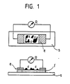
- the carrier substrate was provided with lead electrodes of about 2 ⁇ m thick, between which a 0.5 ⁇ 6 mm wide strip was produced using a mask. After removing the mask, the actual sensor was created in this strip, the resistance of the sensor being continuously monitored during the measurement. With a total resistance of 8 M ⁇ , the evaporation was ended and the finished measuring strip on the cleaned surface of a noble steel rod glued (Fig. 1). The distance between the electrodes is 0.5 mm, the width of the film 6 mm.
- f represents the substrate, d the evaporated gold film, e the lead electrodes, s the stainless steel substrate to be examined and R the resistance measuring device.
- the strains were varied between 10 ⁇ 6 and 2 ⁇ 10 ⁇ 5.
- Fig. 2 shows the change in resistance ⁇ R (k ⁇ ) of the measuring strip as a function of the duration of the various loads, the sharp peaks that occur in the loaded states ⁇ 1 and ⁇ 4 caused by vibrations when lifting the loads.
- ⁇ R / R ⁇ 10 ⁇ 4 versus ⁇ ⁇ 10 ⁇ 6
- a linear change in resistance results in the strain range.
- the surface resistance of the strain gauge changes reversibly in the temperature range between 253 and 293 K.
- the "aging process”, i.e. the gradual changes in the resistance of the measuring strips produced in this way are completed within a few days under normal ambient conditions.
Landscapes
- Physics & Mathematics (AREA)
- General Physics & Mathematics (AREA)
- Engineering & Computer Science (AREA)
- Microelectronics & Electronic Packaging (AREA)
- Measurement Of Length, Angles, Or The Like Using Electric Or Magnetic Means (AREA)
Abstract
Description
- Die Erfindung betrifft hochempfindliche Dehnungsmeßstreifen mit einer dünnen diskontinuierlichen Metallschicht, die ihren Widerstand bei Dehnung ändert und eine verbesserte Stabilität aufweist.
- Dehnungsmeßstreifen als Meßwertgeber für Dehnungsmesser, denen der physikalische Effekt zugrundeliegt, daß ein elektrischer Leiter seinen Widerstand bei mechanischer Beanspruchung, z.B. Dehnung ändert, sind lange Zeit bekannt und dienen z.B. der Erfassung von Dehnungen von Bauteilen durch statische oder dynamische Belastungen. Bei konventionellen Draht- bzw. Folien-Dehnungsmeßstreifen ist im allgemeinen ein in Windungen gelegter Draht in Kunststoff eingebettet und wird fest mit dem zu untersuchenden Objekt verbunden. Durch die lineare Kopplung von Dehnung und Widerstandsänderung können Dehnungen ε von unter 10⁻⁶ nicht mehr aufgelöst werden. Zum Stand der Technik sei z.B. auf die US-A 2 556 132 und 2 621 276 sowie die Monographie "Strain Gauge Technology" von A.L. Window and G.S. Holister, Applied Science Publishers Ltd., Essex, England, 1982, verwiesen. Halbleiterdehnungsmeßstreifen zeigen eine höhere Empflindlichkeit, jedoch den Nachteil einer starken Temperaturabhängigkeit.
- In manchen Gebieten wie bei der Erforschung von Kriechvorgängen, der unelastischen Deformation, Phasenübergängen, geologischen Deformationsvorgängen in Fels oder Eis bis etc. ist jedoch die Messung von Dehnungen ε von kleiner als 10⁻⁶ bedeutsam.
- Untersuchungen über diskontinuierliche Metallschichten auf Dielektrika wie Schichten von Gold, Silber, Palladium oder Zinn auf Glas oder Quarzsubstraten sind bekannt (vgl. Advances in Physics 24, 407-461 (1975); J.Appl. Physics, Vol.34, 2700-2708 (1963)). Nachteilig bei den untersuchten Systemen ist ihre strukturelle Instabilität aufgrund von diffusionskontrollierten Reifungsvorgängen in den diskontinuierlichen Metallschichten, die zu einer Verschiebung der Abstandsverteilung zwischen den metallischen Inseln der Schicht zu größeren Abständen hinführt. Dies führt zu einem schnellen Ansteigen des elektrischen Widerstandes der untersuchten diskontinuierlichen Metallschichten und letztlich zur Unterdrückung der Tunnelströme in der diskontinuierlichen Metallschicht und zur elektrischen Isolation.
- Der vorliegenden Erfindung liegt die Aufgabe zugrunde, hochempfindliche Dehnungsmeßstreifen zu finden, die für Meßzwecke der Technik hinreichend zeitlich stabil sind.
- Es wurde nun gefunden, daß die Aufgabe gelöst werden kann mit der Herstellung von Dehnungsmeßstreifen, bei denen die dünne diskontinuierliche Metallschicht gleichmäßig auf ein Substrat aufgebracht wird, das durch Wechselwirkung mit dem Metall beim und/oder nach dem Aufbringen die Diffusionen in und somit die oben beschriebene strukturelle Instabilität der diskontinuierlichen Metallschicht durch Verschiebung der Abstände der Metallinseln stark herabsetzt.
- Gegenstand der Erfindung sind somit Dehnungsmeßstreifen der in den Ansprüchen angegebenen Art.
- Bei den erfindungsgemäß für die Dehnungsmeßstreifen verwandten dünnen, diskontinuierlichen Metallschichten handelt es sich um dünnste Schichten von inselbildenden Metallen wie Gold, Zinn, Zink, Indium, Cadmium, Antimon oder Selen, wie sie sich insbesondere durch Aufdampfen oberhalb ihres Schmelzpunktes im Hochvakuum gleichmäßig in diskontinuierlicher Schicht aufbringen lassen. Die Größe der Metallcluster beträgt dabei im allgemeinen nicht mehr als 200 Å und bevorzugt ca. 30 bis 50 Å. Die durchschnittliche Dicke der aufgebrachten diskontinuierlichen Metallschichten liegt im allgemeinen bei 30 bis 500 Å und insbesondere bei 50 bis 200 Å und richtet sich außer nach dem verwendeten Metall nach dem für den speziellen Verwendungszweck günstigen Widerstandswert der Metallschicht, deren Leitungsmechanismus vorwiegend auf dem Tunneleffekt beruht (Tunnelstrom). Zum Aufbringen der Metallschicht sind auch andere bekannte Verfahren geeignet wie die Kathodenzerstäubung, Elektronenstrahlverdampfung oder eine Zersetzung einer metallorganischen Verbindung auf dem Substrat, z.B. auf einem erhitzten Substrat. Auch elektrolytische Verfahren der Metallabscheidung können in Betracht kommen. Im gleichen Arbeitsgang wie das Aufbringen der Metallschicht können auch Ableitelektroden aufgebracht werden, die aber oft erst später vor der Anwendung aufgebracht werden.
- Ein wesentliches Kennzeichen der erfindungsgemäßen Dehnungsmeßstreifen und ihrer Herstellung ist das Aufbringen auf Substrate, die durch Wechselwirkung mit dem Metall der Metallschicht die mögliche Diffusion der Metalle der Schicht stark herabsetzen. Dies kann durch Erhöhung der Diffusionsbarrieren oder aber auch durch Erzeugen eines abschirmenden Films auf der metallischen Phase erfolgen. So hat sich gezeigt, daß durch die Verwendung von Substraten mit geordneten Strukturen, orientierten bzw. kristallinen Strukturbereichen eine Orientierung in der abgeschiedenen Metallschicht erfolgt, die ihre Diffusionsprozesse stark herabsetzt und ihre strukturelle Stabilität erhöht. So werden bei Verwendung dünner uniaxial orientierter Kunststoffilme wie Polyethylen-, Polypropylen- oder Polybutylen-1-Filme Zinn, Indium, Zink und Cadmium epitaktisch bei Aufdampfen im Hochvakuum abgeschieden und die resultierenden diskontinuier lichen Metallschichten zeigen stark herabgesetzte Diffusionsprozesse und die gewünschte strukturelle Stabilität. Ähnlich verläuft das Aufdampfen von Zinn und Indium bei uniaxial orientierten Filmen aus isotaktischen Polystyrol. Die dichtest gepackten kristallographischen Richtungen verlaufen dabei parallel zur Kettenrichtung. Die orientierten Substratfilme haben insbesondere eine Stärke von 25 bis 1000 und bevorzugt von 200 bis 500 Å.
- Ähnlich führt das Aufbringen der Metallschichten auf Polymere mit kristallinen Anteilen z.B. teilkristalline Polydiacetylene, Polyethylenterephthalate oder Polyamide zu einer Wechselwirkung mit den Metallschichten und herabgesetzten Diffusionsprozessen in ihnen. Ähnliches gilt für geordnete ultradünne Schichten einer Schichtstärke von unter 0,1 µm als Substrate, die vorteilhaft mit der Langmuir-Blodgett-Technik (vgl. Thin Solid Films Vol. 99, Seiten 1-328 (1983)) oder auch durch Flüssigphasenadsorption direkt auf die zu messenden Probekörper, z.B. Werkstücke, aufgebracht werden können. In Betracht kommen hier auch die Gasphasenabscheidung (PVD, CVD). Die mit der Langmuir-Blodgett-Technik hergestellten ultradünnen Filme können z.B. aus Salzen, insbesondere Barium-, Calcium-oder Magnesiumsalzen der Stearinsäure oder Palmitinsäure oder aus Diacetylenfettsäuren hergestellt sein. Solche Filme, z.B. aus Diacetylenfettsäuren, können zusätzlich zur Erhöhung ihrer lateralen Stabilität auch durch Strahlung polymerisiert oder vernetzt sein.
- Die Aufdampftechniken gestatten eine bildmäßige Strukturierung der Substrate bzw. der aufgebrachten aktiven Metallschichten. Damit lassen sich spezielle Muster in Abhängigkeit vom Meßproblem erzeugen.
- Darüber hinaus gestattet es die mikroskopische Ausdehnung der leitenden Bereiche und der isolierenden Zwischenbereiche im Vergleich zu klassischen Dehnungsmeßstreifen sehr kleine Sensoren herzustellen (< 1 mm²). Gegebenenfalls kann ein Gitter aus solchen dehnungsempfindlichen Sensoren zur Abbildung von Reißverteilungen auf Festkörperoberflächen herangezogen werden. Vorzugsweise werden hierzu gut an der Oberfläche haftende spröde Substratfilme eingesetzt, die geringe Dehnungen auf die diskontinuierliche Metallschicht übertragen.
- Für diskontinuierliche Schichten von inerten Metallen, insbesondere Edelmetallen und bevorzugt von Gold, haben sich als dünne Substrate auch beschichtete Kunststoffilme und inbesondere silikonbeschichtete Kunststoffilme wie Polyethylenfilme bewährt, wobei die Silikonschicht bevorzugt kleiner als 10 µm und das Substrat bevorzugt kleiner als 100 µm dick ist. Hier wird wohl durch Erzeugung eines abschirmenden Filmes auf der metallischen Phase eine starke Unterdrückung der Diffusion in der diskontinuierlichen Metallschicht erzielt.
- Soweit die Substrate nicht direkt auf die Probenkörper aufgebracht werden, sollen sie dimensionsstabil (z.B. spröde) und in der Lage sein, auch sehr geringe Dehnungen vom Probenkörper auf die diskontinuierliche Metallschicht zu übertragen. Von Vorteil ist eine hinreichende Haftung gegenüber den Probenkörpern, die auch mit Klebstoffen, z.B. Epoxidkleber oder Polyurethanen, oder mit Klebeband hergestellt werden kann.
- In manchen Fällen, z.B. bei bestimmten Metallen, z.B. Selen, in den diskontinuierlichen Metallschichten, ist es sehr zweckmäßig, über die Metallschicht noch eine dünne Deckschicht aufzubringen, z.B. aufzudampfen, z.B. SiO-Schichten oder Paraffinschichten, die auch als Schutz gegen chemische Einflüsse, z.B. durch Sauerstoff oder Feuchtigkeit dienen können. Oft kann auch durch eine solche Deckschicht die strukturelle Instabilität der diskontinuierlichen Metallschicht des Dehnungsmeßstreifens noch verbessert werden.
- Die erfindungsgemäßen Dehnungsmeßstreifen zeichnen sich durch eine hohe Empfindlichkeit, die mehr als eine Größenordnung über der konventioneller Dehnungsmeßstreifen liegt, aus. Sie weisen zudem nach einer anfänglichen Alterungsperiode bezüglich des Widerstandanstiegs der Dehnungsmeßstreifen eine gute zeitliche Stabilität auf. Gegenüber konventioneller Meßstreifen kann die Meßlänge auf 1 mm und darunter verkleinert werden. Sie sind nicht nur einfach herzustellen, sondern ebenso einfach in bekannter Art mit Ableitelektroden zu versehen und mit bekannten Widerstandsmeßgeräten zu messen.
- Das nachstehende Beispiel soll die Erfindung weiter erläutern.
- Die Tunnel-Dehnungsstreifen wurden durch thermisches Verdampfen von Gold in einem Vakuum von 10⁻⁴ Pa hergestellt. Substrat war eine siliconbeschichtete Hochdruckpolyethylen-Folie, auf die ein diskontinuierlicher Goldfilm mit einer mittleren Dicke von 13 nm aufgebracht wurde. Das Trägersubstrat wurde in einem ersten Arbeitsgang mit etwa 2 µm dicken Ableitelektroden versehen, zwischen denen mit Hilfe einer Maske ein 0,5 × 6 mm breiter Streifen erzeugt wurde. Nach Entfernen der Maske wurde der eigentliche Sensor in diesem Streifen erzeugt, wobei während der Messung der Widerstand des Sensors kontinuierlich überwacht wurde. Bei einem Gesamtwiderstand von 8 MΩ wurde die Bedampfung beendet und der fertiggestellte Meßstreifen auf die gereinigte Oberfläche eines Edel stahlstabes geklebt (Fig. 1). Der Abstand der Elektroden beträgt 0,5 mm, die Breite des Films 6 mm. In Fig. 1 stellt f das Substrat, d den aufgedampften Goldfilm, e die Ableitelektroden, s das zu untersuchende Edelstahlsubstrat und R das Widerstandsmeßgerät dar.
- Der Edelstahlstab mit dem aufgeklebten Dehnungsmeßstreifen wurde in eine Vierpunktdehneinrichtung eingebaut, und es wurden die relativen Widerstandsänderungen Δ R/R bei verschiedenen Dehnungen (ε = Δl/l) bestimmt. Dabei wurden die Dehnungen zwischen 10⁻⁶ und 2 · 10⁻⁵ variiert. Fig. 2 gibt die Widerstandsänderung ΔR (kΩ) des Meßstreifens in Abhängigkeit der Zeitdauer der verschiedenen Belastungen wieder, wobei die scharfen Spitzen, die in den belasteten Zuständen ε₁ und ε₄ auftreten, durch Vibrationen beim Abheben der Lasten verursacht wurden. Die aufgeprägten Dehnungen betrugen: ε₀ = 0, ε₁ = 20,068 · 10⁻⁶, ε₂ = 10,084 · 10⁻⁶, ε₃ = 5.017 · 10⁻⁶, ε₄ = 2.068 · 10⁻⁶, ε₅ = 1.035 · 10⁻⁶. Beim Auftragen der Werte ΔR/R · 10⁻⁴ gegen ε · 10⁻⁶ als Widerstands-Dehnungs-Charakteristik ergibt sich im Dehnungsbereich eine lineare Änderung des Widerstands. Die Empfindlichkeit k = (ΔR/R)/(Δl/l) des Meßstreifens ergibt k = 125 ± 10, verglichen mit einer Empfindlichkeit k = 2 bei konventionellen Dehnungsmeßstreifen.
- Der Flächenwiderstand des Dehnungsmeßstreifens ändert sich reversibel im Temperaturbereich zwischen 253 und 293 K. Der "Alterungsprozeß", d.h. die allmählichen Veränderungen im Widerstand der so hergestellten Meßstreifen ist bei normalen Umgebungsbedingungen innerhalb weniger Tage abgeschlossen.
Claims (8)
Priority Applications (1)
| Application Number | Priority Date | Filing Date | Title |
|---|---|---|---|
| DE8787101733T DE3769305D1 (de) | 1987-02-09 | 1987-02-09 | Dehnungsmessstreifen mit einer duennen diskontinuierlichen metallschicht. |
Applications Claiming Priority (1)
| Application Number | Priority Date | Filing Date | Title |
|---|---|---|---|
| DE19863603449 DE3603449A1 (de) | 1986-02-05 | 1986-02-05 | Dehnungsmessstreifen mit einer duennen diskontinuierlichen metallschicht |
Publications (3)
| Publication Number | Publication Date |
|---|---|
| EP0278021A2 true EP0278021A2 (de) | 1988-08-17 |
| EP0278021A3 EP0278021A3 (en) | 1988-10-05 |
| EP0278021B1 EP0278021B1 (de) | 1991-04-10 |
Family
ID=6293375
Family Applications (1)
| Application Number | Title | Priority Date | Filing Date |
|---|---|---|---|
| EP87101733A Expired - Lifetime EP0278021B1 (de) | 1986-02-05 | 1987-02-09 | Dehnungsmessstreifen mit einer dünnen diskontinuierlichen Metallschicht |
Country Status (4)
| Country | Link |
|---|---|
| US (1) | US4812800A (de) |
| EP (1) | EP0278021B1 (de) |
| JP (1) | JPS62185102A (de) |
| DE (1) | DE3603449A1 (de) |
Cited By (1)
| Publication number | Priority date | Publication date | Assignee | Title |
|---|---|---|---|---|
| DE4408043A1 (de) * | 1994-03-10 | 1995-09-28 | Hochtief Ag Hoch Tiefbauten | Vorrichtung zum Überwachen der Spannkraft eines Spannelementes |
Families Citing this family (10)
| Publication number | Priority date | Publication date | Assignee | Title |
|---|---|---|---|---|
| US5134248A (en) * | 1990-08-15 | 1992-07-28 | Advanced Temperature Devices, Inc. | Thin film flexible electrical connector |
| US5679888A (en) * | 1994-10-05 | 1997-10-21 | Matsushita Electric Industrial Co., Ltd. | Dynamic quantity sensor and method for producing the same, distortion resistance element and method for producing the same, and angular velocity sensor |
| KR0174872B1 (ko) * | 1995-12-08 | 1999-02-01 | 양승택 | 압 저항 소자 및 그의 제조방법 |
| EP0881691B1 (de) * | 1997-05-30 | 2004-09-01 | Matsushita Electric Industrial Co., Ltd. | Anordnung mit Quanten-Schachteln |
| AUPR725601A0 (en) * | 2001-08-24 | 2001-09-20 | Commonwealth Scientific And Industrial Research Organisation | Strain gauges |
| JP4150013B2 (ja) * | 2005-03-31 | 2008-09-17 | Tdk株式会社 | トンネル効果素子 |
| DE102006004922B4 (de) * | 2006-02-01 | 2008-04-30 | Nanoscale Systems Nanoss Gmbh | Miniaturisiertes Federelement und Verfahren zu dessen Herstellung, Balkensonde, Rasterkraftmikroskop sowie Verfahren zu dessen Betrieb |
| US9121258B2 (en) | 2010-11-08 | 2015-09-01 | Baker Hughes Incorporated | Sensor on a drilling apparatus |
| US9057247B2 (en) * | 2012-02-21 | 2015-06-16 | Baker Hughes Incorporated | Measurement of downhole component stress and surface conditions |
| WO2019195618A1 (en) * | 2018-04-04 | 2019-10-10 | The Regents Of The University Of California | Non-contact measurements of fluids, particles and bubbles |
Family Cites Families (3)
| Publication number | Priority date | Publication date | Assignee | Title |
|---|---|---|---|---|
| US2556132A (en) * | 1948-10-28 | 1951-06-05 | Chrysler Corp | Strain gauge |
| US2621276A (en) * | 1949-12-09 | 1952-12-09 | Lockheed Aircraft Corp | Electrical strain gauge and method of making same |
| DE2916425C2 (de) * | 1979-04-23 | 1981-04-09 | Siemens AG, 1000 Berlin und 8000 München | Dehnungsmeßstreifen und Verfahren zu seiner Herstellung |
-
1986
- 1986-02-05 DE DE19863603449 patent/DE3603449A1/de not_active Withdrawn
-
1987
- 1987-01-23 JP JP62012626A patent/JPS62185102A/ja active Pending
- 1987-02-05 US US07/010,995 patent/US4812800A/en not_active Expired - Fee Related
- 1987-02-09 EP EP87101733A patent/EP0278021B1/de not_active Expired - Lifetime
Cited By (1)
| Publication number | Priority date | Publication date | Assignee | Title |
|---|---|---|---|---|
| DE4408043A1 (de) * | 1994-03-10 | 1995-09-28 | Hochtief Ag Hoch Tiefbauten | Vorrichtung zum Überwachen der Spannkraft eines Spannelementes |
Also Published As
| Publication number | Publication date |
|---|---|
| JPS62185102A (ja) | 1987-08-13 |
| EP0278021B1 (de) | 1991-04-10 |
| DE3603449A1 (de) | 1987-08-06 |
| EP0278021A3 (en) | 1988-10-05 |
| US4812800A (en) | 1989-03-14 |
Similar Documents
| Publication | Publication Date | Title |
|---|---|---|
| EP1535035B1 (de) | Feuchtigkeitsschutz für einen elektromechanischen wandler | |
| EP0280089B1 (de) | Verfahren zum Herstellen einer als Kontakt- und Barriereschicht wirkenden Titan/Titannitrid-Doppelschicht in höchstintegrierten Schaltungen | |
| EP0087419B1 (de) | Dünnschicht-dehnungsmessstreifen und verfahren zu seiner herstellung | |
| EP0278021B1 (de) | Dehnungsmessstreifen mit einer dünnen diskontinuierlichen Metallschicht | |
| EP0010771B1 (de) | Kapazitiver Feuchtefühler | |
| EP0019135A2 (de) | Messonde zur Verwendung bei der Messung der Temperatur oder Masse eines strömenden Mediums und Verfahren zu ihrer Herstellung | |
| EP0226572B1 (de) | Messwertaufnehmer mit einem flexiblen piezoelektrischen Film als Messelement | |
| DE3025996C2 (de) | Verfahren zur Herstellung eines Wegaufnehmers | |
| DE3032476A1 (de) | Selektiver duennschicht-gassensor hoher empfindlichkeit und stabilitaet zum nachweis und zur messung von gasfoermigen kohlenwasserstoff-verunreinigungen in der luft auf der basis von wolframoxid (wo(pfeil abwaerts)x(pfeil abwaerts))-halbleitern, sowie ein verfahren zu seiner herstellung | |
| EP0191785A1 (de) | Verfahren zum herstellen einer messonde zur verwendung bei der messung der temperatur oder masse eines strömenden mediums | |
| EP1345019B1 (de) | Temperatursensor | |
| EP0017982B1 (de) | Dehnungsmessstreifen und Herstellungsverfahren | |
| CH493909A (de) | Verfahren zur Herstellung eines elektrischen Schichtwiderstandes | |
| DE102010054970B4 (de) | Vorrichtung zum Wandeln einer Dehnung und/oder Stauchung in ein elektrisches Signal, insbesondere Dehnungsmessfolie | |
| DE3421963C2 (de) | ||
| EP0992778A2 (de) | Sensor und Verfahren zu seiner Herstellung | |
| DE1279242B (de) | Elektronisches Festkoerperbauelement zum Schalten | |
| DE3902628A1 (de) | Duennschichtmaterial fuer sensoren oder aktuatoren und verfahren zu dessen herstellung | |
| DE2908919C2 (de) | Verfahren zur Herstellung eines Dünschichttemperatursensors | |
| DE4143405C2 (de) | Permanenter ferroelektrischer Speicher mit wahlfreiem Zugriff | |
| EP1380832A2 (de) | Verfahren zur Bestimmung der Hafteigenschaften von Materialien | |
| DE102024204272A1 (de) | Fügen mittels reaktiver Multischichten | |
| DE3447001A1 (de) | Verfahren zur herstellung einer feuchtigkeitsdurchlaessigen elektrode fuer feuchtigkeitsmessfuehler | |
| DE2902241B2 (de) | Verfahren zum Aufstäuben einer metallischen Dünn-Schicht auf einem Substrat aus Kunststoff | |
| DD136398B1 (de) | VERFAHREN ZUR MONITORIERUNG VON IN VAKUUMBESCHICHTUNGSPHOZEESEN HERGESTELLTEN SCHiCHTSYSTE,VIEN |
Legal Events
| Date | Code | Title | Description |
|---|---|---|---|
| PUAI | Public reference made under article 153(3) epc to a published international application that has entered the european phase |
Free format text: ORIGINAL CODE: 0009012 |
|
| AK | Designated contracting states |
Kind code of ref document: A2 Designated state(s): CH DE FR GB IT LI NL |
|
| PUAL | Search report despatched |
Free format text: ORIGINAL CODE: 0009013 |
|
| AK | Designated contracting states |
Kind code of ref document: A3 Designated state(s): CH DE FR GB IT LI NL |
|
| 17P | Request for examination filed |
Effective date: 19880909 |
|
| 17Q | First examination report despatched |
Effective date: 19900306 |
|
| GRAA | (expected) grant |
Free format text: ORIGINAL CODE: 0009210 |
|
| AK | Designated contracting states |
Kind code of ref document: B1 Designated state(s): CH DE FR GB IT LI NL |
|
| ITF | It: translation for a ep patent filed | ||
| REF | Corresponds to: |
Ref document number: 3769305 Country of ref document: DE Date of ref document: 19910516 |
|
| GBT | Gb: translation of ep patent filed (gb section 77(6)(a)/1977) | ||
| ET | Fr: translation filed | ||
| PLBE | No opposition filed within time limit |
Free format text: ORIGINAL CODE: 0009261 |
|
| STAA | Information on the status of an ep patent application or granted ep patent |
Free format text: STATUS: NO OPPOSITION FILED WITHIN TIME LIMIT |
|
| 26N | No opposition filed | ||
| PGFP | Annual fee paid to national office [announced via postgrant information from national office to epo] |
Ref country code: FR Payment date: 19960122 Year of fee payment: 10 |
|
| PGFP | Annual fee paid to national office [announced via postgrant information from national office to epo] |
Ref country code: NL Payment date: 19960129 Year of fee payment: 10 |
|
| PGFP | Annual fee paid to national office [announced via postgrant information from national office to epo] |
Ref country code: GB Payment date: 19960201 Year of fee payment: 10 |
|
| PGFP | Annual fee paid to national office [announced via postgrant information from national office to epo] |
Ref country code: CH Payment date: 19960207 Year of fee payment: 10 |
|
| PGFP | Annual fee paid to national office [announced via postgrant information from national office to epo] |
Ref country code: DE Payment date: 19960224 Year of fee payment: 10 |
|
| PG25 | Lapsed in a contracting state [announced via postgrant information from national office to epo] |
Ref country code: GB Effective date: 19970209 |
|
| PG25 | Lapsed in a contracting state [announced via postgrant information from national office to epo] |
Ref country code: DE Effective date: 19970224 |
|
| PG25 | Lapsed in a contracting state [announced via postgrant information from national office to epo] |
Ref country code: LI Effective date: 19970228 Ref country code: CH Effective date: 19970228 |
|
| PG25 | Lapsed in a contracting state [announced via postgrant information from national office to epo] |
Ref country code: NL Effective date: 19970901 |
|
| GBPC | Gb: european patent ceased through non-payment of renewal fee |
Effective date: 19970209 |
|
| REG | Reference to a national code |
Ref country code: CH Ref legal event code: PL |
|
| PG25 | Lapsed in a contracting state [announced via postgrant information from national office to epo] |
Ref country code: FR Effective date: 19971030 |
|
| NLV4 | Nl: lapsed or anulled due to non-payment of the annual fee |
Effective date: 19970901 |
|
| REG | Reference to a national code |
Ref country code: FR Ref legal event code: ST |
|
| PG25 | Lapsed in a contracting state [announced via postgrant information from national office to epo] |
Ref country code: IT Free format text: LAPSE BECAUSE OF NON-PAYMENT OF DUE FEES;WARNING: LAPSES OF ITALIAN PATENTS WITH EFFECTIVE DATE BEFORE 2007 MAY HAVE OCCURRED AT ANY TIME BEFORE 2007. THE CORRECT EFFECTIVE DATE MAY BE DIFFERENT FROM THE ONE RECORDED. Effective date: 20050209 |