EP0278249A2 - Dispositif pour la séparation d'éléments - Google Patents
Dispositif pour la séparation d'éléments Download PDFInfo
- Publication number
- EP0278249A2 EP0278249A2 EP88100455A EP88100455A EP0278249A2 EP 0278249 A2 EP0278249 A2 EP 0278249A2 EP 88100455 A EP88100455 A EP 88100455A EP 88100455 A EP88100455 A EP 88100455A EP 0278249 A2 EP0278249 A2 EP 0278249A2
- Authority
- EP
- European Patent Office
- Prior art keywords
- fingers
- runners
- rotatable
- finger
- flow
- Prior art date
- Legal status (The legal status is an assumption and is not a legal conclusion. Google has not performed a legal analysis and makes no representation as to the accuracy of the status listed.)
- Ceased
Links
Images
Classifications
-
- B—PERFORMING OPERATIONS; TRANSPORTING
- B07—SEPARATING SOLIDS FROM SOLIDS; SORTING
- B07B—SEPARATING SOLIDS FROM SOLIDS BY SIEVING, SCREENING, SIFTING OR BY USING GAS CURRENTS; SEPARATING BY OTHER DRY METHODS APPLICABLE TO BULK MATERIAL, e.g. LOOSE ARTICLES FIT TO BE HANDLED LIKE BULK MATERIAL
- B07B13/00—Grading or sorting solid materials by dry methods, not otherwise provided for; Sorting articles otherwise than by indirectly controlled devices
- B07B13/04—Grading or sorting solid materials by dry methods, not otherwise provided for; Sorting articles otherwise than by indirectly controlled devices according to size
- B07B13/05—Grading or sorting solid materials by dry methods, not otherwise provided for; Sorting articles otherwise than by indirectly controlled devices according to size using material mover cooperating with retainer, deflector or discharger
-
- B—PERFORMING OPERATIONS; TRANSPORTING
- B07—SEPARATING SOLIDS FROM SOLIDS; SORTING
- B07B—SEPARATING SOLIDS FROM SOLIDS BY SIEVING, SCREENING, SIFTING OR BY USING GAS CURRENTS; SEPARATING BY OTHER DRY METHODS APPLICABLE TO BULK MATERIAL, e.g. LOOSE ARTICLES FIT TO BE HANDLED LIKE BULK MATERIAL
- B07B13/00—Grading or sorting solid materials by dry methods, not otherwise provided for; Sorting articles otherwise than by indirectly controlled devices
- B07B13/006—Sorting molded pieces and runners
-
- B—PERFORMING OPERATIONS; TRANSPORTING
- B07—SEPARATING SOLIDS FROM SOLIDS; SORTING
- B07B—SEPARATING SOLIDS FROM SOLIDS BY SIEVING, SCREENING, SIFTING OR BY USING GAS CURRENTS; SEPARATING BY OTHER DRY METHODS APPLICABLE TO BULK MATERIAL, e.g. LOOSE ARTICLES FIT TO BE HANDLED LIKE BULK MATERIAL
- B07B13/00—Grading or sorting solid materials by dry methods, not otherwise provided for; Sorting articles otherwise than by indirectly controlled devices
- B07B13/04—Grading or sorting solid materials by dry methods, not otherwise provided for; Sorting articles otherwise than by indirectly controlled devices according to size
-
- Y—GENERAL TAGGING OF NEW TECHNOLOGICAL DEVELOPMENTS; GENERAL TAGGING OF CROSS-SECTIONAL TECHNOLOGIES SPANNING OVER SEVERAL SECTIONS OF THE IPC; TECHNICAL SUBJECTS COVERED BY FORMER USPC CROSS-REFERENCE ART COLLECTIONS [XRACs] AND DIGESTS
- Y10—TECHNICAL SUBJECTS COVERED BY FORMER USPC
- Y10S—TECHNICAL SUBJECTS COVERED BY FORMER USPC CROSS-REFERENCE ART COLLECTIONS [XRACs] AND DIGESTS
- Y10S425/00—Plastic article or earthenware shaping or treating: apparatus
- Y10S425/051—Sprue removal
Definitions
- the present invention is directed to the segregation of formed parts of fixed dimension from scrap pieces. More particularly, the present invention is directed to an apparatus for segregating molded production parts from elongated runners which are a by-product of the parts-molding process.
- a molded parts-and-runner product emerges from the molding machine, which automatically cycles in a predetermined manner, wherein some of the desired molded parts are caused to be separated from the elongated runners.
- a jumbled mixture -- of separated, randomly-oriented, desired molded parts and elongated runners -- is moved from the molding machine via conveying apparatus for sorting (i.e., for separation into the two groups mentioned immediately above).
- U.S. Patent Nos. 3,651,938 and 3,982,632 each discloses a conveyor belt and a cylinder spaced laterally therefrom.
- U.S. Patent No. 4,264,012 discloses a pair of spaced-apart baffles, and an axially-rotatable coil sandwiched therebetween.
- U.S. Patent No. 4,454,030 discloses a conveyor belt that is fed by a screw-equipped conveyor.
- U.S. Patent No. 4,484,684 discloses an apparatus comprising a conveyor, a parts separator that is fed by the conveyor, an auger-comminuting device, and a chute.
- the auger-comminuting device and the chute are spaced from each other and from the parts separator which feeds them both.
- runners i.e. the undesirable by-products
- runners too frequently fall between members or components that are purportedly intended or designed to catch or hold such runners, with the result being that an unacceptable percentage of the runners tends to be carried along with the spearated, desired parts, which is of course undesirable.
- Such a result may necessitate subsequent manual separation, or may result in the jamming of subsequent equipment that is utilized, for example, to incorporate the desired part into a final product.
- the object of the present invention is to provide an improved segregating apparatus which substantially eliminates or at least tends to minimize the failure of conventional parts-sorting equipment, for acceptably automatically sorting the desired parts from the scrap or by-product parts or pieces.
- the present invention provides an apparatus for segregating desired articles of predetermined dimension from a jumbled flow of such articles and by-product pieces, wherein pieces have at least one dimension that is greater than that of the desired articles, comprising restricted-path means for restricting the jumbled flow of such articles and pieces to a fixed-flow space along a flow length; a three-dimensional array of rotatable pickup fingers substantially filling the fixed-flow space and extending therebeyond, the pickup-finger array comprising several pluralities of fingers disposed in the restricted-path means and rotatable relative thereto, the distance along the flow length between the rotatable fingers being greater than the predetermined dimension of the desired articles; rotatable pickup finger-movement means for continuously moving successive distal portions of the three-dimensional pickup-finger array out of and into the fixed-flow space; stationary-finger means, comprising a plurality of stationary fingers so located within the distance between the rotatable pickup fingers
- the figures illustrate or present a segregator device or apparatus, in accordance with this invention, for separating parts of predetermined dimension from a jumbled flow of such parts and elongated runners.
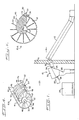
- the parts-segregator device or apparatus 10 ( Figure 1) is particularly useful in separating desired molded plastic parts from a jumbled flow of such parts, which jumbled flow includes not only the desired plastic parts but also the elongated plastic runners to which the desired parts were previously joined (i.e., when formed in the molding process).
- FIG 1 accordingly presents the typical, preferred location and orientation of segregator device or apparatus 10 as it would be placed in a modern, plastic-parts production facility.
- An upwardly-directed, inclined conveyor 12 carries the jumbled plastic parts and elongated runners, from molding equipment (not shown) in modling room 14, to an opening (also not shown) in wall 16 through which opening the plastic parts and elongated runners are dropped, by operation of conveyor 12, and thereafter are fed into a lead chute 18 (which is in a sorting and storage room 20).
- Lead chute 18 guides the jumbled flow of molded parts and elongated runners, under the influence of gravity, into segregator apparatus 10.
- the present apparatus 10 segregates the desired, molded parts from the undesired, elongated runners (in a manner which will be described in greater detail hereinbelow).
- the desired molded parts slide through segregator apparatus 10, still under the influence of gravity, and pass downwardly through exit chute 22 and from there into storage container 24.
- the undesired, elongated runners are lifted out of the jumbled flow of parts by the co-action of the several component parts (and structure) of the segregator apparatus 10. From segregator apparatus 10, the runners are caused to move -- by operation of the segregator apparatus 10 -- laterally into a side chute 26.
- the runners pass through the side chute 26, under the influence of gravity, and upon exiting side chute 26, drop into a grinder 28 which grinds the runners in preparation for subsequent re-use (e.g. for recycling the runners in the above-mentioned molded plastic parts-processing operation).
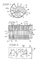
- the segregator apparatus 10A includes a main chute 30 having a cylindrical inner surface 32 ( Figure 2).
- Main chute 30 has a lead end 34 ( Figures 1 and 3) into which the jumbled plastic parts and elongated runners flow.
- Main chute 30 also has an exit end 36 ( Figures 1 and 3) from which the plastic parts alone exit the present parts-segregator apparatus or device.
- Main chute 30 is preferably tilted relative to the horizontal, as shown in Figure 1, so that gravity can be used to cause the jumbled flow of molded, desired plastic parts to pass through the main chute 30 of the segregator apparatus and into storage container 24.
- the segregator apparatus in particular, is specifically designed to segregate the desired parts (of predetermined dimension) from the jumbled flow of such parts and runners, wherein the runners have at least one dimension that is greater than the desired parts dimension.
- the cylindrical inner surface 32 of the first embodiment of the segregator apparatus 10A i.e., shown in Figures 2-5) is preferably quite smooth.
- the amount or degree of tilt should be sufficient for reliable flow through main chute 30, the amount or degree of tilt should not be too steep relative to the horizontal, because too great a tilt can slightly increase the chance of unintended passage of a runner all the way through chute 30, which is undesirable.
- a tilt of about 20° from the horizontal has been found to be acceptable in most instances.
- Main chute 30 has an opening 38 ( Figures 2 and 4) along its upper margin, and along a portion of one side thereof, which opening 38 is used for removal of the elongated runners after they are separated from the desired molded parts. Opening 38 extends from lateral edge 39 to upper edge 41 ( Figure 2), both of which edges 39 and 41 extend substantially parallel to the axis defined by shaft 40 ( Figures 2-5) for the full length of main chute 30.
- Shaft 40 supported by bearing means 62 ( Figure 3), is located within the space defined by main chute 30, and is substantially concentric with respect to cylindrical inner surface 32 ( Figure 2). Shaft 40, moreover, extends substantially along the full length of mainchute 30 ( Figure 3). Shaft 40 is caused to rotate in the bearing means 62 by operation of a suitable drive means such as the conventional drive motor 60. Drive motor 60, in turn, is operatively connected to shaft 40 by a suitable gear means such as the conventional gear box 66 and chain-drive means 64 (all shown in Figure 3).
- a suitable drive means such as the conventional drive motor 60.
- Drive motor 60 is operatively connected to shaft 40 by a suitable gear means such as the conventional gear box 66 and chain-drive means 64 (all shown in Figure 3).
- each of the hubs 42 has a circumferential surface 43 ( Figure 2); and a number of rod-like fingers 44, of suitable length and resiliency, are removably secured to hubs 42 along each one of the circumferential surfaces 43 ( Figures 2 and 3).
- the fingers 44 are preferably equally spaced along the circumferential surface 43 ( Figure 2).
- the fingers 44 preferably all have the same length, and all preferably extend along radii centered on their respective hubs 42 and on shaft 40.
- the length of the rotating fingers 44 preferably is chosen such that the distal ends 46 thereof are spaced closely adjacent to the inner surface 32 of the main chute 30 ( Figures 2 and 5). Because the rotating fingers 44 are preferably resilient, and therefore somewhat stiff yet relatively flexible, the length of the fingers 44 can be such that the distal ends 46 may even be in contact with the inner surface 32 during at least a portion of the rotation of the fingers 44 relative to the inner surface 32.
- the fingers 44 together with the shaft 40 and the hubs 42, form a three-dimensional array of rotating pickup-finger means, wherein the fingers 44 are positioned to substantially fill the confined space, in main chute 30, that is defined by the cylindrical inner surface 32.
- the three-dimensional pickup-finger array is caused to rotate in bearing means 62 by drive motor 60, with the distal ends 46 of the fingers 44 moving repeatedly into and out of the confined space (within main chute 30).
- Such rotation of the fingers 44 relative to the main chute 30 can be in a clockwise direction (i.e., as viewed from Figures 2 and 5) or in a counterclockwise direction (not shown), whichever is desired.
- the distal ends 46 of the rotating fingers 44 leaving the confined space in main chute 30 first pass upper edge 41, and thereafter pass through stripper elements 48 (described in greater detail below), and then finally pass lateral edge 39 before once again entering the confined space in main chute 30.
- the rotational speed of the fingers 44 will depend, to some extent, upon the total number of fingers 44, the diameter and length of the main chute 30, the circumferential spacing of the fingers 44 about individual hubs 42, and the axial spacing of the fingers 44 along the length of shaft 40, all relative to the predetermined dimensions of the desired parts and by-product runners.
- the rotational speed of the fingers 44 is generally about 1 to about 4 revolutions per minute (RPMs).
- the rotating fingers 44 of the three-dimensional array are spaced apart, at their distal ends 46 and at portions near such distal ends 46, by distances that are greater than the dimensions of the desired plastic parts that are to be separated from the jumbled flow (of plastic parts and elongated runners). Such spacing of rotating fingers 44, however, is preferably less than the length of the longest dimension of the elongated runners.
- parts-and runners molds can usually be readily designed to cause desired molded parts and by-product runners to have suitable dimensions to enable the present segregator apparatus to achieve the parts-separation result discussed herein.
- alternating hubs 42 have the respective rotating fingers 44 mounted thereon in a manner such that the rotating fingers 44 on any one hub 42 are radially aligned so as to be disposed between the fingers 44 on its nearest hub neighbors.
- This so-called "off-set" arrangement has been observed to substantially eliminate any unintended passage of a major portion of elongated runners through main chute 30 for many of the different-sized runners currently being segregated by the present segregator apparatus illustrated in Figures 2-5.
- the desired plastic parts that slide through main chute 30, while they might engage the rotating fingers 44 during such movement pass through the array of fingers 44, under the influence of gravity, and exit main chute 30 at its exit end 36.
- the elongated runners in main chute 30 are captured, by the rotating fingers 44, and thereafter are moved (by the rotating fingers 44), along the cylindrical inner surface 32, in a direction that is generally transverse to the direction of movement of the desired plastic parts, and finally, are lifted by the rotating fingers 44, for lateral removal from main chute 30, again utilizing the force of gravity.
- Such removal of the runners is accomplished by the interaction of the rotating array of pickup fingers 44 with an aligned array of stripper elements 48 ( Figures 2 and 3), which are sandwiched between (i.e., disposed so as to intermesh with) the several pluralities of rotatable fingers 44, as shown in Figure 3.
- Slots or lateral spaces 54 Figure 4
- the number, positioning and orientation of the several slots 54 is such that all of the rotating fingers 44 of each hub 42 turn or rotate within a corresponding one of the slots 54, as shown in Figure 3.
- each stripper element 48 is supported at one end portion thereof by shaft 40 and at the opposite end portion thereof by lateral edge 39 (of main chute lateral opening 38).
- the stripper elements 48 are preferably equally spaced longitudinally along shaft 40, intermeshing with hubs 42, as shown in Figure 3.
- the stripper elements 48 preferably have upwardly-facing arcuate surfaces 50 of convex curvature ( Figures 3-5), which surfaces are in alignment so that when viewed along the projected view ( Figures 2 and 5), the parts-stripper upper surfaces 50, taken together, are seen to form a runner reception surface onto which the elongated runners are deposited by the rotating action of the three-dimensional array of pickup fingers 44 and from which such runners slide laterally and downwardly into side chute 26 and ultimately into grinder 28.
- runner-reception surface that is formed by the upper surfaces 50 of stripper elements 48 extends from a position within the three-dimensional pickup-finger array to a lateral position outside such array, as shown in Figure 5.
- Such a runner-reception surface has a terminal edge 52 (as indicated in Figures 2 and 5) which is radially outwardly spaced from the terminal boundary of the array of rotating fingers 44 relative to shaft 40.
- a predetermined location on the downward slope of the runner-reception surface Figures 2 and 5 that is disposed generally downwardly so that the runners can slide, on the surfaces 50 and under the influence of gravity, as described above.
- the elongated runners which have been removed from the jumbled flow of by-product runners and plastic parts, are released from the three-dimensional array of rotating fingers 44, and thereby caused by the downward slope of the runner reception surface to slide into side chute 26 ( Figure 1).
- the degree to which the upper surface 50 tilts downwardly, from this point of intersection, is not critical but will depend, to a large extent, upon
- the rotating fingers 44 are preferably made from a suitably-stiff, resilient material such as nylon rods (that are generally circular in cross section), or are preferably made of other commercially-available relatively-rigid yet somewhat flexible, suitably-resilient material.
- a suitably-stiff, resilient material such as nylon rods (that are generally circular in cross section)
- the ability of the rotating fingers 44 to flex, to some extent, tends to prevent substantially any jams (or damage to the segregator apparatus or device) from occurring, as might be caused by unexpected conditions when utilizing conventional separation equipment.
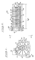
- the ribs 72 preferably arcuate ( Figure 6) and configured to conform substantially to the curvature of the cylindrical inner surface 32 of main chute 30, typically possess a height dimension sufficient to substantially block a major portion of the by-product runners 70 from freely sliding axially across the cylindrical inner surface 32 of main chute 30 ( Figure 8) when tilted relative to the horizontal (as shown in Figure 1), while allowing a substantial portion (i.e., virtually all) of the desired parts 74 to freely slide generally axially across inner surface 32 and into storage container 24 ( Figure 1) as described above. That is, the ribs 72 do not possess so great a height dimension as to block the above-described free-flow of the desired parts 74 longitudinally down the main chute 30, which result is desirable. (The desired parts 74 and by-product runners 70 are not shown in Figures 6 and 7, but only in Figure 8, for reasons of clarity.)
- the molds (not shown) that are used to produce not only the desired parts 74 but also the by-product runners 70 are specifically designed -- as is well-known in the art -- so that the runner 70 is relatively thinner (at least in one dimension) than the desired parts 74.
- the ribs 72 preferably removably affixed to the main chute inner surface 32, are suitably dimensioned (relative to the desired part and by-product runner dimensions) to achieve the result discussed above.
- each stationary finger 76 preferably being fixed to a respective stripper element 48.
- the stationary fingers 76 intermesh with the rotating fingers 44 (as shown in Figure 7), for causing a substantial portion (i.e., virtually all) of the by-product runners 70 to separate from the desired parts 74.
- the desired parts 74 can become entangled with the by-product runners 70.
- one such desired part 74 may have an opening through which an end portion of another such runner 70 is disposed; and this, at times, has been observed to cause the desired part 74 to be removed from the main chute 30 along with the runner 70 (through operation of the rotating fingers 44, as described above). That is, a part 74 having such an opening can occasionally be observed to be carried along with a runner (such as in the case where a desired part is impaled upon an end portion of a runner), with the result being that the runner together with the desired part (impaled thereon) are removed by operation of the pickup-finger array. In both types of situations, the location and positioning of the stationary fingers 76 relative to the rotating fingers 44 has been observed to positively cause separation of the desired part from the by-product runner.
- the stationary fingers 76 are preferably rod-like, are preferably circular in cross section, have distal ends that are spaced preferably relatively closely to the cylindrical inner surface 32 of main chute 30 (as shown in Figure 7), and are preferably made of the same resilient material as the rotating fingers 44. Moreover, the stationary fingers 76 preferably have a relatively smaller diameter than the rotating fingers 44 so that the stationary fingers 76 flex (before the rotating fingers 44) when opposed, for example, by rotational movement of the rotating fingers 44 about shaft 40.
- this feature of the present invention not only enables the rotating and stationary fingers 44 and 76 to function cooperatively to cause the runners 70 and desired parts 74 to separate, as described above, but also enables the runners 70 to be urged by the rotating fingers 44 through the array of flexing stationary fingers 76, whereupon the rotating-finger array selectively removes the runners 70 from thee above-defined confined space (in main chute 30) and thereafter deposits the runners 70 on the upwardly-facing surfaces 50 of the stripper elements 46, substantially in the manner described above.
- each stationary fingers 76 is preferably removably press-fitted into a respective stripper element 48, and disposed generally outwardly therefrom, as shown in Figures 6 and 7. While the stationary fingers 76 can be disposed radially outward on stripper element 48 relative to shaft 40, the preferred orientation of the stationary fingers 76 is skewed - i.e., away from a "true" radial disposition-in the direction of rotation of the rotating fingers 44 (which is clockwise, when viewed from the down-stream end, as mentioned above) as is shown in Figure 6.
Landscapes
- Processing And Handling Of Plastics And Other Materials For Molding In General (AREA)
- Specific Conveyance Elements (AREA)
- Feeding Of Articles To Conveyors (AREA)
- Sorting Of Articles (AREA)
Applications Claiming Priority (2)
| Application Number | Priority Date | Filing Date | Title |
|---|---|---|---|
| US07/013,085 US4752009A (en) | 1986-01-23 | 1987-02-10 | Apparatus for segregating parts |
| US13085 | 1987-02-10 |
Publications (2)
| Publication Number | Publication Date |
|---|---|
| EP0278249A2 true EP0278249A2 (fr) | 1988-08-17 |
| EP0278249A3 EP0278249A3 (fr) | 1989-06-07 |
Family
ID=21758230
Family Applications (1)
| Application Number | Title | Priority Date | Filing Date |
|---|---|---|---|
| EP88100455A Ceased EP0278249A3 (fr) | 1987-02-10 | 1988-01-14 | Dispositif pour la séparation d'éléments |
Country Status (4)
| Country | Link |
|---|---|
| US (1) | US4752009A (fr) |
| EP (1) | EP0278249A3 (fr) |
| JP (1) | JPS63200876A (fr) |
| BR (1) | BR8800146A (fr) |
Cited By (1)
| Publication number | Priority date | Publication date | Assignee | Title |
|---|---|---|---|---|
| CN109365328A (zh) * | 2018-10-18 | 2019-02-22 | 广州达意隆包装机械股份有限公司 | 一种灌装机的剔除机构 |
Families Citing this family (6)
| Publication number | Priority date | Publication date | Assignee | Title |
|---|---|---|---|---|
| US4854454A (en) * | 1986-01-23 | 1989-08-08 | S. C. Johnson & Son, Inc. | Apparatus and method for segregating parts |
| US6003680A (en) * | 1996-10-01 | 1999-12-21 | Bedminster Bioconversion Corp. | Waste separation device |
| USD396804S (en) | 1997-06-23 | 1998-08-11 | Inline Plastics Corporation | Product holding and displaying container |
| USD398227S (en) | 1997-06-23 | 1998-09-15 | Inline Plastics Corporation | Product holding and displaying container |
| USD398525S (en) | 1997-06-23 | 1998-09-22 | Inline Plastics Corporation | Product holding and displaying container |
| US11129335B2 (en) * | 2019-05-21 | 2021-09-28 | Cnh Industrial America Llc | Shaft shield for rotary conveyor |
Family Cites Families (18)
| Publication number | Priority date | Publication date | Assignee | Title |
|---|---|---|---|---|
| CA679042A (en) * | 1964-01-28 | J. Jamal Victor | Metal separating apparatus | |
| US1012046A (en) * | 1911-12-19 | Anderson Barn Grover Mfg Co | Conveyer. | |
| US781616A (en) * | 1904-11-21 | 1905-01-31 | Joseph P Owens | Corn-silking machine. |
| US1474566A (en) * | 1921-08-29 | 1923-11-20 | George G Schorer | Apparatus for separating fibrous and nonfibrous materials in food products |
| US2114263A (en) * | 1934-10-16 | 1938-04-12 | James G Heaslet | Apparatus for separation of vegetables |
| US2710097A (en) * | 1953-05-18 | 1955-06-07 | Hawaiian Sugar Planters Assoc | Apparatus for recovering sugar cane from leaf trash |
| BE559107A (fr) * | 1956-07-11 | 1957-07-31 | ||
| US3663142A (en) * | 1970-02-27 | 1972-05-16 | Nylon Products Corp | Plastic injection molding system |
| US3661256A (en) * | 1970-05-06 | 1972-05-09 | Burroughs Corp | Mail handling and separating apparatus |
| US3651938A (en) * | 1970-05-18 | 1972-03-28 | Lemay Machine Co | Automatic article segregation |
| US3982632A (en) * | 1975-06-23 | 1976-09-28 | Owens-Illinois, Inc. | Thermoplastic injection runner transfer system |
| US4224350A (en) * | 1979-04-19 | 1980-09-23 | Frito-Lay, Inc. | Apparatus and method for selectively ejecting malformed articles |
| US4232506A (en) * | 1979-06-25 | 1980-11-11 | The Regents Of The University Of California | Method and apparatus for recovering tomatoes from severed vines, employing a rotated and oscillated shaker |
| US4264012A (en) * | 1979-10-01 | 1981-04-28 | Automated Assemblies Corp. | Segregation of molded parts |
| US4454030A (en) * | 1981-06-26 | 1984-06-12 | Nelmor Company, Inc. | Sprue separator |
| US4484684A (en) * | 1982-05-17 | 1984-11-27 | Tetreault Merritt D | Parts separator |
| US4541532A (en) * | 1983-05-25 | 1985-09-17 | Wilson William A | Side kick solids separator |
| US4676380A (en) * | 1986-01-23 | 1987-06-30 | S. C. Johnson & Son, Inc. | Apparatus and method for segregating parts |
-
1987
- 1987-02-10 US US07/013,085 patent/US4752009A/en not_active Expired - Fee Related
-
1988
- 1988-01-14 EP EP88100455A patent/EP0278249A3/fr not_active Ceased
- 1988-01-14 JP JP63006730A patent/JPS63200876A/ja active Pending
- 1988-01-15 BR BR8800146A patent/BR8800146A/pt unknown
Cited By (1)
| Publication number | Priority date | Publication date | Assignee | Title |
|---|---|---|---|---|
| CN109365328A (zh) * | 2018-10-18 | 2019-02-22 | 广州达意隆包装机械股份有限公司 | 一种灌装机的剔除机构 |
Also Published As
| Publication number | Publication date |
|---|---|
| US4752009A (en) | 1988-06-21 |
| JPS63200876A (ja) | 1988-08-19 |
| BR8800146A (pt) | 1988-08-30 |
| EP0278249A3 (fr) | 1989-06-07 |
Similar Documents
| Publication | Publication Date | Title |
|---|---|---|
| US4207986A (en) | Apparatus for separating plastic film from paper particularly adapted for use in waste recycling systems | |
| JP4061085B2 (ja) | 部品整送装置 | |
| US4541531A (en) | Rotary separator | |
| EP0278249A2 (fr) | Dispositif pour la séparation d'éléments | |
| WO1995031377A1 (fr) | Systeme de dechirage de sacs | |
| EP0548216A1 (fr) | Empileuse rotative. | |
| US3086639A (en) | Method and machine for similarly arranging open-topped containers or the like | |
| US4854454A (en) | Apparatus and method for segregating parts | |
| EP0162915A4 (fr) | Separation de parties moulees de connecteurs. | |
| NL9200544A (nl) | Inrichting voor het op grootte sorteren van knolvormige vruchten. | |
| GB2085417A (en) | Improvements in or relating to devices for separating components | |
| US4245733A (en) | Feeder | |
| US4484684A (en) | Parts separator | |
| EP0647489A1 (fr) | Dispositif pour éliminer un matériau adhésif d'un sable de fonderie | |
| EP0230321A2 (fr) | Procédé et dispositif de séparation d'éléments | |
| EP0345036A1 (fr) | Convoyeur avec distributeur | |
| EP0105431B1 (fr) | Dispositif pour séparer des carottes de pièces moulées de différentes formes et dimensions | |
| US4264012A (en) | Segregation of molded parts | |
| USRE32823E (en) | Apparatus and method for segregating parts | |
| EP0561100A1 (fr) | Dispositif pour accumuler des feuilles dans des piles avec un nombre d'éléments prédéterminé | |
| US5284236A (en) | Stacked rubber tire separation-transport apparatus | |
| US4023478A (en) | Nut husking apparatus | |
| EP0001172A1 (fr) | Appareil et procédé de classement de solides hétérogènes | |
| JPH07163946A (ja) | サイズ選別機 | |
| JPH0664736A (ja) | 部品類供給方法及び装置 |
Legal Events
| Date | Code | Title | Description |
|---|---|---|---|
| PUAI | Public reference made under article 153(3) epc to a published international application that has entered the european phase |
Free format text: ORIGINAL CODE: 0009012 |
|
| AK | Designated contracting states |
Kind code of ref document: A2 Designated state(s): DE ES FR GB IT NL |
|
| PUAL | Search report despatched |
Free format text: ORIGINAL CODE: 0009013 |
|
| AK | Designated contracting states |
Kind code of ref document: A3 Designated state(s): DE ES FR GB IT NL |
|
| 17P | Request for examination filed |
Effective date: 19890713 |
|
| 17Q | First examination report despatched |
Effective date: 19900816 |
|
| STAA | Information on the status of an ep patent application or granted ep patent |
Free format text: STATUS: THE APPLICATION HAS BEEN REFUSED |
|
| 18R | Application refused |
Effective date: 19910914 |