EP0278480B2 - Procédé de revêtement d'articles plastiques par une couche de carbone par dépÔt chimique en phase vapeur à micro-ondes - Google Patents
Procédé de revêtement d'articles plastiques par une couche de carbone par dépÔt chimique en phase vapeur à micro-ondes Download PDFInfo
- Publication number
- EP0278480B2 EP0278480B2 EP88101879A EP88101879A EP0278480B2 EP 0278480 B2 EP0278480 B2 EP 0278480B2 EP 88101879 A EP88101879 A EP 88101879A EP 88101879 A EP88101879 A EP 88101879A EP 0278480 B2 EP0278480 B2 EP 0278480B2
- Authority
- EP
- European Patent Office
- Prior art keywords
- carbon
- microwave
- reaction chamber
- film
- gas
- Prior art date
- Legal status (The legal status is an assumption and is not a legal conclusion. Google has not performed a legal analysis and makes no representation as to the accuracy of the status listed.)
- Expired - Lifetime
Links
- 229910052799 carbon Inorganic materials 0.000 title claims description 46
- OKTJSMMVPCPJKN-UHFFFAOYSA-N Carbon Chemical compound [C] OKTJSMMVPCPJKN-UHFFFAOYSA-N 0.000 title claims description 44
- 238000000034 method Methods 0.000 title claims description 34
- 239000004033 plastic Substances 0.000 title claims description 15
- 229920003023 plastic Polymers 0.000 title claims description 15
- 238000000576 coating method Methods 0.000 title claims description 12
- 239000011248 coating agent Substances 0.000 title claims description 11
- 239000007789 gas Substances 0.000 claims description 46
- UFHFLCQGNIYNRP-UHFFFAOYSA-N Hydrogen Chemical compound [H][H] UFHFLCQGNIYNRP-UHFFFAOYSA-N 0.000 claims description 21
- 239000001257 hydrogen Substances 0.000 claims description 17
- 229910052739 hydrogen Inorganic materials 0.000 claims description 17
- 230000008569 process Effects 0.000 claims description 15
- 238000000151 deposition Methods 0.000 claims description 13
- 150000001722 carbon compounds Chemical class 0.000 claims description 12
- HSFWRNGVRCDJHI-UHFFFAOYSA-N Acetylene Chemical compound C#C HSFWRNGVRCDJHI-UHFFFAOYSA-N 0.000 claims description 9
- 125000000219 ethylidene group Chemical group [H]C(=[*])C([H])([H])[H] 0.000 claims description 4
- 230000003993 interaction Effects 0.000 claims description 3
- 239000000126 substance Substances 0.000 claims description 3
- 150000001875 compounds Chemical class 0.000 claims description 2
- 230000001939 inductive effect Effects 0.000 claims description 2
- 239000010408 film Substances 0.000 description 53
- 239000000758 substrate Substances 0.000 description 25
- 229910003460 diamond Inorganic materials 0.000 description 20
- 239000010432 diamond Substances 0.000 description 20
- IJGRMHOSHXDMSA-UHFFFAOYSA-N Atomic nitrogen Chemical compound N#N IJGRMHOSHXDMSA-UHFFFAOYSA-N 0.000 description 14
- VNWKTOKETHGBQD-UHFFFAOYSA-N methane Chemical compound C VNWKTOKETHGBQD-UHFFFAOYSA-N 0.000 description 13
- 230000005684 electric field Effects 0.000 description 11
- 230000008021 deposition Effects 0.000 description 10
- 238000002474 experimental method Methods 0.000 description 9
- PZNSFCLAULLKQX-UHFFFAOYSA-N Boron nitride Chemical compound N#B PZNSFCLAULLKQX-UHFFFAOYSA-N 0.000 description 8
- 238000010586 diagram Methods 0.000 description 8
- 239000002245 particle Substances 0.000 description 8
- 229910052582 BN Inorganic materials 0.000 description 7
- 239000010409 thin film Substances 0.000 description 7
- QGZKDVFQNNGYKY-UHFFFAOYSA-N ammonia Natural products N QGZKDVFQNNGYKY-UHFFFAOYSA-N 0.000 description 6
- 229910052757 nitrogen Inorganic materials 0.000 description 6
- 125000005843 halogen group Chemical group 0.000 description 5
- 230000001965 increasing effect Effects 0.000 description 5
- 229910052782 aluminium Inorganic materials 0.000 description 4
- 229910003481 amorphous carbon Inorganic materials 0.000 description 4
- -1 i.e. Inorganic materials 0.000 description 4
- 229910017464 nitrogen compound Inorganic materials 0.000 description 4
- 150000002830 nitrogen compounds Chemical class 0.000 description 4
- ZOXJGFHDIHLPTG-UHFFFAOYSA-N Boron Chemical compound [B] ZOXJGFHDIHLPTG-UHFFFAOYSA-N 0.000 description 3
- 241001364096 Pachycephalidae Species 0.000 description 3
- 239000004411 aluminium Substances 0.000 description 3
- XAGFODPZIPBFFR-UHFFFAOYSA-N aluminium Chemical compound [Al] XAGFODPZIPBFFR-UHFFFAOYSA-N 0.000 description 3
- 230000004888 barrier function Effects 0.000 description 3
- 229910052796 boron Inorganic materials 0.000 description 3
- 230000005284 excitation Effects 0.000 description 3
- 239000000203 mixture Substances 0.000 description 3
- 239000010935 stainless steel Substances 0.000 description 3
- 229910001220 stainless steel Inorganic materials 0.000 description 3
- XKRFYHLGVUSROY-UHFFFAOYSA-N Argon Chemical compound [Ar] XKRFYHLGVUSROY-UHFFFAOYSA-N 0.000 description 2
- LFQSCWFLJHTTHZ-UHFFFAOYSA-N Ethanol Chemical compound CCO LFQSCWFLJHTTHZ-UHFFFAOYSA-N 0.000 description 2
- XEEYBQQBJWHFJM-UHFFFAOYSA-N Iron Chemical compound [Fe] XEEYBQQBJWHFJM-UHFFFAOYSA-N 0.000 description 2
- OKKJLVBELUTLKV-UHFFFAOYSA-N Methanol Chemical compound OC OKKJLVBELUTLKV-UHFFFAOYSA-N 0.000 description 2
- XYFCBTPGUUZFHI-UHFFFAOYSA-N Phosphine Chemical compound P XYFCBTPGUUZFHI-UHFFFAOYSA-N 0.000 description 2
- 239000000956 alloy Substances 0.000 description 2
- 229910045601 alloy Inorganic materials 0.000 description 2
- 229910021529 ammonia Inorganic materials 0.000 description 2
- 230000015572 biosynthetic process Effects 0.000 description 2
- 238000005094 computer simulation Methods 0.000 description 2
- 229910001873 dinitrogen Inorganic materials 0.000 description 2
- 238000009826 distribution Methods 0.000 description 2
- 238000005530 etching Methods 0.000 description 2
- 235000019441 ethanol Nutrition 0.000 description 2
- 125000004435 hydrogen atom Chemical group [H]* 0.000 description 2
- 238000004519 manufacturing process Methods 0.000 description 2
- 230000003287 optical effect Effects 0.000 description 2
- 238000005268 plasma chemical vapour deposition Methods 0.000 description 2
- 239000011347 resin Substances 0.000 description 2
- 229920005989 resin Polymers 0.000 description 2
- 210000000707 wrist Anatomy 0.000 description 2
- BVKZGUZCCUSVTD-UHFFFAOYSA-L Carbonate Chemical compound [O-]C([O-])=O BVKZGUZCCUSVTD-UHFFFAOYSA-L 0.000 description 1
- VGGSQFUCUMXWEO-UHFFFAOYSA-N Ethene Chemical compound C=C VGGSQFUCUMXWEO-UHFFFAOYSA-N 0.000 description 1
- 239000005977 Ethylene Substances 0.000 description 1
- PXGOKWXKJXAPGV-UHFFFAOYSA-N Fluorine Chemical compound FF PXGOKWXKJXAPGV-UHFFFAOYSA-N 0.000 description 1
- 239000004698 Polyethylene Substances 0.000 description 1
- XUIMIQQOPSSXEZ-UHFFFAOYSA-N Silicon Chemical compound [Si] XUIMIQQOPSSXEZ-UHFFFAOYSA-N 0.000 description 1
- 238000005299 abrasion Methods 0.000 description 1
- 230000009471 action Effects 0.000 description 1
- 229910052786 argon Inorganic materials 0.000 description 1
- 125000004429 atom Chemical group 0.000 description 1
- 239000011230 binding agent Substances 0.000 description 1
- 150000001639 boron compounds Chemical class 0.000 description 1
- 125000004432 carbon atom Chemical group C* 0.000 description 1
- 235000019994 cava Nutrition 0.000 description 1
- 229910052804 chromium Inorganic materials 0.000 description 1
- 239000004020 conductor Substances 0.000 description 1
- 238000001816 cooling Methods 0.000 description 1
- 239000013078 crystal Substances 0.000 description 1
- 238000005034 decoration Methods 0.000 description 1
- 230000007423 decrease Effects 0.000 description 1
- 230000007547 defect Effects 0.000 description 1
- 239000002019 doping agent Substances 0.000 description 1
- 235000012489 doughnuts Nutrition 0.000 description 1
- 238000010891 electric arc Methods 0.000 description 1
- 238000010894 electron beam technology Methods 0.000 description 1
- 125000002534 ethynyl group Chemical group [H]C#C* 0.000 description 1
- 239000011737 fluorine Substances 0.000 description 1
- 229910052731 fluorine Inorganic materials 0.000 description 1
- 125000001153 fluoro group Chemical group F* 0.000 description 1
- 239000011521 glass Substances 0.000 description 1
- 229910002804 graphite Inorganic materials 0.000 description 1
- 239000010439 graphite Substances 0.000 description 1
- 229910021385 hard carbon Inorganic materials 0.000 description 1
- 239000001307 helium Substances 0.000 description 1
- 229910052734 helium Inorganic materials 0.000 description 1
- SWQJXJOGLNCZEY-UHFFFAOYSA-N helium atom Chemical compound [He] SWQJXJOGLNCZEY-UHFFFAOYSA-N 0.000 description 1
- BHEPBYXIRTUNPN-UHFFFAOYSA-N hydridophosphorus(.) (triplet) Chemical compound [PH] BHEPBYXIRTUNPN-UHFFFAOYSA-N 0.000 description 1
- 239000012535 impurity Substances 0.000 description 1
- 229910052741 iridium Inorganic materials 0.000 description 1
- 229910052742 iron Inorganic materials 0.000 description 1
- 239000000463 material Substances 0.000 description 1
- 238000002844 melting Methods 0.000 description 1
- 230000008018 melting Effects 0.000 description 1
- 229910052759 nickel Inorganic materials 0.000 description 1
- QJGQUHMNIGDVPM-UHFFFAOYSA-N nitrogen group Chemical group [N] QJGQUHMNIGDVPM-UHFFFAOYSA-N 0.000 description 1
- 229910000069 nitrogen hydride Inorganic materials 0.000 description 1
- 229910052763 palladium Inorganic materials 0.000 description 1
- 239000012071 phase Substances 0.000 description 1
- 229910000073 phosphorus hydride Inorganic materials 0.000 description 1
- 229910052697 platinum Inorganic materials 0.000 description 1
- 229920000515 polycarbonate Polymers 0.000 description 1
- 239000004417 polycarbonate Substances 0.000 description 1
- 229920000573 polyethylene Polymers 0.000 description 1
- 229920002635 polyurethane Polymers 0.000 description 1
- 239000004814 polyurethane Substances 0.000 description 1
- 230000001902 propagating effect Effects 0.000 description 1
- 239000010453 quartz Substances 0.000 description 1
- 239000004065 semiconductor Substances 0.000 description 1
- 229910052710 silicon Inorganic materials 0.000 description 1
- 239000010703 silicon Substances 0.000 description 1
- VYPSYNLAJGMNEJ-UHFFFAOYSA-N silicon dioxide Inorganic materials O=[Si]=O VYPSYNLAJGMNEJ-UHFFFAOYSA-N 0.000 description 1
- 229910052719 titanium Inorganic materials 0.000 description 1
- 229910052720 vanadium Inorganic materials 0.000 description 1
- 239000012808 vapor phase Substances 0.000 description 1
- XLYOFNOQVPJJNP-UHFFFAOYSA-N water Substances O XLYOFNOQVPJJNP-UHFFFAOYSA-N 0.000 description 1
Images


Classifications
-
- C—CHEMISTRY; METALLURGY
- C23—COATING METALLIC MATERIAL; COATING MATERIAL WITH METALLIC MATERIAL; CHEMICAL SURFACE TREATMENT; DIFFUSION TREATMENT OF METALLIC MATERIAL; COATING BY VACUUM EVAPORATION, BY SPUTTERING, BY ION IMPLANTATION OR BY CHEMICAL VAPOUR DEPOSITION, IN GENERAL; INHIBITING CORROSION OF METALLIC MATERIAL OR INCRUSTATION IN GENERAL
- C23C—COATING METALLIC MATERIAL; COATING MATERIAL WITH METALLIC MATERIAL; SURFACE TREATMENT OF METALLIC MATERIAL BY DIFFUSION INTO THE SURFACE, BY CHEMICAL CONVERSION OR SUBSTITUTION; COATING BY VACUUM EVAPORATION, BY SPUTTERING, BY ION IMPLANTATION OR BY CHEMICAL VAPOUR DEPOSITION, IN GENERAL
- C23C14/00—Coating by vacuum evaporation, by sputtering or by ion implantation of the coating forming material
- C23C14/22—Coating by vacuum evaporation, by sputtering or by ion implantation of the coating forming material characterised by the process of coating
- C23C14/24—Vacuum evaporation
-
- C—CHEMISTRY; METALLURGY
- C23—COATING METALLIC MATERIAL; COATING MATERIAL WITH METALLIC MATERIAL; CHEMICAL SURFACE TREATMENT; DIFFUSION TREATMENT OF METALLIC MATERIAL; COATING BY VACUUM EVAPORATION, BY SPUTTERING, BY ION IMPLANTATION OR BY CHEMICAL VAPOUR DEPOSITION, IN GENERAL; INHIBITING CORROSION OF METALLIC MATERIAL OR INCRUSTATION IN GENERAL
- C23C—COATING METALLIC MATERIAL; COATING MATERIAL WITH METALLIC MATERIAL; SURFACE TREATMENT OF METALLIC MATERIAL BY DIFFUSION INTO THE SURFACE, BY CHEMICAL CONVERSION OR SUBSTITUTION; COATING BY VACUUM EVAPORATION, BY SPUTTERING, BY ION IMPLANTATION OR BY CHEMICAL VAPOUR DEPOSITION, IN GENERAL
- C23C16/00—Chemical coating by decomposition of gaseous compounds, without leaving reaction products of surface material in the coating, i.e. chemical vapour deposition [CVD] processes
- C23C16/22—Chemical coating by decomposition of gaseous compounds, without leaving reaction products of surface material in the coating, i.e. chemical vapour deposition [CVD] processes characterised by the deposition of inorganic material, other than metallic material
- C23C16/26—Deposition of carbon only
-
- C—CHEMISTRY; METALLURGY
- C23—COATING METALLIC MATERIAL; COATING MATERIAL WITH METALLIC MATERIAL; CHEMICAL SURFACE TREATMENT; DIFFUSION TREATMENT OF METALLIC MATERIAL; COATING BY VACUUM EVAPORATION, BY SPUTTERING, BY ION IMPLANTATION OR BY CHEMICAL VAPOUR DEPOSITION, IN GENERAL; INHIBITING CORROSION OF METALLIC MATERIAL OR INCRUSTATION IN GENERAL
- C23C—COATING METALLIC MATERIAL; COATING MATERIAL WITH METALLIC MATERIAL; SURFACE TREATMENT OF METALLIC MATERIAL BY DIFFUSION INTO THE SURFACE, BY CHEMICAL CONVERSION OR SUBSTITUTION; COATING BY VACUUM EVAPORATION, BY SPUTTERING, BY ION IMPLANTATION OR BY CHEMICAL VAPOUR DEPOSITION, IN GENERAL
- C23C16/00—Chemical coating by decomposition of gaseous compounds, without leaving reaction products of surface material in the coating, i.e. chemical vapour deposition [CVD] processes
- C23C16/44—Chemical coating by decomposition of gaseous compounds, without leaving reaction products of surface material in the coating, i.e. chemical vapour deposition [CVD] processes characterised by the method of coating
- C23C16/50—Chemical coating by decomposition of gaseous compounds, without leaving reaction products of surface material in the coating, i.e. chemical vapour deposition [CVD] processes characterised by the method of coating using electric discharges
- C23C16/511—Chemical coating by decomposition of gaseous compounds, without leaving reaction products of surface material in the coating, i.e. chemical vapour deposition [CVD] processes characterised by the method of coating using electric discharges using microwave discharges
Definitions
- ECR CVD has attracted the interests of researchers as a new method of manufacturing thin films, particularly amorphous thin films.
- Matsuo et al discloses one type of such an ECR CVD apparatus in US-A-4,401,054.
- This recent technique utilizes microwaves to energize a reactive gas into a plasma state by virtue of a magnetic field which functions to pinch the plasma gas within the excitation space. With this configuration, the reactive gas can absorb the energy of the microwaves.
- a substrate to be coated is located distant from the excitation space (resonating space) for preventing the same from being sputtered.
- the energized gas is showered on the substrate from the resonating space.
- the pressure in a resonating space is kept at 0.13 Pa to 0.0013 Pa (1 x 10⁻³ to 1 x 10⁻⁵ Torr) at which electrons can be considered as independent particles and resonate with a microwave in an electron cyclotron resonance on a certain surface on which the magnetic field takes a particular strength required for ECR.
- the excited plasma is extracted from the resonating space, by means of a divergent magnetic field. to a deposition space which is located distant from the resonating space and in which is disposed a substrate to be coated.
- a carbon coating is implemented for several purposes.
- the carbon coating functions to reinforce the strength of the components and to endow the components with resistance to abrasion.
- ornaments. such as buttons, frames of spectacles and some parts of watches are coated, the carbon coatings become decoration.
- this object is attained with a method of coating a plastic surface with a carbon film comprising
- nitrogen and/or a nitrogen compound gas can be inputted to the reaction chamber.
- the inputted nitrogen functions to prevent lattice defects from growing by virtue of external or internal stress.
- a boron compound is also inputted together with the nitrogen compound, the adhesivity of carbon deposited is improved.
- Boron nitride appears to be the binder between the carbon and the underlying substrate to be coated such as parts of a watch.
- carbon and boron nitride are deposited on the substrate in the form of crystalline grain particles or a layer containing nitrogen and boron in an amount of less than 10%.
- the method of the invention utilizes a mixed cyclotron resonance.
- the sonic action of the reactive gas itself must be taken into consideration as a non-negligible perturbation besides the interaction between respective particles of the reactive gas and magnetic field and microwave. and therefore charged particles of a reactive gas can be absorbed in a relatively wide resonating space.
- the pressure is maintained higher than 0.4 kPa (3 Torr).
- the pressure in a reaction chamber is elevated 10-105 times as high as that of the prior art.
- the mixed resonance can be established by increasing the pressure after ECR takes place at a low pressure.
- a plasma gas is placed in ECR condition at 0.13 to 0.0013 Pa (1 x 10 ⁇ 3 to 1 x 10⁻⁵ Torr) by inputting a microwave under the existence of magnetic field. Then a reactive gas is inputted into the plasma gas so that the pressure is elevated to 0.013 to 39.9 kPa (0.1 to 300 Torr) and the resonance is changed from ECR to MCR (Mixed Cyclotron Resonance). The MCR appears together with the whistler mode. Carbon can be decomposed and undergo a necessary reaction at only such a comparatively high pressure. In process, diamond is likely to grow selectively on convex surfaces.
- the hardness of the diamond formed by the present invention is 1.3 to 3.0 times as high as that of diamond which has been made by a prior art vapor phase method.
- film is used in a broad meaning. If a number of diamond particles are finely distributed on a surface, such a diamond coating will be called “film.” Of Course, a uniform and continuous amorphous layer is called a "film.”
- such parts can be made of plastics and aluminium or its alloy which have attractive processabilities so that the wrist watch is strongly formed and light weighted.
- the electric field tends to be concentrated at the corners of the parts during the process, and therefore such corners particularly exposed to external impacts when used can be coated with a carbon film thicker than that on a flat surface by a factor of two.
- Fig.1 is a cross sectional view showing a CVD apparatus for coating plastic objects in accordance with the present invention.
- Fig.2(A) is a graphical diagram showing the profile of the equipotential surfaces of the magnetic field in cross section in accordance with a computer simulation.
- Fig.2(B) is a graphical diagram showing the strength of the electric field in accordance with a computer simulation.
- Figs.3(A) and 3(B) are graphical diagrams showing equipotential surfaces in terms of magnetic field and electric field of microwave propagating in a resonating space respectively.
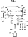
- Fig.4 is a cross sectional view showing a further CVD apparatus for forming a carbon film in accordance with the invention.
- the apparatus comprises a reaction chamber in which a plasma generating space 1 and an auxiliary space 2 are defined and which can be held at an appropriate pressure, a microwave generator 4, electro-magnets 5 and 5' which are supplied with an electric power from a power supply 25, and a water cooling system 18.
- the plasma generating space 1 has a circular cross section.
- a hollow cylinder 10' having inward-turned brims is rotatably supported in the space so that a microwave emitted from the microwave generator 4 passes through the cylinder along its axis.
- the cylinder 10' is made of a stainless steel or a quartz and turned by means of a motor 16 through a gear.
- an evacuating system comprising a turbo molecular pump 8 and a rotary pump 14 which are connected with the reaction chamber through pressure controlling valves 11, 12 and 13. The process with this apparatus is carried out as follow.
- Objects 10 to be coated with a carbon film are plastics such as e.g., gear-wheels with 3-10 mm in diameter and 0.2-2.0 mm in thickness, screws, buttons, toy parts which need sufficient hardness, frames of spectacles, the entire external surface of ball pens or propelling pencils, or other ornaments having various external shapes which are to be coated with diamond, or parts of watches such as frames made of plastics, windows made of glasses or plastics.
- the objects 10 are put in the cylinder 10' which is to turn at 0.1-10 rpm during the process. At the same time, the objects 10 are heated to a certain elevated temperature at which the objects are not damaged.
- the elevated temperature is, e.g., 150-300°C; for aluminium or its alloy objects, e.g., 400-700°C; for iron, stainless steel or other metallic objects, e.g., 700-1000°C.
- the cylinder 10' although the means is not illustrated in the figure, is shaken by micro-vibration of 100Hz-10KHz. By the turning and the vibration, the surfaces of the objects exposed to the reactive gas are always switching during process.
- the reaction chamber is evacuated by the turbo molecular pump 8 and the rotary pump to 0.13 x 10 ⁇ 3 Pa (1 x 10 ⁇ 6 Torr) or lower.
- argon, helium or hydrogen as a non-productive gas is introduced to the reaction chamber from a gas introducing system 6 at 30SCCM, and a microwave of 2.45GHz is emitted from the microwave generator at 500 W through a microwave introduction window 15 to the plasma generating space 1 which is subjected to an magnetic field of about 0.2 t (2 K Gauss) induced by the magnets 5 and 5'.
- the pressure of the non-productive gas is 0.013 Pa (1 x 10 ⁇ 4 Torr).
- a plasma is generated in the space 1 at a high density by the energy of the microwave.
- the surfaces of the objects 10 are cleaned by high energy elecrons and non-productive atoms.
- C2H2, C2H4 and/or CH4 are introduced at 200 SCCM through a introduction system 7.
- a large amount of hydrogen is introduced into the reaction chamber so that the carbon compound gas is diluted with the hydrogen to 0.1-2.0 %.
- the pressure of the reactibn chamber is maintained at 0.013-39.9 kPa (0.1-300 Torr), preferably 0.40-4.00 kPa (3-30 Torr), e.g., 1.3 kPa (10 Torr).
- the reactive gas is excited by the energy of the microwave in the same manner as carried out with the non-productive gas explained in the foregoing description.
- carbon is deposited in the form of a diamond film or an i-carbon (insulated carbon consisting of crystalline particles) film on the objects 10.
- Fig.2(A) is a graphical diagram showing the distribution of the magnetic field on the region 30 in Fig.1. Curves on the diagram are plotted along equipotential surfaces and given numerals indicate the strengths on the respective curves of the magnetic field induced by the magnets 5 and 5' having a power of 0.2 t (2000 Gauss). By adjusting the power of the magnets 5 and 5', the strength of the magnetic field can be controlled so that the magnetic field becomes largely uniform over the surface to be coated which is located in the region 100 where the magnetic field (8.75 x 10 ⁇ ⁇ 1.85 x 10 ⁇ t) ((875 ⁇ 185 Gauss)) and the electric field interact.
- reference 26 designates the equipotential surface of 8.75 x 10 ⁇ t (875 Gauss) at which the ECR (electron cyclotron resonance) condition between the magnetic field and the frequency of the microwave is satisfied.
- ECR electron cyclotron resonance
- MCR mixed cyclotron resonance
- Fig.2(B) is a graphical diagram of which the X-axis corresponds to that of Fig.2(A) and shows the strength of the electric field of the microwave in the plasma generating space 1. The strength of the electric field takes its maximum value in the regions 100 and 100'.
- a uniform film can be formed on a circular substrate having a diameter of up to 100mm.
- a film is formed in the chamber on a circular substrate having a diameter of up to 50mm with a uniform thickness and a uniform quality.
- the diameter of the space 1 can be of double size with respect to the vertical direction of Fig.2(A) by making use of 1.225 GHz as the frequency of the microwave.
- Figs.3(A) and 3(B) are graphical diagrams showing the distributions of the magnetic field and the electric field due to microwave emitted from the microwave generator 4 on a cross section of the plasma generating space 1. The curves in the circles of the figures are plotted along equipotential surfaces and given numerals showing the strength. As shown in Fig.3(B), the electric field reaches its maximum value at 25 KV/m.
- the diffraction images of films formed in accordance with the present invention were obtained. As results, halo patterns were observed together with spots indicating the existence of diamond. When the film was deposited at a substrate temperature of as low as 350°C, a halo pattern which is peculier to amorphous structure was observed. On the other hand, clear spots indicating the existence of diamond appeared on the diffraction pattern of the film deposited at a substrate temperature of 800 °C or higher. When the film was deposited at an intermediate temperature, the carbon film became an i-carbon film which is a mixture of amorphous carbon and micro-crystalline carbon. Further, the films were doposited at 150-350 °C by virtue of different input powers.
- the power of the microwave inputted was 1.0 KW
- a halo pattern and spots due to the existence of diamond were simultaneously observed indicating an i-carbon structure.
- the halo patterns gradually disappears as the microwave power elevates, and when the power reaches a high level of not lower than 1.5 KW the film becomes rich in diamond structure.
- the carbon films contain hydrogen at 1-30 atomic %.
- the films were deposited at 700°C by virtue of different input powers. As the microwave power elevated from 500W, the halo pattern gradually disappeared, and when the power reached 700W or higher, the diamond structure prevailed in the film.
- the pressure in the reaction chamber is chosen as required for ECR conditions, so that a preliminary plasma discharge takes place. While the discharge continues, the pressure is changed to 0.13 kPa to 0.40 x 10³ kPa (1 Torr to 3 x 10³ Torr) where a mixed resonance takes place with a plasma with particles having a mean free path of 0.05 mm to several millimeters, normally not more than 1 mm.
- a number of objects 10 such as plastic gear components are placed in the cylinder 10', and the reaction chamber is evacuated to 1.3 x 10 ⁇ 4 Pa (1 x 10 ⁇ 6 Torr) or a higher vacuum condition.
- hydrogen gas is introduced from a gas introducing system 6 at 30 SCCM, and a microwave of 500 Watt at 2.45GHz is emitted from the microwave generator 4 through a microwave introduction window 15 to the plasma generating space 1 which is subjected to a magnetic field of about 2 x 10 ⁇ 4 t (2 kG) induced by the magnets 5 and 5'.
- the hydrogen is excited into a high density plasma state in the space 1 at 1.3 x 10 ⁇ Pa (1 x 10 ⁇ 4 Torr) by the energy of the microwave.
- the surfaces of the objects 10 are cleaned by high energy electrons and hydrogen atoms.
- a carbon compound gas as the productive gas such as C2H2, C2H4, CH3OH, C2H5OH or CH4 is inputted at 30 SCCM through an introduction system 7.
- the productive gas is diluted with hydrogen at a sufficiently thin density, e.g., 0.1 to 5 %.
- nitrogen or its compound gas such as ammonia or nitrogen gas, is inputted to the reation chamber from the introduction system.
- the proportion of the nitrogen compound gas to the carbon compound gas is 0.1%-5%.
- the pressure in the reaction chamber is maintained at 1.3 x 10 ⁇ -40.0 kPa (0.1 Torr-300 Torr), preferably 0.40-4.0 kPa (3-30 Torr), e.g., 1 Torr.
- 0.1 Torr-300 Torr 0.1 Torr-300 Torr
- 0.40-4.0 kPa 3-30 Torr
- e.g. 1 Torr e.g. 1 Torr.
- carbon atoms are excited in a high energy condition so that the objects 10 disposed in the cylinder 10' are coated with carbon in the form of a film made of i-carbon or diamond having 0.1 to 100 ⁇ m in grain diameter.
- the deposited carbon contains nitrogen at 0.01 - 1 weight %.
- Objects 10 are disposed in the cylinder 10', and the reaction chamber is evacuated to 1.3 x 10 ⁇ 4 Pa (1 x 10 ⁇ 6 Torr) or a higher vacuum condition. Then, hydrogen gas is introduced from a gas introducing system 6 at 300 SCCM, and a microwave of 1 kW at 2.45GHz is emitted from the microwave generator 4 through a microwave introduction window 15 to the plasma generating space 1 which is subjected to a magnetic field of about 2 kG induced by the magnets 5 and 5'. The hydrogen is excited into a high density plasma state in the space 1 by the energy of the microwave. The surfaces of the objects 10 are cleaned by high energy electrons and hydrogen atoms.
- a carbon compound gas as the productive gas such as C2H2, C2H4, CH3OH, C2H5OH or CH4 is inputted at 3 SCCM through an introduction system 7.
- the productive gas is diluted with hydrogen at a sufficiently thin density, e.g., 0.1 to 15 %.
- the proportion of B2H6-(BF3)+NH3 to the carbon compound gas is 1%-50%.
- the pressure in the reaction chamber is maintained at 0.13-101.1 kPa (1 Torr-760 Torr), preferably higher than 1.3 kPa (10 Torr) or 1.3-13.3 kPa (10-100 Torr), e.g., 4.0 kPa (30 Torr).
- the objects 10 disposed in the cylinder 10' are coated with carbon containing nitrogen and boron (or in the form of boron nitride).
- the product includes carbon and boron nitride as the main components, the sum of whose proportions is at least 90%.
- the film is made of a mixture of boron nitride and diamond. As the microwave power is increased from 1KW to 5KW, the proportion of diamond in the film increases.
- the plasma gas contains fluorine and the fluorine functions to eliminate impurity residing on the surface to be coated by etching.
- a film formation process was performed in the same manner as in the above but without using a magnetic field. As a result, a graphite film was deposited.
- an amorphous or micro-crystalline film can also be deposited by appropriately selecting the deposition condition.
- An amorphous film is deposited when the carbon compound gas is diluted with the larger amount of hydrogen gas, when the input power is comparatively small and when the process temperature is comparatively low.
- the carbon formed in accordance with the invention has a very high hardness irrespective of whether the carbon is amorphous or crystalline.
- the Vickers hardness is 4500-6400 Kg/mm, e.g., 2000 Kg/mm.
- the thermal conductivity is not lower than 2.5 W/cm deg, e.g., 5.0-6.6 W/cm deg.
- the present invention can be applied for the formation of carbon by means of glow or arc discharge enhanced CVD caused by an r.f. power.
- a photosensitive printing drum is formed by means of plasma CVD suitable for carbon film deposition.
- the photosensitive material forming photo-detecting layer is an organic photoconductor-(OPC) which is exposed to a high temperature of higher than 200°C.
- organic conductors are poly-N-vinyl-carvazole(PVC) and trinitro-fluorlenone (TNF).
- PVC poly-N-vinyl-carvazole
- TNF trinitro-fluorlenone
- the OPC layer is coated with an organic insulating film such as, e.g., polyethylene, polycarbonate, polyurethane or barilene.
- the organic insulating film in turn is coated with a carbon film according to the invention which has a high hardness and a surface smoothness, and can be formed adhesively at a relatively low temperature.
- a carbon film according to the invention which has a high hardness and a surface smoothness, and can be formed adhesively at a relatively low temperature.
- Between the OPC film and the underlying metallic substrate may be disposed a p-or n-type silicon semiconductor layer, if necessary.
- a stainless steel container 201 is provided with a lid 201' and forms a reaction space therein.
- a substrate 210 in the form of a cylinder made of Al, Cr, Mo, Au, Ir, Ni, V, Ti, Pd and Pt is disposed in the space.
- the substrate 210 has been coated with a resin barrier film on the external surface.
- a pair of holders 208 and 208' is provided on the opposed side wall of the container 201 to support and rotate the substrate 210 around its axis.
- On the lid 201' is provided a homogenizer of a meshed electrode 220' through which exhausted gas is removed by an exhaustion system 211 comprising a pump 209 and valves 214 and 215.
- a resonating space 202 Opposite to the lid 201' is a resonating space 202 which is subjected to the magnetic field induced by an electromagnet 205 and 205'.
- a microwave oscillator 203 is connected with the opposed end of the resonating space 202 with an associated matching apparatus 204.
- the power source is a high frequency power supply 206 including a DC power source connected between the holders 208 and 208' and the meshed electrode 220 which functions as a homogenizer.
- the power inputted to the reaction space is for example an electric field induced by 13.56 MHz voltage biassed by a DC voltage applied between the holders and the meshed electrode.
- the substrate surface is oriented perpendicular to the electric field in the figure.
- the container 201 may be provided with a means for shuttling the substrate in the axial direction during the axial rotation if the substrate is somewhat long. Also a plurality of substrates may be treated at once by providing a plurality of pairs of holders arranged in the normal direction to the drawing sheet. The homogenizer helps the reactive gas to spread over a wide area in the reaction space.
- a reactive gas consisting of methane and diborane or phosphine (as a dopant) diluted with hydrogen is inputted in the reaction space through the introduction system 213.
- the abundance of hydrogen in the produced carbon is increased and the optical energy gap is 2.5 to 3.5 eV.
- hydrogen ions are repulsed and therefore the energy gap decreases resulting in a band gap of 1.0 to 2.0 eV.
- the substrate temperature is chosen between -100 to + 200°C, preferably -100 to + 150°C, so that no damage appears on the underlying resin layer whose thermal resistivity is not so high.
- the reactive gas may be pre-excited in advance of entering the reaction space.
- the deposition speed is then 500 to 100 nm min (1000 ⁇ /min). In the absence of the pre-excitation, the deposition speed remains as low as 10 to 20 nm/min (100 to 200 ⁇ /min).
- the thickness of the carbon film on the substrate is 0.1 to 4 ⁇ m, preferably 0.5 to 2 ⁇ m with a wider energy gap, and eventually a barrier layer having good abrasion-proof characteristics is obtained.
- the Vickers hardness of the carbon coating formed in accordance with the embodiment is not lower than 2000Kg/mm and the thermal conductivity is not lower than 2.5W/cm deg, whereby the life time of the copying machine employing the coating is improved so that copying is possible more than two hundred thousand times without wear of the drum.
- the reaction pressure was 1.3 x 10 ⁇ kPa (0.1 Torr). Hydrogen and methane were introduced respectively at 200SCCM. Microwave was inputted in the resonating space at 2.45 GHz and at 30 W to 1.3 KW, e.g., 500 W. The strength of magnetic field in the resonating space was 875 Gauss. The electric power was inputted to the reaction space at 13.56 MHz and at 500 W. Although the substrate was not heated intentionally, the temperature was elevated to 150°C in light of plasma.
- the deposition speed of amorphous carbon was 3nm/s (30 ⁇ /sec) during the deposition time of 15 min.
- the speed was 20 times higher than that obtained by plasma CVD, i.e. 0.15nm/s (1.5 ⁇ /sec).
- the amorphous carbon film has 2300Kg/mm in Vickers hardness, 1010 ohm cm in resistivity and 1.8 eV in optical energy gap.
- a carbon film was deposited on the surface of a photosensitive drum made of alminium coated with an OPC film with 25 cm in diameter and 30 cm in length, in the same way as the first experiment except the following.
- the electric power was inputted to the reaction space at 300 W biassed by +200 V.
- the pressure in the reaction space was 0.3 Torr.
- a 0.4 ⁇ m thick carbon film was deposited at 20 nm/min (200 ⁇ /min.)
- a deposition was made in the same manner as the second experiment making use of the whistler mode in high frequency CVD and the following condition.
- the whistler mode is discussed in J. Musil and F. Zachek;. Plasma Physics Vol.17 pp.735-739 (1974).
- the substrate was shuttled in the axial direction and cooled to -30°C during the process.
- the DC bias is +400V. As a result, a 0.5 ⁇ m thick carbon film was formed.
- a super lattice structure can also be formed.
- a boron nitride (BN) thin film is deposited in the same way as illustrated in the above but without using a carbon compound gas.
- a carbon thin film and a BN thin film are deposited in turn many times so that a super lattice structure is obtained on a substrate.
Landscapes
- Chemical & Material Sciences (AREA)
- Engineering & Computer Science (AREA)
- Chemical Kinetics & Catalysis (AREA)
- Materials Engineering (AREA)
- Mechanical Engineering (AREA)
- Metallurgy (AREA)
- Organic Chemistry (AREA)
- General Chemical & Material Sciences (AREA)
- Inorganic Chemistry (AREA)
- Physics & Mathematics (AREA)
- Plasma & Fusion (AREA)
- Chemical Vapour Deposition (AREA)
Claims (11)
- Un procédé de revêtement d'une surface plastique par un film de carbone, comprenantle dépôt de l'objet présentant ladite surface plastique à revêtir dans une chambre de réaction,l'introduction d'un gaz réactionnel contenant au moins un composé de carbone gazeux dans ladite chambre de réaction,l'introduction d'une micro-onde dans ladite chambre de réaction, dans une direction prédéterminée,l'induction d'un champ magnétique dans ladite chambre de réaction, où la direction et l'intensité du champ magnétique sont telles qu'une résonance de cyclotron mixte est établie dans ladite chambre de réaction par une action réciproque avec ladite micro-onde,la stimulation dudit gaz réactionnel dans ladite chambre de réaction par ladite résonance de cyclotron mixte. etle dépôt d'une couche de carbone sur ladite surface par réaction chimique en phase vapeur.
- Le procédé suivant la revendication 1, dans lequel ledit objet est une pièce d'engrenage en matière plastique.
- Le procédé suivant la revendication 2, dans lequel ledit objet est un pignon.
- Le procédé suivant la revendication 3, dans lequel la dureté dudit pignon n'est pas inférieure à 2000 kg/mm en dureté Vickers.
- Le procédé suivant la revendication 1, dans lequel la fréquence de ladite micro-onde est de 2,45 GHz.
- Le procédé suivant la revendication 1, dans lequel l'intensité du champ magnétique est de 8,8 x 10⁻ ± 1,9 x 10⁻ t (875 ± 185 Gauss) à ladite surface.
- Le procédé suivant la revendication 1, dans lequel ledit composé de carbone est C₂H₂, C₂H₄ ou CH₄.
- Le procédé suivant la revendication 7, dans lequel ledit composé est dilué avec de l'hydrogène à de 0,1 à 2%.
- Le procédé suivant la revendication 1, dans lequel la pression dudit gaz réactionnel est de 0,013 à 39,9 kPa (0,1 à 300 Torrs).
- Le procédé suivant la revendication 1, dans lequel ledit composé de carbone gazeux est dilué avec de l'hydrogène à environ 50%.
- Le procédé suivant la revendication 1, dans lequel la température dudit objet au cours du procédé n'est pas supérieure à 200°C.
Applications Claiming Priority (2)
| Application Number | Priority Date | Filing Date | Title |
|---|---|---|---|
| JP28957/87 | 1987-02-10 | ||
| JP62028957A JPH0676666B2 (ja) | 1987-02-10 | 1987-02-10 | 炭素膜作製方法 |
Publications (4)
| Publication Number | Publication Date |
|---|---|
| EP0278480A2 EP0278480A2 (fr) | 1988-08-17 |
| EP0278480A3 EP0278480A3 (en) | 1989-02-22 |
| EP0278480B1 EP0278480B1 (fr) | 1993-10-06 |
| EP0278480B2 true EP0278480B2 (fr) | 1996-01-31 |
Family
ID=12262896
Family Applications (1)
| Application Number | Title | Priority Date | Filing Date |
|---|---|---|---|
| EP88101879A Expired - Lifetime EP0278480B2 (fr) | 1987-02-10 | 1988-02-09 | Procédé de revêtement d'articles plastiques par une couche de carbone par dépÔt chimique en phase vapeur à micro-ondes |
Country Status (6)
| Country | Link |
|---|---|
| US (1) | US5601883A (fr) |
| EP (1) | EP0278480B2 (fr) |
| JP (1) | JPH0676666B2 (fr) |
| KR (1) | KR930003605B1 (fr) |
| CN (1) | CN1023329C (fr) |
| DE (1) | DE3884636T2 (fr) |
Cited By (2)
| Publication number | Priority date | Publication date | Assignee | Title |
|---|---|---|---|---|
| US6749813B1 (en) | 2000-03-05 | 2004-06-15 | 3M Innovative Properties Company | Fluid handling devices with diamond-like films |
| US7496255B2 (en) | 2000-03-05 | 2009-02-24 | 3M Innovative Properties Company | Radiation-transmissive films on glass articles |
Families Citing this family (24)
| Publication number | Priority date | Publication date | Assignee | Title |
|---|---|---|---|---|
| DE3852357T2 (de) * | 1987-08-10 | 1995-04-27 | Semiconductor Energy Lab | Dünnfilmkohlewerkstoff und Verfahren zum Aufbringen. |
| ES2040914T3 (es) * | 1988-03-24 | 1993-11-01 | Siemens Aktiengesellschaft | Procedimiento y dispositivo para la elaboracion de capas semiconductoras que consisten de aleaciones amorfas de silicio-germanio segun la tecnica de descarga de efluvios, sobre todo para celulas solares. |
| KR930010193B1 (ko) * | 1988-09-13 | 1993-10-15 | 가부시끼가이샤 한도다이 에네르기겐뀨쇼 | 세라믹막 및 탄소막으로 덮인 부품과 그 부품 제작방법 |
| US5082685A (en) * | 1989-07-24 | 1992-01-21 | Tdk Corporation | Method of conducting plasma treatment |
| GB9022267D0 (en) * | 1990-10-13 | 1990-11-28 | British Petroleum Co Plc | Process for depositing a coating on a fibre |
| GB9405029D0 (en) * | 1994-03-15 | 1994-04-27 | Franks Joseph Dr | Improved catheters and other tubular inserts |
| JPH0853116A (ja) * | 1994-08-11 | 1996-02-27 | Kirin Brewery Co Ltd | 炭素膜コーティングプラスチック容器 |
| JP2737720B2 (ja) * | 1995-10-12 | 1998-04-08 | 日本電気株式会社 | 薄膜形成方法及び装置 |
| CN1062541C (zh) * | 1996-01-30 | 2001-02-28 | 中国科学院山西煤炭化学研究所 | 一种碳/氮化硼复合材料及其制备方法 |
| DE19635736C2 (de) * | 1996-09-03 | 2002-03-07 | Saxonia Umformtechnik Gmbh | Diamantähnliche Beschichtung |
| JP3469761B2 (ja) * | 1997-10-30 | 2003-11-25 | 東京エレクトロン株式会社 | 半導体デバイスの製造方法 |
| RU2149216C1 (ru) * | 1998-08-20 | 2000-05-20 | Институт сильноточной электроники СО РАН | Устройство для химического газофазного осаждения аморфных гидрогенизированных углеродных пленок на диэлектрики |
| JP2002074652A (ja) * | 2000-08-24 | 2002-03-15 | Fuji Electric Co Ltd | 記録媒体の製造方法 |
| US6869645B2 (en) * | 2001-10-23 | 2005-03-22 | Acushnet Company | Method for plasma treatment of golf balls |
| US6541397B1 (en) * | 2002-03-29 | 2003-04-01 | Applied Materials, Inc. | Removable amorphous carbon CMP stop |
| DE10227836B4 (de) * | 2002-06-21 | 2006-02-09 | Mikrowellen-Systeme Mws Gmbh | Verfahren, Verwendung des Verfahrens sowie Verwendung eines Mikrowellenheizgeräts zum Mischen und zur Auslösung von chemischen Reaktionen von Feststoffgemischen oder Suspensionen in einem Mikrowellenfeld |
| DE10331608A1 (de) * | 2003-07-12 | 2005-01-27 | Hew-Kabel/Cdt Gmbh & Co. Kg | Verfahren zum Beschichten und/oder partiellen Umspritzen von flexiblem langgestrecktem Gut |
| JP2008014782A (ja) * | 2006-07-05 | 2008-01-24 | Seiko Epson Corp | 時計用歯車部品および時計 |
| EP2009170A1 (fr) * | 2007-06-25 | 2008-12-31 | Electrolux Home Products Corporation N.V. | Tiroir à détergent revêtu |
| FR2921388B1 (fr) * | 2007-09-20 | 2010-11-26 | Air Liquide | Dispositif et procede de depot cvd assiste par plasma tres haute frequence a la pression atmospherique, et ses applications |
| US20100174245A1 (en) * | 2009-01-08 | 2010-07-08 | Ward Dean Halverson | System for pretreating the lumen of a catheter |
| JP5446770B2 (ja) | 2009-11-20 | 2014-03-19 | 株式会社リコー | 電圧検出回路 |
| FR2975404B1 (fr) * | 2011-05-19 | 2014-01-24 | Hydromecanique & Frottement | Piece avec revetement dlc et procede d'application du revetement dlc |
| KR20240028987A (ko) * | 2021-06-30 | 2024-03-05 | 6케이 인크. | 마이크로파 플라즈마를 사용하여 원하는 특성을 갖는 재료를 생산하기 위한 시스템, 방법 및 디바이스 |
Family Cites Families (33)
| Publication number | Priority date | Publication date | Assignee | Title |
|---|---|---|---|---|
| US2721154A (en) * | 1949-06-24 | 1955-10-18 | Ward Blenkinsop & Co Ltd | Production of conducting layers upon electrical insulating materials |
| US4104441A (en) * | 1975-07-29 | 1978-08-01 | Institut Sverkhtverdykh Materialov Ssr | Polycrystalline diamond member and method of preparing same |
| US4060660A (en) * | 1976-01-15 | 1977-11-29 | Rca Corporation | Deposition of transparent amorphous carbon films |
| US4504519A (en) * | 1981-10-21 | 1985-03-12 | Rca Corporation | Diamond-like film and process for producing same |
| FR2514743B1 (fr) * | 1981-10-21 | 1986-05-09 | Rca Corp | Pellicule amorphe a base de carbone, du type diamant, et son procede de fabrication |
| US4434188A (en) * | 1981-12-17 | 1984-02-28 | National Institute For Researches In Inorganic Materials | Method for synthesizing diamond |
| US4737379A (en) * | 1982-09-24 | 1988-04-12 | Energy Conversion Devices, Inc. | Plasma deposited coatings, and low temperature plasma method of making same |
| DE3316693A1 (de) * | 1983-05-06 | 1984-11-08 | Leybold-Heraeus GmbH, 5000 Köln | Verfahren zum herstellen von amorphen kohlenstoffschichten auf substraten und durch das verfahren beschichtete substrate |
| US4701317A (en) * | 1983-06-14 | 1987-10-20 | Director-General Of Agency Of Industrial Science And Technology | Highly electroconductive films and process for preparing same |
| US4524106A (en) * | 1983-06-23 | 1985-06-18 | Energy Conversion Devices, Inc. | Decorative carbon coating and method |
| JPS6033300A (ja) * | 1983-08-04 | 1985-02-20 | Nec Corp | ダイヤモンドの気相合成方法及びその装置 |
| US4599135A (en) * | 1983-09-30 | 1986-07-08 | Hitachi, Ltd. | Thin film deposition |
| CA1232228A (fr) * | 1984-03-13 | 1988-02-02 | Tatsuro Miyasato | Enduit pelliculaire, et ses methodes et dispositifs de deposition |
| JPS60195092A (ja) * | 1984-03-15 | 1985-10-03 | Tdk Corp | カ−ボン系薄膜の製造方法および装置 |
| US4582727A (en) * | 1984-03-20 | 1986-04-15 | Amax Inc. | Varnish-bonded, carbon-coated metal products |
| US4698256A (en) * | 1984-04-02 | 1987-10-06 | American Cyanamid Company | Articles coated with adherent diamondlike carbon films |
| DE3421739C2 (de) * | 1984-06-12 | 1987-01-02 | Battelle-Institut E.V., 6000 Frankfurt | Verfahren zur Herstellung von diamantartigen Kohlenstoffschichten |
| SE442305B (sv) * | 1984-06-27 | 1985-12-16 | Santrade Ltd | Forfarande for kemisk gasutfellning (cvd) for framstellning av en diamantbelagd sammansatt kropp samt anvendning av kroppen |
| US4663183A (en) * | 1984-09-10 | 1987-05-05 | Energy Conversion Devices, Inc. | Glow discharge method of applying a carbon coating onto a substrate |
| US4770940A (en) * | 1984-09-10 | 1988-09-13 | Ovonic Synthetic Materials Company | Glow discharge method of applying a carbon coating onto a substrate and coating applied thereby |
| JPS61121859A (ja) * | 1984-11-15 | 1986-06-09 | Showa Denko Kk | 気相法ダイヤモンド合成に使用する基板処理法 |
| US4645713A (en) * | 1985-01-25 | 1987-02-24 | Agency Of Industrial Science & Technology | Method for forming conductive graphite film and film formed thereby |
| JPH0697660B2 (ja) * | 1985-03-23 | 1994-11-30 | 日本電信電話株式会社 | 薄膜形成方法 |
| US4725345A (en) * | 1985-04-22 | 1988-02-16 | Kabushiki Kaisha Kenwood | Method for forming a hard carbon thin film on article and applications thereof |
| US4603082A (en) * | 1985-04-29 | 1986-07-29 | Rca Corporation | Diamond-like film |
| JPS62123096A (ja) * | 1985-11-21 | 1987-06-04 | Showa Denko Kk | ダイヤモンドの合成法 |
| CH664377A5 (de) * | 1986-01-16 | 1988-02-29 | Balzers Hochvakuum | Dekorative schwarze verschleissschutzschicht. |
| US4715937A (en) * | 1986-05-05 | 1987-12-29 | The Board Of Trustees Of The Leland Stanford Junior University | Low-temperature direct nitridation of silicon in nitrogen plasma generated by microwave discharge |
| US4777090A (en) * | 1986-11-03 | 1988-10-11 | Ovonic Synthetic Materials Company | Coated article and method of manufacturing the article |
| JPS63121667A (ja) * | 1986-11-10 | 1988-05-25 | Semiconductor Energy Lab Co Ltd | 薄膜形成装置 |
| JPS63145782A (ja) * | 1986-12-08 | 1988-06-17 | Semiconductor Energy Lab Co Ltd | 薄膜形成方法 |
| KR900008505B1 (ko) * | 1987-02-24 | 1990-11-24 | 세미콘덕터 에너지 라보라터리 캄파니 리미티드 | 탄소 석출을 위한 마이크로파 강화 cvd 방법 |
| US4809876A (en) * | 1987-08-27 | 1989-03-07 | Aluminum Company Of America | Container body having improved gas barrier properties |
-
1987
- 1987-02-10 JP JP62028957A patent/JPH0676666B2/ja not_active Expired - Fee Related
-
1988
- 1988-02-09 DE DE88101879T patent/DE3884636T2/de not_active Expired - Fee Related
- 1988-02-09 EP EP88101879A patent/EP0278480B2/fr not_active Expired - Lifetime
- 1988-02-10 KR KR1019880001320A patent/KR930003605B1/ko not_active Expired - Lifetime
- 1988-02-10 CN CN88100841A patent/CN1023329C/zh not_active Expired - Lifetime
-
1994
- 1994-09-28 US US08/314,456 patent/US5601883A/en not_active Expired - Fee Related
Cited By (2)
| Publication number | Priority date | Publication date | Assignee | Title |
|---|---|---|---|---|
| US6749813B1 (en) | 2000-03-05 | 2004-06-15 | 3M Innovative Properties Company | Fluid handling devices with diamond-like films |
| US7496255B2 (en) | 2000-03-05 | 2009-02-24 | 3M Innovative Properties Company | Radiation-transmissive films on glass articles |
Also Published As
| Publication number | Publication date |
|---|---|
| KR930003605B1 (ko) | 1993-05-08 |
| EP0278480A2 (fr) | 1988-08-17 |
| DE3884636T2 (de) | 1994-01-27 |
| JPS63195267A (ja) | 1988-08-12 |
| KR880010151A (ko) | 1988-10-07 |
| EP0278480B1 (fr) | 1993-10-06 |
| DE3884636D1 (de) | 1993-11-11 |
| CN88100841A (zh) | 1988-10-05 |
| CN1023329C (zh) | 1993-12-29 |
| JPH0676666B2 (ja) | 1994-09-28 |
| US5601883A (en) | 1997-02-11 |
| EP0278480A3 (en) | 1989-02-22 |
Similar Documents
| Publication | Publication Date | Title |
|---|---|---|
| EP0278480B2 (fr) | Procédé de revêtement d'articles plastiques par une couche de carbone par dépÔt chimique en phase vapeur à micro-ondes | |
| EP0284190B1 (fr) | Procédé de déposition d'une couche de carbone par dépôt chimique en phase vapeur | |
| US5013579A (en) | Microwave enhanced CVD method for coating mechanical parts for improved wear resistance | |
| US5330802A (en) | Plasma CVD of carbonaceous films on substrate having reduced metal on its surface | |
| US6110542A (en) | Method for forming a film | |
| US6423383B1 (en) | Plasma processing apparatus and method | |
| US4932331A (en) | Novel single-bond carbon film and process for the production thereof | |
| WO1991000377A1 (fr) | Procede de production de pellicules en diamant, en diamant dope et des pellicules composites en diamant et en nitrure de bore cubique a basse temperature | |
| WO1994008077A1 (fr) | Procede de production de films a diamants heteroepitaxiaux | |
| CA2185217A1 (fr) | Procede de production de couches minces de diamant | |
| PL186562B1 (pl) | Wyrób pokryty węglem diamentowym i sposób wytwarzania cienkiej warstwy węgla diamentowego na wyrobie | |
| US20100093171A1 (en) | Fabrication cubic boron nitride cone-microstructures and their arrays | |
| US5183685A (en) | Diamond film deposition by ECR CVD using a catalyst gas | |
| EP1114792A2 (fr) | Nitrure de bore cubique et procédé pour sa préparaton | |
| Sharda et al. | Strong adhesion in nanocrystalline diamond films on silicon substrates | |
| JPS60195092A (ja) | カ−ボン系薄膜の製造方法および装置 | |
| EP0267513B1 (fr) | Méthode et appareil de CVD assistée par micro-ondes | |
| US5270029A (en) | Carbon substance and its manufacturing method | |
| US5266363A (en) | Plasma processing method utilizing a microwave and a magnetic field at high pressure | |
| Jou et al. | Diamond coatings from a solid carbon source | |
| US5277939A (en) | ECR CVD method for forming BN films | |
| Zhang et al. | Influence of experiment parameters on the growth of cBN films by bias-assisted direct current jet plasma chemical vapor deposition | |
| US6677001B1 (en) | Microwave enhanced CVD method and apparatus | |
| JP3190100B2 (ja) | 炭素材料作製装置 | |
| Marinkovic et al. | Diamond and Diamondlike Coatings—Preparation, Properties, and Application |
Legal Events
| Date | Code | Title | Description |
|---|---|---|---|
| PUAI | Public reference made under article 153(3) epc to a published international application that has entered the european phase |
Free format text: ORIGINAL CODE: 0009012 |
|
| AK | Designated contracting states |
Kind code of ref document: A2 Designated state(s): DE FR GB |
|
| PUAL | Search report despatched |
Free format text: ORIGINAL CODE: 0009013 |
|
| AK | Designated contracting states |
Kind code of ref document: A3 Designated state(s): DE FR GB |
|
| 17P | Request for examination filed |
Effective date: 19890822 |
|
| 17Q | First examination report despatched |
Effective date: 19910322 |
|
| GRAA | (expected) grant |
Free format text: ORIGINAL CODE: 0009210 |
|
| AK | Designated contracting states |
Kind code of ref document: B1 Designated state(s): DE FR GB |
|
| ET | Fr: translation filed | ||
| REF | Corresponds to: |
Ref document number: 3884636 Country of ref document: DE Date of ref document: 19931111 |
|
| PLBI | Opposition filed |
Free format text: ORIGINAL CODE: 0009260 |
|
| 26 | Opposition filed |
Opponent name: OCE-NEDERLAND B.V. Effective date: 19940509 |
|
| PUAH | Patent maintained in amended form |
Free format text: ORIGINAL CODE: 0009272 |
|
| STAA | Information on the status of an ep patent application or granted ep patent |
Free format text: STATUS: PATENT MAINTAINED AS AMENDED |
|
| PGFP | Annual fee paid to national office [announced via postgrant information from national office to epo] |
Ref country code: GB Payment date: 19960119 Year of fee payment: 9 |
|
| 27A | Patent maintained in amended form |
Effective date: 19960131 |
|
| AK | Designated contracting states |
Kind code of ref document: B2 Designated state(s): DE FR GB |
|
| PGFP | Annual fee paid to national office [announced via postgrant information from national office to epo] |
Ref country code: FR Payment date: 19960202 Year of fee payment: 9 |
|
| ET3 | Fr: translation filed ** decision concerning opposition | ||
| PGFP | Annual fee paid to national office [announced via postgrant information from national office to epo] |
Ref country code: DE Payment date: 19960329 Year of fee payment: 9 |
|
| PG25 | Lapsed in a contracting state [announced via postgrant information from national office to epo] |
Ref country code: GB Effective date: 19970209 |
|
| GBPC | Gb: european patent ceased through non-payment of renewal fee |
Effective date: 19970209 |
|
| PG25 | Lapsed in a contracting state [announced via postgrant information from national office to epo] |
Ref country code: FR Effective date: 19971030 |
|
| PG25 | Lapsed in a contracting state [announced via postgrant information from national office to epo] |
Ref country code: DE Effective date: 19971101 |
|
| REG | Reference to a national code |
Ref country code: FR Ref legal event code: ST |