EP0278536A1 - Kontrollvorrichtung zum Öffnen und Schliessen einer Öffnung, insbesondere eines Kraftfahrzeugschiebe-hebedaches - Google Patents
Kontrollvorrichtung zum Öffnen und Schliessen einer Öffnung, insbesondere eines Kraftfahrzeugschiebe-hebedaches Download PDFInfo
- Publication number
- EP0278536A1 EP0278536A1 EP88200017A EP88200017A EP0278536A1 EP 0278536 A1 EP0278536 A1 EP 0278536A1 EP 88200017 A EP88200017 A EP 88200017A EP 88200017 A EP88200017 A EP 88200017A EP 0278536 A1 EP0278536 A1 EP 0278536A1
- Authority
- EP
- European Patent Office
- Prior art keywords
- switch
- power source
- motor
- movable part
- pole
- Prior art date
- Legal status (The legal status is an assumption and is not a legal conclusion. Google has not performed a legal analysis and makes no representation as to the accuracy of the status listed.)
- Granted
Links
- 230000005284 excitation Effects 0.000 claims abstract description 23
- 238000004804 winding Methods 0.000 claims abstract description 21
- 230000008878 coupling Effects 0.000 description 1
- 238000010168 coupling process Methods 0.000 description 1
- 238000005859 coupling reaction Methods 0.000 description 1
- 238000010586 diagram Methods 0.000 description 1
Images
Classifications
-
- B—PERFORMING OPERATIONS; TRANSPORTING
- B60—VEHICLES IN GENERAL
- B60J—WINDOWS, WINDSCREENS, NON-FIXED ROOFS, DOORS, OR SIMILAR DEVICES FOR VEHICLES; REMOVABLE EXTERNAL PROTECTIVE COVERINGS SPECIALLY ADAPTED FOR VEHICLES
- B60J7/00—Non-fixed roofs; Roofs with movable panels, e.g. rotary sunroofs
- B60J7/02—Non-fixed roofs; Roofs with movable panels, e.g. rotary sunroofs of sliding type, e.g. comprising guide shoes
- B60J7/04—Non-fixed roofs; Roofs with movable panels, e.g. rotary sunroofs of sliding type, e.g. comprising guide shoes with rigid plate-like element or elements, e.g. open roofs with harmonica-type folding rigid panels
- B60J7/057—Driving or actuating arrangements e.g. manually operated levers or knobs
- B60J7/0573—Driving or actuating arrangements e.g. manually operated levers or knobs power driven arrangements, e.g. electrical
-
- H—ELECTRICITY
- H02—GENERATION; CONVERSION OR DISTRIBUTION OF ELECTRIC POWER
- H02P—CONTROL OR REGULATION OF ELECTRIC MOTORS, ELECTRIC GENERATORS OR DYNAMO-ELECTRIC CONVERTERS; CONTROLLING TRANSFORMERS, REACTORS OR CHOKE COILS
- H02P7/00—Arrangements for regulating or controlling the speed or torque of electric DC motors
- H02P7/03—Arrangements for regulating or controlling the speed or torque of electric DC motors for controlling the direction of rotation of DC motors
Definitions
- the invention relates to a control device for a movable part, designed for opening and closing an opening, especially a sliding/tilting roof of a vehicle, comprising a motor for driving the movable part, wherein the terminals of the motor can be selectively connected to different poles of a power source by means of a pole reversing switch and wherein a first switch is provided, which is actuated through a control member driven by the motor and which interrupts the connection of the motor with the poles of the power source when the movable part reaches its closed position.
- Such a control device is known from DE-B-2.454.723.
- the pole reversing switch is a double-pole manually operable switch which, with operating motor, carries the motor current and which has to be mounted within the reach of the driver of the vehicle.
- the first switch controls in this case an impuls relay, a contact of which is connected in the connection line of the motor.
- this known control device is relatively simple, it shows a plurality of disadvantages. First, it is a disadvantage to mount a switch for switching high currents within the reach of the driver, because the required cables must have a relatively big diameter and interferences can be caused in other adjacent electronic devices. Moreover, a double-pole manually operable pole reversing switch is relatively expensive.
- the impulse relay used in the known control device is a relatively expensive relay which is susceptable of failure. Moreover, the switching operation of such an impulse relay is rather audible so that the automobile manufacturer, making high demands upon the comfort in the passengers cabin of the motor-car is forced to mount the relay on a remote location in the motor-car which increases the mounting costs.
- the invention aims to provide a control device of the above mentioned type wherein said disadvantages are obviated in a simple but nevertheless effective manner.
- the control device is characterized in that the pole reversing switch contains a make-and-break contact of a relay on both sides of the motor, which make-and-break contacts each connect the corresponding terminal of the motor with the one pole of the power source when the corresponding relay is not excited and with the other pole of the power source when the relay is excited, wherein the excitation windings of both relays on one hand are connected with the one pole of the power source and on the other hand are alternately connectable with the other pole of the power source via a second, manually operable switch with non-connected rest position, wherein a switching circuit is provided, in which the first switch is connected and which, when the movable part reaches the closed position, connects the excitation winding of the relay, which is not connected by the second switch with the other pole of the power source for operating the movable part, with this other pole.
- the switching circuit is provided with a diode bridge and an auxiliary relay with a make contact, wherein the anode/cathode junctions of the diode bridge each are connected with that side of one of the excitation windings of the relays, which is connected with the second switch, while the excitation winding of the auxiliary relay is connectable with both other junctions of the diode bridge through the first switch, wherein the make contact of the auxiliary relay is connected in parallel to the contact of the first switch, which is closed when the movable part is in its open position.
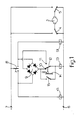
- the sliding/tilting roof 1 can be driven by means of an electromotor 2 which is connected to the sliding/tilting roof 1 through a schematically indicated coupling 3.
- the terminals of the electromotor 2 each are connectable to the negative pole 6 and the positive pole 7 of a voltage source not shown through a make-and-break contact 4 and 5, respectively.
- the make-and-break contacts 4 and 5 together form a pole reversing switch, through which the electromotor 2 can be connected to the voltage source for operation in a first or the opposite rotation direction.
- the make-and-break contacts 4 and 5 belong to relays 41 and 51, respectively, the excitation windings of which are directly connected to the negative pole 6 on the one side, whereas the other side of the excitation windings 41 and 51 can be connected to the positive pole 7 through a manually operable switch 8.
- the switch 8 has an open rest position determined by a spring not shown, the rest position being shown in fig. 1.
- the anode/cathode junctions of a diode bridge 9 are connected, while the two further junctions of the diode bridge 9 are connected to the contacts 10 and 11 of a switch 12, through which the excitation winding of an auxiliary relay 13 can be connected to said two junctions of the diode bridge 9.
- the other side of the excitation winding of the auxiliary relay 13 is directly connected to the negative pole 6.
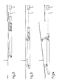
- the switch 12 is operable by a schematically shown control member 14 driven by the motor 2. In the position of the switch 12 shown in fig. 1, the sliding/tilting roof is in an open position.
- the auxiliary relay 13 has a make contact 15 connected in parallel to the contact 10 of the switch 12.
- the switch 8 is operated for exciting the excitation winding 51, whereby the make-and-break contact 5 connects the corresponding terminal of the motor 2 to the positive pole 7 and the other terminal remains connected to the negative pole 6 through the make-and-break contact 4.
- the motor now rotates in the reversed direction and moves the sliding/tilting roof 1 from the open position shown in fig. 2 to the closed position of fig. 3.
- switch 8 By actuating switch 8 a positive voltage is led to the contact 10 again through the corresponding anode/cathode junction of the diode bridge 9, so that the auxiliary relay 13 is excited and the make contact 15 is closed.
- the switch 8 is actuated for exciting the excitation winding 41.
- the contact arm of switch 12 will be switched over from contact 10 to contact 11, wherein the auxiliary relay 13 remains excited through the make contact 15 so that in this case relay 51 is excited by the positive voltage on contact 10, through the make contact 15, the switch 12 and the diode bridge 9.
- the invention provides a control device for a sliding/tilting roof, which is fully made with standard components so that the control device can be manufactured at relatively low costs.
- the manually operable switch 8 can be made as a single-pole switch which only has to carry the excitation currents for the relays 13, 41 and 51, so that this switch can be mounted within the reach of the driver of the motor vehicle without any objections.
- the connection wires to be connected to this switch may have a relatively small diameter, which results in a further reduction of the cost price.
- the used standard relays have a substantially noiseless operation so that they can be mounted near the sliding/tilting roof without any objections. Such standard relays moreover have a very reliable operation so that a failure free operation of the control device is guaranteed.
Landscapes
- Engineering & Computer Science (AREA)
- Power Engineering (AREA)
- Mechanical Engineering (AREA)
- Power-Operated Mechanisms For Wings (AREA)
Applications Claiming Priority (2)
| Application Number | Priority Date | Filing Date | Title |
|---|---|---|---|
| NL8700159A NL8700159A (nl) | 1987-01-23 | 1987-01-23 | Bedieningsinrichting voor een beweegbaar deel, bestemd voor het openen en sluiten van een opening, in het bijzonder een voertuigschuif/hefdak. |
| NL8700159 | 1987-01-23 |
Publications (2)
| Publication Number | Publication Date |
|---|---|
| EP0278536A1 true EP0278536A1 (de) | 1988-08-17 |
| EP0278536B1 EP0278536B1 (de) | 1991-05-02 |
Family
ID=19849459
Family Applications (1)
| Application Number | Title | Priority Date | Filing Date |
|---|---|---|---|
| EP88200017A Expired - Lifetime EP0278536B1 (de) | 1987-01-23 | 1988-01-08 | Kontrollvorrichtung zum Öffnen und Schliessen einer Öffnung, insbesondere eines Kraftfahrzeugschiebe-hebedaches |
Country Status (4)
| Country | Link |
|---|---|
| US (1) | US4841205A (de) |
| EP (1) | EP0278536B1 (de) |
| DE (1) | DE3862590D1 (de) |
| NL (1) | NL8700159A (de) |
Cited By (3)
| Publication number | Priority date | Publication date | Assignee | Title |
|---|---|---|---|---|
| EP0306950A3 (en) * | 1987-09-08 | 1990-04-04 | Webasto Ag Fahrzeugtechnik | Device for actuating movable parts for closing vehicle openings |
| EP0978402A1 (de) * | 1998-08-01 | 2000-02-09 | WEBASTO KAROSSERIESYSTEME GmbH | Vorrichtung zum Verstellen von bewegbaren Teilen an Fahrzeugen |
| EP0978401A1 (de) * | 1998-08-01 | 2000-02-09 | WEBASTO KAROSSERIESYSTEME GmbH | Vorrichtung zum Verstellen von bewegbaren Teilen an Fahrzeugen mittels eines kurzschliessbaren Stellmotors |
Families Citing this family (3)
| Publication number | Priority date | Publication date | Assignee | Title |
|---|---|---|---|---|
| US5098152A (en) * | 1989-12-26 | 1992-03-24 | Ohi Seisakusho Co., Ltd. | Automotive power sunroof |
| KR100534918B1 (ko) * | 2003-10-09 | 2005-12-08 | 현대자동차주식회사 | 전자석 제어를 통한 다중 접점 릴레이 |
| DE102004008394A1 (de) * | 2004-02-20 | 2005-09-08 | Siemens Ag | Vorrichtung und Verfahren zur Ansteuerung eines im Querzweig einer Brückenschaltung angeordneten Elektromotors |
Citations (5)
| Publication number | Priority date | Publication date | Assignee | Title |
|---|---|---|---|---|
| US3521136A (en) * | 1967-04-12 | 1970-07-21 | Jerry K Kelley | Control system for controlling speed and direction of rotation of two motors with a single main control member |
| DE2550991A1 (de) * | 1975-11-13 | 1977-05-18 | Audi Nsu Auto Union Ag | Vorrichtung zum betaetigen eines schiebe-hebedaches an kraftfahrzeugen |
| US4394605A (en) * | 1980-02-29 | 1983-07-19 | Nippondenso Co., Ltd. | Load drive control system |
| GB2147432A (en) * | 1983-09-28 | 1985-05-09 | Aisin Seiki | Controlling movement |
| FR2562736A1 (fr) * | 1984-04-05 | 1985-10-11 | Arnould Fabriq App Electr | Dispositif pour la commande de volet roulant ou analogue |
Family Cites Families (8)
| Publication number | Priority date | Publication date | Assignee | Title |
|---|---|---|---|---|
| FR2254146B1 (de) * | 1973-12-10 | 1977-09-30 | Amiens Const Elect Mec | |
| US4052625A (en) * | 1976-04-19 | 1977-10-04 | Cameron George L | Motor speed control circuit with overload protection |
| DE2704899A1 (de) * | 1977-02-05 | 1978-08-10 | Webasto Werk Baier Kg W | Betaetigungsvorrichtung fuer einen ausstellbaren schiebedeckel |
| FR2390849A1 (fr) * | 1977-05-12 | 1978-12-08 | Anvar | Commande de moteur electrique a courant continu, en particulier pour voiture electrique |
| US4260939A (en) * | 1978-08-07 | 1981-04-07 | Knauff Robert J | Low cost electromechanical electronic simulation circuits |
| DE2914864C2 (de) * | 1979-04-12 | 1983-08-25 | Rockwell Golde Gmbh, 6000 Frankfurt | Vorrichtung zum Betätigen eines einer Kraftfahrzeugdachöffnung zugeordneten Deckels |
| US4663537A (en) * | 1984-07-03 | 1987-05-05 | Keiper Recaro Gmbh & Co. | Protective circuit |
| US4617541A (en) * | 1985-09-16 | 1986-10-14 | Pen-Ho Huang | Electromagnetic starter for reversible motor |
-
1987
- 1987-01-23 NL NL8700159A patent/NL8700159A/nl not_active Application Discontinuation
-
1988
- 1988-01-08 DE DE8888200017T patent/DE3862590D1/de not_active Expired - Lifetime
- 1988-01-08 EP EP88200017A patent/EP0278536B1/de not_active Expired - Lifetime
- 1988-01-20 US US07/146,253 patent/US4841205A/en not_active Expired - Lifetime
Patent Citations (5)
| Publication number | Priority date | Publication date | Assignee | Title |
|---|---|---|---|---|
| US3521136A (en) * | 1967-04-12 | 1970-07-21 | Jerry K Kelley | Control system for controlling speed and direction of rotation of two motors with a single main control member |
| DE2550991A1 (de) * | 1975-11-13 | 1977-05-18 | Audi Nsu Auto Union Ag | Vorrichtung zum betaetigen eines schiebe-hebedaches an kraftfahrzeugen |
| US4394605A (en) * | 1980-02-29 | 1983-07-19 | Nippondenso Co., Ltd. | Load drive control system |
| GB2147432A (en) * | 1983-09-28 | 1985-05-09 | Aisin Seiki | Controlling movement |
| FR2562736A1 (fr) * | 1984-04-05 | 1985-10-11 | Arnould Fabriq App Electr | Dispositif pour la commande de volet roulant ou analogue |
Cited By (4)
| Publication number | Priority date | Publication date | Assignee | Title |
|---|---|---|---|---|
| EP0306950A3 (en) * | 1987-09-08 | 1990-04-04 | Webasto Ag Fahrzeugtechnik | Device for actuating movable parts for closing vehicle openings |
| EP0978402A1 (de) * | 1998-08-01 | 2000-02-09 | WEBASTO KAROSSERIESYSTEME GmbH | Vorrichtung zum Verstellen von bewegbaren Teilen an Fahrzeugen |
| EP0978401A1 (de) * | 1998-08-01 | 2000-02-09 | WEBASTO KAROSSERIESYSTEME GmbH | Vorrichtung zum Verstellen von bewegbaren Teilen an Fahrzeugen mittels eines kurzschliessbaren Stellmotors |
| US6369537B1 (en) | 1998-08-01 | 2002-04-09 | Webasto Karosseriesysteme Gmbh | Device for displacing movable parts on motor vehicles |
Also Published As
| Publication number | Publication date |
|---|---|
| DE3862590D1 (de) | 1991-06-06 |
| US4841205A (en) | 1989-06-20 |
| NL8700159A (nl) | 1988-08-16 |
| EP0278536B1 (de) | 1991-05-02 |
Similar Documents
| Publication | Publication Date | Title |
|---|---|---|
| EP0290106A2 (de) | Schiebedach-Kontrollapparat | |
| US6801109B2 (en) | Transfer switch including a circuit breaker housing | |
| US20030090849A1 (en) | Transfer switch including a circuit breaker housing | |
| EP0900905B1 (de) | Gerät zur Steuerung von elektrischen Fensterhebern | |
| US7046109B2 (en) | Multi-contact type relay by electromagnet | |
| EP0278536B1 (de) | Kontrollvorrichtung zum Öffnen und Schliessen einer Öffnung, insbesondere eines Kraftfahrzeugschiebe-hebedaches | |
| EP0310153B1 (de) | Bedienungsvorrichtung für ein Schiebe-Hebedach eines Kraftfahrzeuges | |
| US4727263A (en) | Electromotive setting device | |
| EP0147235A2 (de) | Scheibenwischerantriebsvorrichtung | |
| US4425535A (en) | Erroneous start preventing device for battery-powered vehicle | |
| JPH0727839Y2 (ja) | モータ駆動制御回路 | |
| JPH0212725A (ja) | 電磁リレー | |
| SU1594102A1 (ru) | Устройство дл управлени подвижным объектом | |
| JPH0793091B2 (ja) | 電磁リレー | |
| JPH0692290A (ja) | パワートリムアンドチルト機構制御装置 | |
| US20020109570A1 (en) | Electrical contactor with true status indication | |
| JPS6347924Y2 (de) | ||
| SU1625754A1 (ru) | Устройство дл контрол стрелочного привода | |
| JPH0212724A (ja) | 電磁リレー | |
| JPH0613345Y2 (ja) | ウインドレギユレ−タ | |
| JP3828638B2 (ja) | パワーウインドウの駆動回路 | |
| JP2964524B2 (ja) | ワイパー装置 | |
| JPS6057242B2 (ja) | 電動伸縮アンテナ駆動制御装置 | |
| JPH01315284A (ja) | 電磁リレー | |
| JPH0212723A (ja) | 電磁リレー |
Legal Events
| Date | Code | Title | Description |
|---|---|---|---|
| PUAI | Public reference made under article 153(3) epc to a published international application that has entered the european phase |
Free format text: ORIGINAL CODE: 0009012 |
|
| AK | Designated contracting states |
Kind code of ref document: A1 Designated state(s): DE FR GB IT NL SE |
|
| 17P | Request for examination filed |
Effective date: 19881230 |
|
| 17Q | First examination report despatched |
Effective date: 19900925 |
|
| GRAA | (expected) grant |
Free format text: ORIGINAL CODE: 0009210 |
|
| AK | Designated contracting states |
Kind code of ref document: B1 Designated state(s): DE FR GB IT NL SE |
|
| ITF | It: translation for a ep patent filed | ||
| REF | Corresponds to: |
Ref document number: 3862590 Country of ref document: DE Date of ref document: 19910606 |
|
| ET | Fr: translation filed | ||
| PLBE | No opposition filed within time limit |
Free format text: ORIGINAL CODE: 0009261 |
|
| STAA | Information on the status of an ep patent application or granted ep patent |
Free format text: STATUS: NO OPPOSITION FILED WITHIN TIME LIMIT |
|
| 26N | No opposition filed | ||
| EAL | Se: european patent in force in sweden |
Ref document number: 88200017.7 |
|
| REG | Reference to a national code |
Ref country code: GB Ref legal event code: IF02 |
|
| NLS | Nl: assignments of ep-patents |
Owner name: WEBASTOHOLLANDIA HOLDING B.V. |
|
| NLT1 | Nl: modifications of names registered in virtue of documents presented to the patent office pursuant to art. 16 a, paragraph 1 |
Owner name: WEBASTO PRODUCT INTERNATIONAL NL B.V. Owner name: WEBASTOHOLLANDIA OCTROOIEN B.V. |
|
| PGFP | Annual fee paid to national office [announced via postgrant information from national office to epo] |
Ref country code: FR Payment date: 20051226 Year of fee payment: 19 |
|
| PGFP | Annual fee paid to national office [announced via postgrant information from national office to epo] |
Ref country code: GB Payment date: 20060104 Year of fee payment: 19 |
|
| PGFP | Annual fee paid to national office [announced via postgrant information from national office to epo] |
Ref country code: SE Payment date: 20060118 Year of fee payment: 19 |
|
| PGFP | Annual fee paid to national office [announced via postgrant information from national office to epo] |
Ref country code: IT Payment date: 20060131 Year of fee payment: 19 Ref country code: NL Payment date: 20060131 Year of fee payment: 19 |
|
| PG25 | Lapsed in a contracting state [announced via postgrant information from national office to epo] |
Ref country code: SE Free format text: LAPSE BECAUSE OF NON-PAYMENT OF DUE FEES Effective date: 20070109 |
|
| PGFP | Annual fee paid to national office [announced via postgrant information from national office to epo] |
Ref country code: DE Payment date: 20070111 Year of fee payment: 20 |
|
| EUG | Se: european patent has lapsed | ||
| GBPC | Gb: european patent ceased through non-payment of renewal fee |
Effective date: 20070108 |
|
| NLV4 | Nl: lapsed or anulled due to non-payment of the annual fee |
Effective date: 20070801 |
|
| REG | Reference to a national code |
Ref country code: FR Ref legal event code: ST Effective date: 20070930 |
|
| PG25 | Lapsed in a contracting state [announced via postgrant information from national office to epo] |
Ref country code: GB Free format text: LAPSE BECAUSE OF NON-PAYMENT OF DUE FEES Effective date: 20070108 |
|
| PG25 | Lapsed in a contracting state [announced via postgrant information from national office to epo] |
Ref country code: NL Free format text: LAPSE BECAUSE OF NON-PAYMENT OF DUE FEES Effective date: 20070801 |
|
| PG25 | Lapsed in a contracting state [announced via postgrant information from national office to epo] |
Ref country code: FR Free format text: LAPSE BECAUSE OF NON-PAYMENT OF DUE FEES Effective date: 20070131 |
|
| PG25 | Lapsed in a contracting state [announced via postgrant information from national office to epo] |
Ref country code: IT Free format text: LAPSE BECAUSE OF NON-PAYMENT OF DUE FEES Effective date: 20070108 |