EP0278849A1 - Vorrichtung zum Mischen von fluiden Mitteln, insbesondere Flüssigkeiten, Abgabe der Mischung und Apparat mit einer solchen Vorrichtung - Google Patents
Vorrichtung zum Mischen von fluiden Mitteln, insbesondere Flüssigkeiten, Abgabe der Mischung und Apparat mit einer solchen Vorrichtung Download PDFInfo
- Publication number
- EP0278849A1 EP0278849A1 EP88400216A EP88400216A EP0278849A1 EP 0278849 A1 EP0278849 A1 EP 0278849A1 EP 88400216 A EP88400216 A EP 88400216A EP 88400216 A EP88400216 A EP 88400216A EP 0278849 A1 EP0278849 A1 EP 0278849A1
- Authority
- EP
- European Patent Office
- Prior art keywords
- mixing chamber
- support
- adjustment
- fluids
- bore
- Prior art date
- Legal status (The legal status is an assumption and is not a legal conclusion. Google has not performed a legal analysis and makes no representation as to the accuracy of the status listed.)
- Granted
Links
Images

Classifications
-
- B—PERFORMING OPERATIONS; TRANSPORTING
- B29—WORKING OF PLASTICS; WORKING OF SUBSTANCES IN A PLASTIC STATE IN GENERAL
- B29B—PREPARATION OR PRETREATMENT OF THE MATERIAL TO BE SHAPED; MAKING GRANULES OR PREFORMS; RECOVERY OF PLASTICS OR OTHER CONSTITUENTS OF WASTE MATERIAL CONTAINING PLASTICS
- B29B7/00—Mixing; Kneading
- B29B7/74—Mixing; Kneading using other mixers or combinations of mixers, e.g. of dissimilar mixers ; Plant
- B29B7/76—Mixers with stream-impingement mixing head
- B29B7/7663—Mixers with stream-impingement mixing head the mixing head having an outlet tube with a reciprocating plunger, e.g. with the jets impinging in the tube
- B29B7/7678—Mixers with stream-impingement mixing head the mixing head having an outlet tube with a reciprocating plunger, e.g. with the jets impinging in the tube of the gun type, i.e. hand-held units
Definitions
- the invention relates to a device for mixing fluids, in particular liquids, and for distributing the mixture thus produced.
- the invention is advantageously applicable for mixing and dispensing a mixture of chemically reactive liquid products, such as polyols or liquid organic resins with isocyanates to form polyurethane foam used for example for packaging.
- the US patents 4,023,733, 3,263,928 and French 2,122,920 describe such a device. wherein the mixing chamber comprises a Teflon core forming a mixing bore in which slides an adjustment rod to close or open the fluid intake conduits which open into the bore. Since this solution is not sufficient in itself, other additional provisions have been proposed to avoid blocking phenomena. Thus, it is known that it is advantageous to longitudinally offset the respective intake ducts of the fluids, to provide a solvent tank at the rear of the chamber, or to inject solvent or compressed air through the conduits and / or through the mixing chamber.
- the known devices in which the mixing chamber can be replaced are not satisfactory in practice because: .
- the replacement of the chamber requires the extraction of the rod from the support and its insertion in a new chamber which cannot generally be done without damaging the new core and the guide surfaces of the rod .
- the known embodiments of the removable association of the mixing chamber and / or of the rod with the support formed by the device and / or with the rod control means do not allow a sufficiently precise and centered association with respect to this. support and / or with respect to the control means, which generates rapid wear of the rod and the core, and generates the matching of the fluid supply conduits of the support of the device with those of the mixing chamber. .
- the means of removable association known from the mixing chamber to the support are not sufficiently resistant and manage to break before the complete plugging of the device and the replacement or cleaning of the mixing chamber, which can cause accidents and / or a complete deterioration of the device or its most expensive essential elements. .
- the mixing chambers, and especially the rods which slide in the core, are expensive and must be machined with great precision. It is therefore not desirable to have to systematically provide for several sets of mixing chambers and / or rods. .
- Disassembly and replacement manipulations are long and delicate to carry out, which affects productivity and can cause shocks, drops or soiling of the mixing chamber.
- the inventor has determined that in practice, the bore of the mixing chamber is only plugged very rarely since the rod drives out the products from this bore in the closed position, and that the plugging problems essentially remain only in the fluid supply conduits in the support and in the mixing chamber.
- the invention therefore has the general object of such a device which is more reliable and safer than in the prior art, which only becomes clogged very rarely and after very long use, and which is easy to maintain and safe.
- the essential aims of the invention are to remedy the drawbacks of known devices and to: . allow both easy and rapid cleaning of the fluid supply conduits of the support and of the mixing chamber, while avoiding and preventing any dissociation of the adjustment rod from its control means. . propose a device whose use and maintenance are more economical than for those of the prior art. . allow rapid, easy and precise reassembly of the mixing chamber on the support, the fluid supply conduits of the support being perfectly and automatically in correspondence with those of the mixing chamber, the mixing chamber being perfectly positioned relative to the adjustment means. . ensure a removable rigid association of the mixing chamber with the support more reliable and more resistant than in the prior art, in particular which resists even when the mixing chamber is completely blocked. . offer a device whose use and maintenance are absolutely safe and meet the most stringent safety standards.
- the invention proposes, according to a first essential characteristic, a device for mixing fluids, in particular liquids, and for distributing the mixture produced, comprising a support, a mixing chamber rigidly and removably associated with the support, mobile adjustment means in the mixing chamber for adjusting from the inside the flow rate of the fluids admitted into the mixing chamber - in particular making it possible to close or open the conduits for admitting the fluids into the mixing chamber -, and control means of the adjustment means, these control means being integral with the support, characterized in that the adjustment means are associated with the control means so as to be movable but not immediately separable from these control means, these adjustment means being also independent of the support, so that these adjustment means can be moved with the mixing chamber relative to the support, which allows t in particular the disengagement of the intake ducts and their cleaning without dissociation of the adjustment means relative to the control means.
- the device comprises two separate rods: an adjustment rod capable of sliding in an internal mixing bore of the mixing chamber and guided in its sliding by this mixing chamber to constitute the means for adjusting the flow rate of the fluids and a control rod integral with the control means, capable of sliding relative to the support and guided in its sliding by this support, to control the adjustment rod and the two rods are associated with each other in a mobile manner one compared to the other but not immediately dissociable from each other.
- an adjustment rod capable of sliding in an internal mixing bore of the mixing chamber and guided in its sliding by this mixing chamber to constitute the means for adjusting the flow rate of the fluids
- a control rod integral with the control means capable of sliding relative to the support and guided in its sliding by this support, to control the adjustment rod and the two rods are associated with each other in a mobile manner one compared to the other but not immediately dissociable from each other.
- the adjustment means of the control means are articulation means and the mixing chamber is associated with an external free surface of the support, so that it can be moved substantially perpendicular to this free surface when it is dissociated from the support.
- the invention also proposes, in a second essential characteristic, a device for mixing fluids, in particular liquids, and for distributing the mixture produced, comprising a support, a mixing chamber rigidly and removably associated with the support, at least one mobile adjusting member with axial sliding in the mixing chamber for adjusting the flow rate of the fluids admitted into the mixing chamber - in particular making it possible to close or open the ducts for admitting the fluids into the mixing chamber, characterized in that the removable rigid association means of the mixing chamber with the support comprise specific means of alignment and / or axial setting of the mixing chamber with respect to the support, so that the mixing chamber when it is associated with the support is and remains in a determined and precise position aligned with respect to the sliding axis of the adjusting member, and / or locked without possible axial play.
- the specific means of alignment and axial alignment may be constituted by respective and complementary shapes given to the external surface of the mixing chamber in contact with the support and to the surface of the support forming the housing of the mixing chamber and which is contact with the external surface of this chamber. It is for example at least one projection engaged in at least one groove.
- the mobile adjustment means are guided in their movements in the mixing chamber by guide means integral with and integrated into the mixing chamber to the exclusion of any other guidance relative to the support and / or to the control means.
- the invention also relates to a device for dispensing foam, in particular polyurethane foam, in particular for packaging or for other applications, and in particular manual, characterized in that it comprises a device according to the invention.
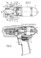
- a device for mixing fluids, in particular liquids, and for dispensing the mixture produced which comprises a support 1 in the general shape of a gun so that it can be easily manipulated.
- the support 1 therefore comprises a lower part 2 forming a grip handle, and an advanced part 3 in the general form of a barrel which supports a mixing chamber 4.
- the device also comprises means 5 for manual actuation, in particular in the form of a trigger, and which make it possible to actuate control means 6 mounted on the upper rear part 7 of the support 1.
- the actuation means 5 and the control means 6 are already known, in particular from US patents 4,023,733, 4,469,251, 3,263,928 and will not be described in detail.
- the control means 6 are advantageously formed by a double-acting pneumatic piston cylinder 8 supplied with compressed air by a rear inlet 9, the actuation means 5 comprising a valve controlling the actuation of the cylinder in one direction or in the other.
- Such a manual device is used according to the invention in a manual device for dispensing foam, in particular polyurethane foam for packaging, which also comprises independent fluid reservoirs, and means for supplying fluids under pressure from the device. .
- the invention is preferably intended for such a manual device, it is however also applicable for producing an automatic device such as that described in American patent 4 196 160, and which will then include a device according to the invention but for which the support 1 and the actuating means 5 will be adapted accordingly.
- the device is shown ready to operate, but not actuated.
- a device for mixing fluids, in particular liquids, and for distributing the mixture produced comprising a support 1, a mixing chamber 4 rigidly and removably associated with the support 1, means 11 adjustment valves in the mixing chamber 4 for adjusting from the inside the flow rate of the fluids admitted into the mixing chamber 4 - in particular making it possible to close or open the inlet conduits 12, 13 of the fluids in the mixing chamber 4 -, and means 6 for controlling the adjustment means 11, these control means 6 being integral with the support 1, is characterized in that the adjustment means 11 are associated with the control means 6 so as to be mobile but not immediately separable from these control means 6, these adjustment means 11 being by other means independent of the support 1, so that these adjustment means 11 can be moved with the mixing chamber 4 relative to the support 1, which allows in particular the release of the intake ducts 12, 13 and their cleaning without dissociation of the adjustment means 11 relative to the control means 6.
- not immediately separable is meant the fact that the adjustment means 11, although mounted to be movable relative to the control means 6, cannot be dissociated therefrom by the mere dissociation of the mixing chamber 4 from the support 1 without subsequent disassembly of at least one other element of the support 1 and / or the control means 6 or deterioration of a part of the device, for example means 14 for associating the adjustment means 11 with the control means 6.
- a device comprises two separate rods 11, 16: an adjustment rod 11 capable of sliding in an internal mixing bore 15 of the mixing chamber 4 and guided in its sliding by this mixing chamber 4 to constitute the means for adjusting the flow rate of the fluids and a control rod 16 integral with the control means 6, capable of sliding relative to the support 1 and guided in its sliding by this support 1, to control the adjustment rod 11 and the two rods 11, 16 are associated with each other so as to be movable relative to one another but not immediately separable from one another.
- the means 14 for mobile association of the adjustment means 11 with the control means 6 are articulation means and the mixing chamber 4 is associated with a free external surface 17 of the support 1, so that it can be moved substantially perpendicularly to this free surface 17 when it is dissociated from the support 1.
- the adjustment and control rods 11, 16 are articulated to one another by their free ends 18, 19 in particular by a ball joint or articulation 14 with clevis 20 and pin 21 or otherwise.
- the rods 11, 16 are substantially aligned with each other along an axis 22 when the mixing chamber 4 is associated with the support 1 and when they are in the operating position.
- the means 14 for associating the rods 11, 16 with one another comprise an articulation makes it possible to compensate for the misalignment of the rods 11, 16, one with respect to the other, in particular due to misalignment of the mixing chamber 4 relative to the axis 22 of sliding in translation of the control rod 16 secured to the piston 8. As a result, the lifetime of the mixture 4 and the adjusting rod 11 is increased.
- the common axis 22 is also the axis of sliding of the rods 11, 16 moved in translation when the means 5 for activating are actuated.
- the adjusting rod 11 enters the mixture bore 15 through the end 24 of this bore 15 opposite that 25 forming a dispensing orifice for the mixture produced and the intake ducts 12, 13 open onto the internal surface 26 of the mix bore 15 ( Figure 4).
- the mixing chamber 4 is placed on an external free surface 17 of the advanced part 3 of the support 1, and is rigidly but removably associated with this support 1 by means of a screw 27 engaged from below in a bore 28 of the support 1 perpendicular to the sliding axis 22 and crimped in this bore 28.
- the threaded part 29 of this screw 27 opens upwards and projects from the free surface 17 to penetrate a tapping 30 formed in the casing 31 of the mixing chamber 4.
- the supply pipes (not shown) for fluids to the device can be connected on each side of the support 1 to the intakes 32, 33 which supply by valves 34, 35 known per se (for example from French patent 2,511,889) the conduits of 'leads 36, 37 of the support 1, extended by the intake ducts 12, 13 of the mixing chamber 4 (FIG. 4) which open into the mixing bore 15.
- the control rod 16 is associated with and integral in its movements with the piston 8, for example by means of association with circlips and groove. It passes through this piston 8 on the rear and has an extension 38, opposite its free end 16 of association with the adjustment rod 11.
- the extension 38 passes through the chamber 39 of the control cylinder and slides in a rear bore 40 formed in the rear cover 41 of the support 1.
- the rear bore 40 is parallel to the axis 22 and makes it possible to guide, with a range 42 of the support 1 through which the control rod 16 passes, and the bearing surface 43 of the piston 8 on the walls of chamber 39, the control rod 16 and piston 8 assembly in its movements.
- At least one groove 44 (preferably two diametrically opposite grooves) extending parallel to the axis 22 is formed in the rear bore 40.
- the piston 8 When the trigger 5 is actuated, the piston 8 is moved backwards, driving the control rod 16 then the adjustment rod 11 associated therewith.
- the ducts 12, 13 for admission into the bore 15 are then uncovered, which allows the mixing of the fluids in this bore 15 and the distribution of the mixture under pressure through the orifice 25.
- the rod 11 of adjustment covers the conduits 12, 13 and drives the excess mixture out of the bore 15.
- conduits 12, 13 for admitting fluids from the mixing chamber 4 or the conduits 36, 37 for supplying the support 1 become blocked, it is possible to unblock them as follows: the upper cover 23 is removed, the screw 27 is unscrewed to release the mixing chamber 4, and the mixing chamber 4 and adjusting rod 11 assembly is pivoted around the articulation 14, upwards, in order to access the conduits 12, 13, 36, 37 respectively of the mixing chamber 4 and of the support 1. It is then possible to simply unblock these conduits (by means of a solvent, compressed air, etc.). The mixing chamber 4 is then replaced on the free surface 17 of the support 1 by pivoting the assembly 4, 11 downward and by screwing the screw 27 back into the thread 30.
- the screw 27 is advantageously automatically placed relative to the support 1 when it is tightened, thanks to the shape of its bearing surfaces on the support 1, so that it correctly angularly positions the mixing chamber 4 around the axis 22, the conduits 36, 37 of the support, and 12, 13 of admission of the chamber 4 communicating with each other.
- Seals 49, 50 preferably secured to the support 1 are advantageously interposed between the conduits 36, 37 of the support 1 and those 12, 13 of the chamber 4.
- the articulation 14 of the adjustment rod 11 relative to the control rod 16 must therefore be such that it allows pivoting perpendicular to the free surface 17 upwards of the chamber 4 and adjustment rod 11 assembly.
- This articulation 14 advantageously and preferably consists of a yoke 20 of the free end 19 of the control rod 16, the groove of which is substantially vertical (assuming the gun is held vertically), and the wings of which are provided with holes for the passage of a pin 21.
- the free end 18 of the adjustment rod 11 is engaged in the groove of the yoke 20, and is also provided with a passage for the passage of the pin 21.
- these holes may have a dimension greater than that strictly necessary for the single passage of the pin 21, in particular having an oblong shape in the vertical direction.
- the means of association of the mixing chamber 4 with the support 1 are arranged so as to allow any misalignment to be made up, and in particular these association means allow a certain relative friction of the mixture 4 relative to the support 1.
- Safety means can be provided to prevent any untimely disengagement of the pin 21 from the yoke 20.
- the pin 21 in the horizontal position cannot be easily removed from the yoke 20.
- the pin 21 preferably provides that the pin 21 has a length such that its horizontal release from the yoke 20 is made impossible by the substantially vertical side walls 46, 47 of the support which extend axially.
- the rear cover 41 When it is desired to dissociate the adjustment rod 11 from the control rod 16 and dismantle the articulation 14, the rear cover 41 is dismantled, which releases the pin 48 from the grooves 44, and allows rotation of the rod 16 by control around its axis 22.
- the pin 21 of the joint 14 is thus placed in a vertical position and to drive it vertically upwards. To reassemble the joint, the reverse operations are carried out.
- conduits 12, 13 36, 37 of the support 1 and of the chamber 4 are not perfectly aligned with each other respectively, especially longitudinally, which must be absolutely avoided.
- the inventor has determined that an axial setting and perfect alignment of the mixing chamber 4 considerably increase the life of this chamber 4, and above all the times of use without clogging.
- the invention also proposes, according to a second aspect, a device for mixing fluids, in particular liquids, and for distributing the mixture produced, comprising a support 1, a mixing chamber 4 rigidly and removably associated with the sup port 1, at least one movable adjustment member 11 with axial sliding in the mixing chamber 4 for adjusting the flow rate of the fluids admitted into the mixing chamber 4, - in particular enabling the conduits 12, 13 to be closed or opened admission of fluids into the mixing chamber 4 -, characterized in that the removable rigid association means of the mixing chamber 4 with the support 1 comprise specific means 51, 52 for alignment and / or axial setting of the chamber of mixing 4 relative to the support 1 so that the mixing chamber 4, when associated with the support 1, is and remains in a determined and precise position aligned with respect to the sliding axis 22 of the member 11 adjustment and / or stalled without axial play possible.
- the specific means 51, 52 for axial alignment and wedging consist of the respective and complementary shapes given to the external surface 53 of the mixing chamber 4 in contact with the support 1 and to the surface 17 of the support 1 forming housing of the mixing chamber 4 and which is in contact with the external surface 53 of this chamber 4.
- the specific means 51, 52 for alignment and / or axial setting comprise at least one projection 51 - in particular at least one rib 51 projecting from the free surface 17 of the support 1 -, engaged in at least one groove 52 - in particular in the hollow of the external surface 53 of the mixing chamber 4-.
- the projections 51 and groove 52 extend in a plane perpendicular to the sliding axis 22.
- the specific means 51, 52 for axial alignment and / or wedging comprise at least one rib projecting from the mixing chamber 4 and at least one groove in the support 1.
- the external surface 53 of the mixing chamber 4 is cylindrical or pseudo-cylindrical and the support 1 has a surface 17 defining a hollow housing for the mixing chamber 4, of a shape complementary to that of the external surface 53, and the specific means 51, 52 for alignment and / or axial wedge extend in a transverse plane over at least a peripheral part of the surfaces 53, 17 cylindrical or pseudo-cylindrical in contact.
- a projection 51 and a groove 52 of the specific means of alignment and / or axial setting have, in cross-section, substantially a U-shape whose wings 54, 55 diverge outwards from the core 56. In this way, the timing and alignment - axial are better ensured, and the release of the projection 51 out of the groove 52 does not pose any problems, in particular during the pivoting of the chamber 4 around the articulation 14 of the adjustment rod 11 and control rod 16.
- the mixing chamber 4 extends in the axial direction of sliding of the adjusting member 11, has a central bore 15 in which the adjusting member 11 is capable of sliding when penetrating through one end 24 of this bore 15, and a dispensing orifice 25 constituted by the opposite end of bore 15, and the specific means 51, 52 for alignment and / or axial setting are located in the vicinity of part 57 of the mixing chamber 4 axially opposite the dispensing orifice 25. ( Figures 1 and 2).
- a flat 58 is formed on the upper part of the chamber 4, over its entire length.
- the upper protective cover 23 bears on the front of this flat 58.
- the movable adjustment means 11 are guided in their movements in the mixing chamber 4 by guide means 59 integral with and integrated into the mixing chamber 4 to the exclusion of any other guidance relative to the support 1 and / or to the control means 6.
- the guide means 59 consist for example of a nut screwed to the rear of the casing 31 of the chamber 4, pierced with a bore 61 traversed by the rod 11 which carries on this bore 61 a seal 60 to the rear of and held against the bore 61 by a washer 62 and a circlip 63.
- the mixing chamber 4 comprises a core of Teflon® 64 or of similar material through which a bore 15 is produced, this core 64 being inserted in a casing 31, and, in the vicinity of the dispensing orifice 25, the core 64 is flush with, or protrudes from, the casing 31 so that the distributed mixture cannot accumulate on the casing 31 around the orifice 25 (FIG. 2).
- the mixing chamber 4 comprises elastic means 65 for compressing the core 64 of the cable gland type, and the core 64 comprises a retaining shoulder 66 in the vicinity of the orifice 25, this shoulder 66 cooperating with a flange 67 of the casing 31 to prevent the untimely exit of the core 64 from the casing 31.
- the nut of the guide means 59 cooperating with a tapping of the casing 31 compresses elastic washers and the core 64 in the casing 31 against the flange 67, which forms a cable gland.
- the specific means 51, 52 for alignment and / or axial setting have a shape such that they can be dissociated by pivoting of the mixing chamber 4 dissociated from the support 1 and means 11 for adjusting around their articulation 14 with the control means 6.
- the projection 51 and the groove 52 are curved in a circle substantially centered on the pivot joint 14.
Landscapes
- Engineering & Computer Science (AREA)
- Mechanical Engineering (AREA)
- Accessories For Mixers (AREA)
- Processing And Handling Of Plastics And Other Materials For Molding In General (AREA)
- Nozzles (AREA)
- Multiple-Way Valves (AREA)
Priority Applications (1)
| Application Number | Priority Date | Filing Date | Title |
|---|---|---|---|
| AT88400216T ATE52057T1 (de) | 1987-01-30 | 1988-01-29 | Vorrichtung zum mischen von fluiden mitteln, insbesondere fluessigkeiten, abgabe der mischung und apparat mit einer solchen vorrichtung. |
Applications Claiming Priority (2)
| Application Number | Priority Date | Filing Date | Title |
|---|---|---|---|
| FR8701117 | 1987-01-30 | ||
| FR8701117A FR2610216B1 (fr) | 1987-01-30 | 1987-01-30 | Dispositif de melange de fluides, notamment de liquides, et distribution du melange ainsi realise et appareil comportant un tel dispositif |
Publications (2)
| Publication Number | Publication Date |
|---|---|
| EP0278849A1 true EP0278849A1 (de) | 1988-08-17 |
| EP0278849B1 EP0278849B1 (de) | 1990-04-18 |
Family
ID=9347425
Family Applications (1)
| Application Number | Title | Priority Date | Filing Date |
|---|---|---|---|
| EP88400216A Expired - Lifetime EP0278849B1 (de) | 1987-01-30 | 1988-01-29 | Vorrichtung zum Mischen von fluiden Mitteln, insbesondere Flüssigkeiten, Abgabe der Mischung und Apparat mit einer solchen Vorrichtung |
Country Status (8)
| Country | Link |
|---|---|
| US (1) | US4860925A (de) |
| EP (1) | EP0278849B1 (de) |
| JP (1) | JPS6422330A (de) |
| AT (1) | ATE52057T1 (de) |
| AU (1) | AU599543B2 (de) |
| CA (1) | CA1338312C (de) |
| DE (1) | DE3860089D1 (de) |
| FR (1) | FR2610216B1 (de) |
Cited By (2)
| Publication number | Priority date | Publication date | Assignee | Title |
|---|---|---|---|---|
| WO1991003362A1 (fr) * | 1989-09-08 | 1991-03-21 | Freddy Delphin Soudan | Appareil doseur de mousse de polyurethane |
| US5265761A (en) * | 1992-07-10 | 1993-11-30 | Insta-Foam Products, Inc. | High performance foam dispensing gun |
Families Citing this family (10)
| Publication number | Priority date | Publication date | Assignee | Title |
|---|---|---|---|---|
| US5270013A (en) * | 1992-05-06 | 1993-12-14 | Decker Herman W | Reactive fluid mixing head |
| US7156260B2 (en) | 2003-05-09 | 2007-01-02 | Intellipack | Mixing module drive mechanism and dispensing system with same |
| US7386969B2 (en) * | 2003-05-09 | 2008-06-17 | Intellipack | Exterior configuration of a foam-in-bag dispenser assembly |
| DE602004017181D1 (de) * | 2003-05-09 | 2008-11-27 | Intellipack Inc | Abgabesystem mit mischmodulhalterung |
| DE602004009058T2 (de) * | 2003-05-09 | 2008-05-08 | IntelliPack, Inc., Tulsa | Mischspender-modul und verfahren für dessen zusammenbau und seiner verwendung |
| US7552847B2 (en) * | 2003-05-09 | 2009-06-30 | Intellipack | Dispenser mixing module and method of assembling and using same |
| US7182221B2 (en) * | 2003-05-09 | 2007-02-27 | Intellipack | Dispensing system and method of manufacturing and using same with a dispenser tip management |
| CA2773627C (en) | 2009-09-15 | 2018-01-02 | Solvay Sa | Process for treating with a chemical compound a body of water used in aquaculture |
| US20120279991A1 (en) * | 2009-12-08 | 2012-11-08 | Graco Minnesota Inc. | Tool-less quick-change valving rod |
| EP3810313A4 (de) * | 2018-06-21 | 2022-04-13 | Silgan Dispensing Systems Corporation | Abgabeanordnung mit einer vorrichtung zum mischen von additiven |
Citations (1)
| Publication number | Priority date | Publication date | Assignee | Title |
|---|---|---|---|---|
| US4133483A (en) * | 1977-07-05 | 1979-01-09 | Binks Manufacturing Company | Plural component gun |
Family Cites Families (5)
| Publication number | Priority date | Publication date | Assignee | Title |
|---|---|---|---|---|
| US3784110A (en) * | 1972-11-16 | 1974-01-08 | W Brooks | Mixing and dispensing gun having a replaceable nozzle |
| IT1115643B (it) * | 1977-04-07 | 1986-02-03 | Afros Srl | Apparecchiatura per la miscelazione e l'eifzione di sostanze shiumogene |
| US4568003A (en) * | 1981-09-02 | 1986-02-04 | Sealed Air Corporation | Detachable mixing chamber for a fluid dispensing apparatus |
| US4993596A (en) * | 1985-05-10 | 1991-02-19 | Insta-Foam Products Inc. | Mixing and dispensing gun with improved removal nozzle |
| US4708292A (en) * | 1985-06-05 | 1987-11-24 | Olin Corporation | Foam dispensing gun with improved mixing chamber |
-
1987
- 1987-01-30 FR FR8701117A patent/FR2610216B1/fr not_active Expired
-
1988
- 1988-01-25 US US07/149,918 patent/US4860925A/en not_active Expired - Lifetime
- 1988-01-29 AU AU10973/88A patent/AU599543B2/en not_active Ceased
- 1988-01-29 DE DE8888400216T patent/DE3860089D1/de not_active Expired - Lifetime
- 1988-01-29 EP EP88400216A patent/EP0278849B1/de not_active Expired - Lifetime
- 1988-01-29 AT AT88400216T patent/ATE52057T1/de not_active IP Right Cessation
- 1988-01-29 CA CA000557748A patent/CA1338312C/fr not_active Expired - Fee Related
- 1988-01-29 JP JP63017549A patent/JPS6422330A/ja active Pending
Patent Citations (1)
| Publication number | Priority date | Publication date | Assignee | Title |
|---|---|---|---|---|
| US4133483A (en) * | 1977-07-05 | 1979-01-09 | Binks Manufacturing Company | Plural component gun |
Cited By (4)
| Publication number | Priority date | Publication date | Assignee | Title |
|---|---|---|---|---|
| WO1991003362A1 (fr) * | 1989-09-08 | 1991-03-21 | Freddy Delphin Soudan | Appareil doseur de mousse de polyurethane |
| BE1003547A3 (fr) * | 1989-09-08 | 1992-04-21 | Soudan Freddy Delphin | Appareil doseur de mousse de polyurethane. |
| US5375743A (en) * | 1989-09-08 | 1994-12-27 | Soudan; Freddy D. | Polyurethane foam metering apparatus |
| US5265761A (en) * | 1992-07-10 | 1993-11-30 | Insta-Foam Products, Inc. | High performance foam dispensing gun |
Also Published As
| Publication number | Publication date |
|---|---|
| EP0278849B1 (de) | 1990-04-18 |
| ATE52057T1 (de) | 1990-05-15 |
| DE3860089D1 (de) | 1990-05-23 |
| FR2610216B1 (fr) | 1989-06-09 |
| US4860925A (en) | 1989-08-29 |
| CA1338312C (fr) | 1996-05-07 |
| AU599543B2 (en) | 1990-07-19 |
| JPS6422330A (en) | 1989-01-25 |
| AU1097388A (en) | 1988-08-04 |
| FR2610216A1 (fr) | 1988-08-05 |
Similar Documents
| Publication | Publication Date | Title |
|---|---|---|
| EP0278849B1 (de) | Vorrichtung zum Mischen von fluiden Mitteln, insbesondere Flüssigkeiten, Abgabe der Mischung und Apparat mit einer solchen Vorrichtung | |
| CH650941A5 (fr) | Appareil distributeur de fluide et chambre de melange pour cet appareil. | |
| BE1003547A3 (fr) | Appareil doseur de mousse de polyurethane. | |
| FR2688197A1 (fr) | Fermeture distributrice a collier de basculement. | |
| WO2008007000A2 (fr) | Systeme d'injection de fluide cryogenique permettant le traitement de produits en vrac et procede de refroidissement le mettant en oeuvre | |
| EP2021664A1 (de) | Ventil | |
| FR2657143A1 (fr) | Raccord rapide sans fuite de fluide. | |
| EP3785802A1 (de) | Ventil, system zur auftragung eines beschichtungsprodukts, das ein solches ventil umfasst, und werkzeug für dessen montage und demontage | |
| EP3742037B1 (de) | Anschlussbuchse eines fluidanschlusses, untereinheit zum anschliessen und anschluss, der eine solche anschlussbuchse umfasst | |
| CA2636627C (fr) | Machine hydraulique, en particulier moteur hydraulique, a mouvement alternatif | |
| FR2519266A1 (fr) | Dispositif de melange et de distribution par doses d'un produit et application pour la distribution de colles, notamment a base de resine epoxyde | |
| FR2901340A1 (fr) | Agencement de distributeur hydraulique sous forme de cartouche | |
| CA2522938A1 (fr) | Distributeur d`echantillon cosmetique mono-dose | |
| FR2498729A1 (fr) | Raccord pour tuyaux | |
| FR2933320A1 (fr) | Dispositif d'application de peinture et procede de nettoyage d'un tel dispositif | |
| FR2878313A1 (fr) | Ensemble de distribution et de remplissage controle d'une bouteille de gaz sous pression | |
| EP1468147A1 (de) | Brauseschlauch mit einem zweiwegeventil und zweiwegenventil für brauseschlauch | |
| CA3001049A1 (fr) | Machine hydraulique et pompe doseuse reversible equipee d'une telle machine | |
| FR2785817A1 (fr) | Robinet et extincteur portable a pression permanente equipe d'un tel robinet | |
| EP1683580B1 (de) | Sprüh-Beschichtungspistole für Baustoff | |
| FR2524107A1 (fr) | Mecanisme de manoeuvre d'une soupape | |
| BE1009300A3 (fr) | Raccord pour tuyaux destines au passage de fluides sous pression. | |
| EP1971775B1 (de) | Hydraulische maschine, insbesondere hydromotor, mit einer hubbewegung und differenzialkolben für solch eine maschine | |
| FR2638503A1 (fr) | Vanne a disques a manchon de decharge amovible pour l'ecoulement d'un fluide | |
| EP1647419B1 (de) | Austragsdüse für körniges Material |
Legal Events
| Date | Code | Title | Description |
|---|---|---|---|
| PUAI | Public reference made under article 153(3) epc to a published international application that has entered the european phase |
Free format text: ORIGINAL CODE: 0009012 |
|
| 17P | Request for examination filed |
Effective date: 19880402 |
|
| AK | Designated contracting states |
Kind code of ref document: A1 Designated state(s): AT BE CH DE ES FR GB GR IT LI LU NL SE |
|
| 17Q | First examination report despatched |
Effective date: 19890615 |
|
| GRAA | (expected) grant |
Free format text: ORIGINAL CODE: 0009210 |
|
| AK | Designated contracting states |
Kind code of ref document: B1 Designated state(s): AT BE CH DE ES FR GB GR IT LI LU NL SE |
|
| PG25 | Lapsed in a contracting state [announced via postgrant information from national office to epo] |
Ref country code: GR Free format text: LAPSE BECAUSE OF FAILURE TO SUBMIT A TRANSLATION OF THE DESCRIPTION OR TO PAY THE FEE WITHIN THE PRESCRIBED TIME-LIMIT Effective date: 19900418 Ref country code: NL Effective date: 19900418 Ref country code: GB Effective date: 19900418 Ref country code: ES Free format text: THE PATENT HAS BEEN ANNULLED BY A DECISION OF A NATIONAL AUTHORITY Effective date: 19900418 Ref country code: AT Effective date: 19900418 Ref country code: IT Free format text: LAPSE BECAUSE OF FAILURE TO SUBMIT A TRANSLATION OF THE DESCRIPTION OR TO PAY THE FEE WITHIN THE PRE;WARNING: LAPSES OF ITALIAN PATENTS WITH EFFECTIVE DATE BEFORE 2007 MAY HAVE OCCURRED AT ANY TIME BEFORE 2007. THE CORRECT EFFECTIVE DATE MAY BE DIFFERENT FROM THE ONE RECORDED.SCRIBED TIME-LIMIT Effective date: 19900418 Ref country code: SE Effective date: 19900418 |
|
| REF | Corresponds to: |
Ref document number: 52057 Country of ref document: AT Date of ref document: 19900515 Kind code of ref document: T |
|
| REF | Corresponds to: |
Ref document number: 3860089 Country of ref document: DE Date of ref document: 19900523 |
|
| NLV1 | Nl: lapsed or annulled due to failure to fulfill the requirements of art. 29p and 29m of the patents act | ||
| GBV | Gb: ep patent (uk) treated as always having been void in accordance with gb section 77(7)/1977 [no translation filed] | ||
| PG25 | Lapsed in a contracting state [announced via postgrant information from national office to epo] |
Ref country code: LU Free format text: LAPSE BECAUSE OF NON-PAYMENT OF DUE FEES Effective date: 19910131 |
|
| PLBE | No opposition filed within time limit |
Free format text: ORIGINAL CODE: 0009261 |
|
| STAA | Information on the status of an ep patent application or granted ep patent |
Free format text: STATUS: NO OPPOSITION FILED WITHIN TIME LIMIT |
|
| 26N | No opposition filed | ||
| PGFP | Annual fee paid to national office [announced via postgrant information from national office to epo] |
Ref country code: FR Payment date: 19990115 Year of fee payment: 12 |
|
| REG | Reference to a national code |
Ref country code: FR Ref legal event code: TP |
|
| PGFP | Annual fee paid to national office [announced via postgrant information from national office to epo] |
Ref country code: CH Payment date: 20000724 Year of fee payment: 13 |
|
| PGFP | Annual fee paid to national office [announced via postgrant information from national office to epo] |
Ref country code: BE Payment date: 20000727 Year of fee payment: 13 |
|
| PG25 | Lapsed in a contracting state [announced via postgrant information from national office to epo] |
Ref country code: FR Free format text: LAPSE BECAUSE OF NON-PAYMENT OF DUE FEES Effective date: 20000929 |
|
| REG | Reference to a national code |
Ref country code: FR Ref legal event code: ST |
|
| REG | Reference to a national code |
Ref country code: CH Ref legal event code: NV Representative=s name: MICHELI & CIE INGENIEURS-CONSEILS Ref country code: CH Ref legal event code: PFA Free format text: COMPTOIR GENERAL D'EMBALLAGE (SA),84 A 94, RUE LOUIS BECKER,VILLEURBANNE (FR) TRANSFER- COMPTOIR GENERAL D'EMBALLAGE (SA),15, RUE EMILE DECORPS,69100 VILLEURBANNE (FR) Ref country code: CH Ref legal event code: PUE Owner name: COMPTOIR GENERAL D'EMBALLAGE (SA) TRANSFER- SEALED |
|
| BECA | Be: change of holder's address |
Free format text: 20001011 *SEALED AIR CORP.:PARK 80 EAST, SADDLE BROOK NEW JERSEY 07663 |
|
| PG25 | Lapsed in a contracting state [announced via postgrant information from national office to epo] |
Ref country code: LI Free format text: LAPSE BECAUSE OF NON-PAYMENT OF DUE FEES Effective date: 20010131 Ref country code: BE Free format text: LAPSE BECAUSE OF NON-PAYMENT OF DUE FEES Effective date: 20010131 Ref country code: CH Free format text: LAPSE BECAUSE OF NON-PAYMENT OF DUE FEES Effective date: 20010131 |
|
| BERE | Be: lapsed |
Owner name: SEALED AIR CORP. Effective date: 20010131 |
|
| REG | Reference to a national code |
Ref country code: CH Ref legal event code: PL |
|
| PGFP | Annual fee paid to national office [announced via postgrant information from national office to epo] |
Ref country code: DE Payment date: 20040205 Year of fee payment: 17 |
|
| PG25 | Lapsed in a contracting state [announced via postgrant information from national office to epo] |
Ref country code: DE Free format text: LAPSE BECAUSE OF NON-PAYMENT OF DUE FEES Effective date: 20050802 |