EP0278920B1 - Fernbedienungsgerät für die Auslösung von Schaltern - Google Patents
Fernbedienungsgerät für die Auslösung von Schaltern Download PDFInfo
- Publication number
- EP0278920B1 EP0278920B1 EP88830037A EP88830037A EP0278920B1 EP 0278920 B1 EP0278920 B1 EP 0278920B1 EP 88830037 A EP88830037 A EP 88830037A EP 88830037 A EP88830037 A EP 88830037A EP 0278920 B1 EP0278920 B1 EP 0278920B1
- Authority
- EP
- European Patent Office
- Prior art keywords
- switch
- additional
- contacting means
- coil
- contacts
- Prior art date
- Legal status (The legal status is an assumption and is not a legal conclusion. Google has not performed a legal analysis and makes no representation as to the accuracy of the status listed.)
- Expired - Lifetime
Links
Images


Classifications
-
- H—ELECTRICITY
- H01—ELECTRIC ELEMENTS
- H01H—ELECTRIC SWITCHES; RELAYS; SELECTORS; EMERGENCY PROTECTIVE DEVICES
- H01H83/00—Protective switches, e.g. circuit-breaking switches, or protective relays operated by abnormal electrical conditions otherwise than solely by excess current
- H01H83/20—Protective switches, e.g. circuit-breaking switches, or protective relays operated by abnormal electrical conditions otherwise than solely by excess current operated by excess current as well as by some other abnormal electrical condition
-
- H—ELECTRICITY
- H02—GENERATION; CONVERSION OR DISTRIBUTION OF ELECTRIC POWER
- H02J—ELECTRIC POWER NETWORKS; CIRCUIT ARRANGEMENTS OR SYSTEMS FOR SUPPLYING OR DISTRIBUTING ELECTRIC POWER; SYSTEMS FOR STORING ELECTRIC ENERGY
- H02J13/00—Circuit arrangements for providing remote monitoring or remote control of equipment in a power distribution network
- H02J13/13—Circuit arrangements for providing remote monitoring or remote control of equipment in a power distribution network characterised by the transmission of data to equipment in the power network
-
- H—ELECTRICITY
- H02—GENERATION; CONVERSION OR DISTRIBUTION OF ELECTRIC POWER
- H02J—ELECTRIC POWER NETWORKS; CIRCUIT ARRANGEMENTS OR SYSTEMS FOR SUPPLYING OR DISTRIBUTING ELECTRIC POWER; SYSTEMS FOR STORING ELECTRIC ENERGY
- H02J13/00—Circuit arrangements for providing remote monitoring or remote control of equipment in a power distribution network
- H02J13/18—Circuit arrangements for providing remote monitoring or remote control of equipment in a power distribution network characterised by the remotely-controlled equipment, e.g. converters or transformers
- H02J13/34—Circuit arrangements for providing remote monitoring or remote control of equipment in a power distribution network characterised by the remotely-controlled equipment, e.g. converters or transformers the equipment being switches, relays or circuit breakers
-
- Y—GENERAL TAGGING OF NEW TECHNOLOGICAL DEVELOPMENTS; GENERAL TAGGING OF CROSS-SECTIONAL TECHNOLOGIES SPANNING OVER SEVERAL SECTIONS OF THE IPC; TECHNICAL SUBJECTS COVERED BY FORMER USPC CROSS-REFERENCE ART COLLECTIONS [XRACs] AND DIGESTS
- Y02—TECHNOLOGIES OR APPLICATIONS FOR MITIGATION OR ADAPTATION AGAINST CLIMATE CHANGE
- Y02B—CLIMATE CHANGE MITIGATION TECHNOLOGIES RELATED TO BUILDINGS, e.g. HOUSING, HOUSE APPLIANCES OR RELATED END-USER APPLICATIONS
- Y02B70/00—Technologies for an efficient end-user side electric power management and consumption
- Y02B70/30—Systems integrating technologies related to power network operation and communication or information technologies for improving the carbon footprint of the management of residential or tertiary loads, i.e. smart grids as climate change mitigation technology in the buildings sector, including also the last stages of power distribution and the control, monitoring or operating management systems at local level
-
- Y—GENERAL TAGGING OF NEW TECHNOLOGICAL DEVELOPMENTS; GENERAL TAGGING OF CROSS-SECTIONAL TECHNOLOGIES SPANNING OVER SEVERAL SECTIONS OF THE IPC; TECHNICAL SUBJECTS COVERED BY FORMER USPC CROSS-REFERENCE ART COLLECTIONS [XRACs] AND DIGESTS
- Y02—TECHNOLOGIES OR APPLICATIONS FOR MITIGATION OR ADAPTATION AGAINST CLIMATE CHANGE
- Y02B—CLIMATE CHANGE MITIGATION TECHNOLOGIES RELATED TO BUILDINGS, e.g. HOUSING, HOUSE APPLIANCES OR RELATED END-USER APPLICATIONS
- Y02B90/00—Enabling technologies or technologies with a potential or indirect contribution to GHG emissions mitigation
- Y02B90/20—Smart grids as enabling technology in buildings sector
-
- Y—GENERAL TAGGING OF NEW TECHNOLOGICAL DEVELOPMENTS; GENERAL TAGGING OF CROSS-SECTIONAL TECHNOLOGIES SPANNING OVER SEVERAL SECTIONS OF THE IPC; TECHNICAL SUBJECTS COVERED BY FORMER USPC CROSS-REFERENCE ART COLLECTIONS [XRACs] AND DIGESTS
- Y02—TECHNOLOGIES OR APPLICATIONS FOR MITIGATION OR ADAPTATION AGAINST CLIMATE CHANGE
- Y02E—REDUCTION OF GREENHOUSE GAS [GHG] EMISSIONS, RELATED TO ENERGY GENERATION, TRANSMISSION OR DISTRIBUTION
- Y02E60/00—Enabling technologies; Technologies with a potential or indirect contribution to GHG emissions mitigation
-
- Y—GENERAL TAGGING OF NEW TECHNOLOGICAL DEVELOPMENTS; GENERAL TAGGING OF CROSS-SECTIONAL TECHNOLOGIES SPANNING OVER SEVERAL SECTIONS OF THE IPC; TECHNICAL SUBJECTS COVERED BY FORMER USPC CROSS-REFERENCE ART COLLECTIONS [XRACs] AND DIGESTS
- Y04—INFORMATION OR COMMUNICATION TECHNOLOGIES HAVING AN IMPACT ON OTHER TECHNOLOGY AREAS
- Y04S—SYSTEMS INTEGRATING TECHNOLOGIES RELATED TO POWER NETWORK OPERATION, COMMUNICATION OR INFORMATION TECHNOLOGIES FOR IMPROVING THE ELECTRICAL POWER GENERATION, TRANSMISSION, DISTRIBUTION, MANAGEMENT OR USAGE, i.e. SMART GRIDS
- Y04S10/00—Systems supporting electrical power generation, transmission or distribution
- Y04S10/18—Systems supporting electrical power generation, transmission or distribution using switches, relays or circuit breakers, e.g. intelligent electronic devices [IED]
-
- Y—GENERAL TAGGING OF NEW TECHNOLOGICAL DEVELOPMENTS; GENERAL TAGGING OF CROSS-SECTIONAL TECHNOLOGIES SPANNING OVER SEVERAL SECTIONS OF THE IPC; TECHNICAL SUBJECTS COVERED BY FORMER USPC CROSS-REFERENCE ART COLLECTIONS [XRACs] AND DIGESTS
- Y04—INFORMATION OR COMMUNICATION TECHNOLOGIES HAVING AN IMPACT ON OTHER TECHNOLOGY AREAS
- Y04S—SYSTEMS INTEGRATING TECHNOLOGIES RELATED TO POWER NETWORK OPERATION, COMMUNICATION OR INFORMATION TECHNOLOGIES FOR IMPROVING THE ELECTRICAL POWER GENERATION, TRANSMISSION, DISTRIBUTION, MANAGEMENT OR USAGE, i.e. SMART GRIDS
- Y04S20/00—Management or operation of end-user stationary applications or the last stages of power distribution; Controlling, monitoring or operating thereof
- Y04S20/20—End-user application control systems
- Y04S20/242—Home appliances
-
- Y—GENERAL TAGGING OF NEW TECHNOLOGICAL DEVELOPMENTS; GENERAL TAGGING OF CROSS-SECTIONAL TECHNOLOGIES SPANNING OVER SEVERAL SECTIONS OF THE IPC; TECHNICAL SUBJECTS COVERED BY FORMER USPC CROSS-REFERENCE ART COLLECTIONS [XRACs] AND DIGESTS
- Y04—INFORMATION OR COMMUNICATION TECHNOLOGIES HAVING AN IMPACT ON OTHER TECHNOLOGY AREAS
- Y04S—SYSTEMS INTEGRATING TECHNOLOGIES RELATED TO POWER NETWORK OPERATION, COMMUNICATION OR INFORMATION TECHNOLOGIES FOR IMPROVING THE ELECTRICAL POWER GENERATION, TRANSMISSION, DISTRIBUTION, MANAGEMENT OR USAGE, i.e. SMART GRIDS
- Y04S40/00—Systems for electrical power generation, transmission, distribution or end-user application management characterised by the use of communication or information technologies, or communication or information technology specific aspects supporting them
- Y04S40/12—Systems for electrical power generation, transmission, distribution or end-user application management characterised by the use of communication or information technologies, or communication or information technology specific aspects supporting them characterised by data transport means between the monitoring, controlling or managing units and monitored, controlled or operated electrical equipment
Definitions
- This invention relates to a remote control apparatus for tripping off switches, of a type which comprises at least one of said switches having at least two contacts and a contacting means adapted to connect electrically said two contacts to one another, a central core supporting trip-off linkages adapted to operate said contacting means, a voltmeter coil housed within the switch central core for operating said trip-off linkages and a power supply circuit equipped with a pushbottom control for energizing said coil, said switch having an input terminal, connected both to one of said contacts and to a first voltage supply line, and an output terminal, connected both to the other of said contacts and to a second voltage supply line through a user electric appliance.
- switches of the kind referred to above are usually housed, as the so-called working cores, in flush mounted boxes of civil range electric appliances. Further, such switches are particularly, though not solely, used for turning on/off a light in an office or a dwelling space, and reference will be made in the ensuing description to such an application merely for simplicity of illustration.
- This invention fills a demand for an ability to turn off in a simultaneous and centralized manner plural user electric appliances, such as lights left on in a dwelling or in varius offices of a working site.
- That ability is specially useful on the emloyees leaving their place, or to save on power where the ambient illumination provided by natural light proves adequate.
- a first approach consists of operating a power cut-out switch to put off all the lights.
- a second prior approach currently employed in industrial environments, consists of providing a lighting system comprising a set of cascade connected so-called sectional switches.
- a group of switches are provided which fit generally in a common panel and are each connected to a respective light which may be located in remote areas from the switch panel.
- Such a set of switches would be controlled by another switch placed upstream thereof, and so on to form power supply sections which are structurally independent of one another.
- a switch assembly comprising a relay switch that is held in closed position by a holding circuit, which is supplied with power through the same relay switch.
- the relay coil is energized by a low d.c. voltage supplied by a transformer and a rectifier.
- the swith assembly is used to connect an outlet to the electric distribution line.
- the current in the electric distribution line is momentarily interrupted by operation of a master switch.
- a separate d.c. voltage source is required and all the outlets connected to that particular distribution line are momentarily disconnected by the operation of the master switch.
- the problem underlying this invention is to provide a remote control apparatus for tripping off switches which has such constructional and operational feature as to overcome the prior art drawbacks noted above.
- the solutive idea underlying this invention is one of remotely operating the trip-off linkages of each switch while keeping the latter alive.
- an apparatus as indicated being characterized in that said two contacts consist of a movable contact, supported by said contacting means, and a fixed contact, said coil has one end connected electrically to either of said input and output terminals, at least when the switch is closed, and the other end connected to an additional output terminal and said pushbutton control has one end connected to said additional output terminal and another end connected to said second voltage supply line.
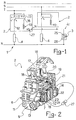
- the numeral 1 generally designates an apparatus for tripping off switches, indicated at 2, by means of a remote control 3.
- the remote control 3 is a pushbutton type of control with an automatic spring bias, while the switches 2 are advantageously of the double-pole type with automatic magnetothermal protection.
- the switches 2 are adapted for mounting within a small frame, not shown, for flush-mounted boxes of civil range electric appliances. Further, such switches 2 would be connected to operate a respective user electric appliance such as a lamp 4 for lighting a civil enclosure.
- each switch 2 is connected serially to a corresponding lamp 4 across a respective live conductor or phase R, S or T of a three-phase system, and a neutral conductor N.
- the switch 2 comprises a central core 5 wherein a pole pair are accommodated, namely a protected pole 6 and a neutral pole 7.
- the protected pole 6 extends between an input terminal 11 and an output terminal 12.
- a fixed contact 8 associated with the input terminal 11, and a moving contact 9 associated with the output terminal 12.
- the neutral pole 7 extends between an input terminal 13 and an output terminal 14. Provided along the pole 7 are a fixed contact 15 associated with the input terminal 13, and a moving contact 16 associated with the output terminal 14.
- the switch 2 further comprises trip-off linkages, generally designated 18, which are supported on the central core 5.
- the linkages 18 comprise a key 17 and a moving contact holder assembly 19. Between the key 17 and the moving contact holder assembly 19 there is provided a toggle mechanism, known per se, designated 20.
- the trip-off linkages 18 also comprise a springloaded lever 21 for clamping the moving contact holder assembly 19 in the switch make position.
- the lever 21 has two lugs, of which the lug 22 on the terminals 13 and 14 side is visible.
- the central core 5 of the switch 2 also accommodates a voltmeter coil 10 of thin wire, at the neutral pole 7.
- the voltmeter coil 10 has a respective pusher 23 adapted to become engaged with the lug 22 of the clamping lever 21 so as to release the moving contact holder assembly 19 and cause the switch to break on energizing the coil 10 electrically.
- One end 24 of the coil 10 is connected to the aforesaid moving contact 16, whereas the other end of the coil is connected to the output terminal 14 via a diode 27.
- One of the terminals of the pushbutton control 3, in particular the terminal 25, is connected to the output terminal 14, and the other terminal 26 of the pushbutton 3 is connected directly to the neutral conductor N.
- the moving contact 16 is connected in a power supply circuit 45 connecting the coil 10 serially with the pushbutton control 3.
- the diode 27 is connected serially to the coil 10, inside the switch 2, to avoid keeping the coil 10 alive as the swith makes to power the lamp 4 electrically.
- the pushbutton control 3 may be a programming device to enable turning off the lights at programmably set times of the day, or a so-called twilight device which becomes operative at a set evening time.
- FIG. 3 a schematical view is shown therein of a first variation of the apparatus according to the invention.
- items and cooperating parts which have the same construction and operate in the same way as the previously described embodiment are designated by the same reference numerals and no further explained herein.
- the diode 27 is connected serially to the coil 10 across the other end thereof and the output terminal 14. Connected to the terminal 14 is also the terminal 25 of the pushbutton control 3.
- both poles i.e. the protected pole 6 and neutral pole 7, from a switch 28 are connected respectively across the phase line F and the lamp 4, and across the neutral conductor N and the lamp 4. This connection is referred to as single-plus-neutral pole.
- the output terminal 12 of the protected pole 6 is connected to one end of the diode 27 whose other end is connected to the coil 10.
- an additional terminal 14 attached laterally of the metal frame 32 carrying the coil 10 and provided with a cable clamp screw 31.
- the end 24 of the coil 10 is connected to the aforesaid metal frame 32 to provide electric connection to said terminal 30.
- inventive apparatus affords the ability to turn off simultaneously and in a centralized manner a plurality of electric appliances, while still enabling local regaining of the functions of each individual appliance by operating its respective switch, which will be kept alive because only its trip-off linkages are remotely controlled through the centralized pushbutton control connected to the voltmeter coil of each switch.
- Another advantage is that the voltmeter coil is connected in the very power supply circuit which it breaks by operating the trip-off linkages, thereby it will not be kept alive.
- the apparatus of this invention also affords a better than halved consumption of cable conductors compared to those required to make up a lighting system according to the pior art. Further, this apparatus may be connected and controlled by a programming device to centrally deactivate the functions of the various electric appliances for set periods of time to save on power consumption.
Landscapes
- Engineering & Computer Science (AREA)
- Power Engineering (AREA)
- Keying Circuit Devices (AREA)
- Selective Calling Equipment (AREA)
- Remote Monitoring And Control Of Power-Distribution Networks (AREA)
- Driving Mechanisms And Operating Circuits Of Arc-Extinguishing High-Tension Switches (AREA)
- Invalid Beds And Related Equipment (AREA)
- Switch Cases, Indication, And Locking (AREA)
- Push-Button Switches (AREA)
- Circuit Arrangement For Electric Light Sources In General (AREA)
- Breakers (AREA)
Claims (4)
- Fernbedienungsgerät für die Auslösung von Schaltern eines Typs, der mindestens einen der Schalter (2, 41, 28) mit mindestens zwei Kontakten und einer Kontaktierungseinrichtung, die geeignet ist, elektrisch die beiden Kontakte miteinander zu verbinden, einen Zentralkern (5), der Auslöseverbindungen (18) unterstützt, die geeignet sind, die Kontaktierungseinrichtung zu betätigen, eine voltmeterspule (10), die innerhalb des Schalter-Zentralkerns (5) zum Betätigen der Auslöseverbindungen aufgenommen ist und einer Leistungszufuhrschaltung (45) aufweist, die mit einer Fernbedienungsdruckknopfsteuerung (3) ausgerüstet ist, um die Spule (10) zu erregen, wobei der Schalter (2) einen Eingangsanschluß (11), der sowohl mit einem der Kontakte als auch mit einer ersten Spannungsversorgungsleitung (R, S, T) verbunden ist, und einen Ausgangsanschluß (12) aufweist, der sowohl mit dem anderen der Kontakte als auch mit einer zweiten Spannungsversorgungsleitung (N) durch eine elektrische Benutzeranwendung (4) verbunden ist, dadurch gekennzeichnet, daß die beiden Kontakte aus einem beweglichen Kontakt, der durch die Kontaktierungseinrichtung (9) getragen ist, und einem festen Kontakt (8) bestehen, die Spule (10) ein Ende mit entweder dem Eingangs- (11) oder dem Ausgangsanschluß (12), zumindest wenn der Schalter (2) geschlossen ist, elektrisch verbunden hat und das andere Ende mit einem zusätzlichen Ausgangsanschluß (14) verbunden ist und die Druckknopfsteuerung (3) ein Ende mit dem zusätzlichen Ausgangsanschluß (14) verbunden hat und ein anderes Ende mit der zweiten Spannungszufuhrleitung (N) verbunden hat.
- Vorrichtung nach Anspruch 1, dadurch gekennzeichnet, daß sie eine Diode (27) aufweist, die in Reihe mit der Voltmeterspule (10) verbunden ist.
- Vorrichtung nach Anspruch 1 oder 2, worin der Schalter ein Doppelpolschalter (2) ist, dadurch gekennzeichnet, daß der Schalter (2) einen zusätzlichen festen Kontakt (15), einen zusätzlichen beweglichen Kontakt und eine zusätzliche Kontaktierungseinrichtung (16), die den beweglichen Kontakt unterstützt und gleichlaufend mit der erstgenannten Kontaktierungseinrichtung (9) betätigbar ist, aufweist und daß die elektrische Verbindung von dem einen Ende der Spule (10) mit dem Eingangs- (11) oder dem Ausgangsanschluß (12) durch die zusätzliche Kontaktierungseinrichtung (16) bewirkt wird.
- Vorrichtung nach Anspruch 1 oder 2, worin der Schalter ein Doppelpolschalter (28) ist, der in der Einzel-Plus-Neutral-Polart mit der elektrischen Anwendung (4) verbunden ist, dadurch gekennzeichnet, daß der Schalter (28) einen zusätzlichen festen Kontakt (15), einen zusätzlichen beweglichen Kontakt und eine zusätzliche Kontaktierungseinrichtung (16), die den beweglichen Kontakt unterstützt und gleichlaufend mit der erstgenannten Kontaktierungseinrichtung (9) betätigbar ist, aufweist und daß die Verbindung des Ausgangsanschlusses (12) mit einer zweiten Spannungszufuhrleitung durch eine elektrische Benutzeranwendung (4) durch die zusätzliche Kontaktierungseinrichtung (16) bewirkt ist.
Priority Applications (1)
| Application Number | Priority Date | Filing Date | Title |
|---|---|---|---|
| AT88830037T ATE88303T1 (de) | 1987-02-09 | 1988-02-03 | Fernbedienungsgeraet fuer die ausloesung von schaltern. |
Applications Claiming Priority (2)
| Application Number | Priority Date | Filing Date | Title |
|---|---|---|---|
| IT1929887 | 1987-02-09 | ||
| IT19298/87A IT1202486B (it) | 1987-02-09 | 1987-02-09 | Apparecchiatura con comando a distanza per l'apertura di interruttori |
Publications (3)
| Publication Number | Publication Date |
|---|---|
| EP0278920A2 EP0278920A2 (de) | 1988-08-17 |
| EP0278920A3 EP0278920A3 (en) | 1990-01-03 |
| EP0278920B1 true EP0278920B1 (de) | 1993-04-14 |
Family
ID=11156523
Family Applications (1)
| Application Number | Title | Priority Date | Filing Date |
|---|---|---|---|
| EP88830037A Expired - Lifetime EP0278920B1 (de) | 1987-02-09 | 1988-02-03 | Fernbedienungsgerät für die Auslösung von Schaltern |
Country Status (11)
| Country | Link |
|---|---|
| US (1) | US4825096A (de) |
| EP (1) | EP0278920B1 (de) |
| JP (1) | JPS63200206A (de) |
| AT (1) | ATE88303T1 (de) |
| BR (1) | BR8800532A (de) |
| DE (1) | DE3880174D1 (de) |
| EG (1) | EG18471A (de) |
| ES (1) | ES2043886T3 (de) |
| IT (1) | IT1202486B (de) |
| MX (1) | MX167278B (de) |
| TN (1) | TNSN88007A1 (de) |
Families Citing this family (6)
| Publication number | Priority date | Publication date | Assignee | Title |
|---|---|---|---|---|
| US4920476A (en) * | 1988-05-27 | 1990-04-24 | Westinghouse Electric Corp. | Electronic control for lighting panelboards |
| FR2660793B1 (fr) * | 1990-04-06 | 1992-07-03 | Telemacenique | Relais thermique. |
| US5199026A (en) * | 1991-02-27 | 1993-03-30 | Memorex Telex N.V. | Token ring wiring concentrator |
| US6728087B1 (en) | 2001-08-02 | 2004-04-27 | Reliance Controls Corporation | Method and apparatus for remotely actuating a circuit protection device |
| ZA200506062B (en) * | 2004-10-04 | 2007-12-27 | Circuit Breaker Ind | Trip indicative rocker switch |
| US9530596B1 (en) * | 2015-12-04 | 2016-12-27 | Steven Alexander Linton | Multiway switching apparatuses for electrical appliances |
Family Cites Families (14)
| Publication number | Priority date | Publication date | Assignee | Title |
|---|---|---|---|---|
| CH409092A (it) * | 1964-04-11 | 1966-03-15 | Bassani Spa | Interruttore automatico magnetotermico |
| US3860910A (en) * | 1973-08-13 | 1975-01-14 | David S Hudson | Electrical switch system for a house or the like |
| US4164719A (en) * | 1978-04-03 | 1979-08-14 | Gould Inc. | Load management apparatus for residential load centers |
| US4308511A (en) * | 1980-01-10 | 1981-12-29 | Westinghouse Electric Corp. | Load management circuit breaker |
| US4367510A (en) * | 1980-05-16 | 1983-01-04 | Fuji Electric Co., Ltd. | Remote control switch device |
| FR2511206A1 (fr) * | 1981-08-07 | 1983-02-11 | Hirsch Jean Jacques | Dispositif de visualisation pour telecommande par telerupteur ou relais bistable |
| JPS58131636A (ja) * | 1982-01-29 | 1983-08-05 | 松下電工株式会社 | リモ−トコントロ−ル式回路しや断器 |
| DE3576428D1 (de) * | 1984-12-24 | 1990-04-12 | Matsushita Electric Works Ltd | Fernsteuerbares relais. |
| US4604596A (en) * | 1985-02-01 | 1986-08-05 | Matsushita Electric Works, Ltd. | Remotely controllable circuit breaker |
| JPS61230231A (ja) * | 1985-04-04 | 1986-10-14 | 三菱電機株式会社 | 遠隔操作式回路しや断器 |
| US4636760A (en) * | 1985-04-10 | 1987-01-13 | Westinghouse Electric Corp. | Low voltage circuit breaker with remote switching function |
| FR2590404B1 (fr) * | 1985-11-15 | 1990-08-10 | Telemecanique Electrique | Disjoncteur comportant un electro-aimant de telecommande d'un contact escamotable d'interrupteur et un organe de transmission du mouvement de l'armature de l'electro-aimant en un point de ce contact centre sur l'axe de deplacement de l'armature |
| FR2590403B1 (fr) * | 1985-11-15 | 1990-08-10 | Telemecanique Electrique | Disjoncteur comportant un electro-aimant de telecommande d'un contact escamotable d'interrupteur et un organe de transmission du mouvement de l'armature de l'electro-aimant en un point de ce contact decale par rapport au deplacement de l'armature |
| US4725799A (en) * | 1986-09-30 | 1988-02-16 | Westinghouse Electric Corp. | Circuit breaker with remote control |
-
1987
- 1987-02-09 IT IT19298/87A patent/IT1202486B/it active
-
1988
- 1988-01-26 US US07/148,769 patent/US4825096A/en not_active Expired - Lifetime
- 1988-02-03 EP EP88830037A patent/EP0278920B1/de not_active Expired - Lifetime
- 1988-02-03 DE DE8888830037T patent/DE3880174D1/de not_active Expired - Lifetime
- 1988-02-03 AT AT88830037T patent/ATE88303T1/de not_active IP Right Cessation
- 1988-02-03 ES ES88830037T patent/ES2043886T3/es not_active Expired - Lifetime
- 1988-02-05 JP JP63025530A patent/JPS63200206A/ja active Pending
- 1988-02-07 EG EG62/88A patent/EG18471A/xx active
- 1988-02-08 TN TNTNSN88007A patent/TNSN88007A1/fr unknown
- 1988-02-08 MX MX010328A patent/MX167278B/es unknown
- 1988-02-09 BR BR8800532A patent/BR8800532A/pt not_active IP Right Cessation
Also Published As
| Publication number | Publication date |
|---|---|
| JPS63200206A (ja) | 1988-08-18 |
| MX167278B (es) | 1993-03-15 |
| EG18471A (en) | 1993-04-30 |
| TNSN88007A1 (fr) | 1990-07-10 |
| US4825096A (en) | 1989-04-25 |
| DE3880174D1 (de) | 1993-05-19 |
| ATE88303T1 (de) | 1993-04-15 |
| BR8800532A (pt) | 1988-09-27 |
| IT1202486B (it) | 1989-02-09 |
| ES2043886T3 (es) | 1994-01-01 |
| IT8719298A0 (it) | 1987-02-09 |
| EP0278920A2 (de) | 1988-08-17 |
| EP0278920A3 (en) | 1990-01-03 |
Similar Documents
| Publication | Publication Date | Title |
|---|---|---|
| US3973818A (en) | Multi-purpose prefabricated electrical installation | |
| JP4409140B2 (ja) | コンタクタ・ブレーカー | |
| US3979576A (en) | Electric heating element control circuit | |
| US5657193A (en) | Electronic control module for motor controller units | |
| DE3475589D1 (en) | Power supply system | |
| JPH027152B2 (de) | ||
| KR930007087B1 (ko) | 다회로제어장치 | |
| SU1672936A3 (ru) | Устройство управлени | |
| JPH05508515A (ja) | モジュール配線システム | |
| US5705862A (en) | Configurable panelboard for a plurality of electrical switching apparatus | |
| US4825096A (en) | Remote control apparatus for tripping off switches | |
| CA2356972C (en) | Mode selectable power receptacle | |
| US3246179A (en) | Electrical outlet having double throw switch for connection to power line through alternate circuit paths | |
| DE69202002D1 (de) | Lasttrenngerät für elektrische Schaltung. | |
| DE68911753D1 (de) | Schaltschrank für elektrische Anlagen. | |
| US5557498A (en) | Switching apparatus including a displaceable disconnecting device and an auxiliary circuit | |
| US2771521A (en) | Remote control key switch | |
| JP4676663B2 (ja) | 住宅用分電盤 | |
| JP6455771B2 (ja) | 一括開閉装置および分電盤装置 | |
| SE9003734D0 (sv) | Relaesaekring | |
| US3937977A (en) | Combination disposer run and dishwasher disconnect switch for kitchen module | |
| CA2134954C (en) | Standby power apparatus | |
| GB2144002A (en) | Domestic electrical wiring system | |
| NZ217062A (en) | Load breaking switch-three pole operation | |
| US11538649B2 (en) | Circuit breaker housing |
Legal Events
| Date | Code | Title | Description |
|---|---|---|---|
| PUAI | Public reference made under article 153(3) epc to a published international application that has entered the european phase |
Free format text: ORIGINAL CODE: 0009012 |
|
| AK | Designated contracting states |
Kind code of ref document: A2 Designated state(s): AT BE CH DE ES FR GB GR LI LU NL SE |
|
| PUAL | Search report despatched |
Free format text: ORIGINAL CODE: 0009013 |
|
| AK | Designated contracting states |
Kind code of ref document: A3 Designated state(s): AT BE CH DE ES FR GB GR LI LU NL SE |
|
| 17P | Request for examination filed |
Effective date: 19900124 |
|
| 17Q | First examination report despatched |
Effective date: 19910821 |
|
| GRAA | (expected) grant |
Free format text: ORIGINAL CODE: 0009210 |
|
| AK | Designated contracting states |
Kind code of ref document: B1 Designated state(s): AT BE CH DE ES FR GB GR LI LU NL SE |
|
| PG25 | Lapsed in a contracting state [announced via postgrant information from national office to epo] |
Ref country code: SE Effective date: 19930414 Ref country code: NL Effective date: 19930414 Ref country code: LI Effective date: 19930414 Ref country code: GR Free format text: LAPSE BECAUSE OF FAILURE TO SUBMIT A TRANSLATION OF THE DESCRIPTION OR TO PAY THE FEE WITHIN THE PRESCRIBED TIME-LIMIT Effective date: 19930414 Ref country code: DE Effective date: 19930414 Ref country code: CH Effective date: 19930414 Ref country code: BE Effective date: 19930414 Ref country code: AT Effective date: 19930414 |
|
| REF | Corresponds to: |
Ref document number: 88303 Country of ref document: AT Date of ref document: 19930415 Kind code of ref document: T |
|
| REF | Corresponds to: |
Ref document number: 3880174 Country of ref document: DE Date of ref document: 19930519 |
|
| RAP2 | Party data changed (patent owner data changed or rights of a patent transferred) |
Owner name: BTICINO S.P.A. |
|
| REG | Reference to a national code |
Ref country code: CH Ref legal event code: PUE Owner name: BTICINO S.P.A. Ref country code: CH Ref legal event code: PL |
|
| ET | Fr: translation filed | ||
| NLV1 | Nl: lapsed or annulled due to failure to fulfill the requirements of art. 29p and 29m of the patents act | ||
| REG | Reference to a national code |
Ref country code: ES Ref legal event code: FG2A Ref document number: 2043886 Country of ref document: ES Kind code of ref document: T3 |
|
| PG25 | Lapsed in a contracting state [announced via postgrant information from national office to epo] |
Ref country code: GB Effective date: 19940203 |
|
| PGFP | Annual fee paid to national office [announced via postgrant information from national office to epo] |
Ref country code: ES Payment date: 19940209 Year of fee payment: 7 |
|
| PLBE | No opposition filed within time limit |
Free format text: ORIGINAL CODE: 0009261 |
|
| STAA | Information on the status of an ep patent application or granted ep patent |
Free format text: STATUS: NO OPPOSITION FILED WITHIN TIME LIMIT |
|
| PG25 | Lapsed in a contracting state [announced via postgrant information from national office to epo] |
Ref country code: LU Free format text: LAPSE BECAUSE OF NON-PAYMENT OF DUE FEES Effective date: 19940228 |
|
| PGFP | Annual fee paid to national office [announced via postgrant information from national office to epo] |
Ref country code: FR Payment date: 19940228 Year of fee payment: 7 |
|
| 26N | No opposition filed | ||
| GBPC | Gb: european patent ceased through non-payment of renewal fee |
Effective date: 19940203 |
|
| PG25 | Lapsed in a contracting state [announced via postgrant information from national office to epo] |
Ref country code: ES Free format text: LAPSE BECAUSE OF NON-PAYMENT OF DUE FEES Effective date: 19950204 |
|
| PG25 | Lapsed in a contracting state [announced via postgrant information from national office to epo] |
Ref country code: FR Effective date: 19951031 |
|
| REG | Reference to a national code |
Ref country code: FR Ref legal event code: ST |
|
| REG | Reference to a national code |
Ref country code: ES Ref legal event code: FD2A Effective date: 19990301 |