EP0278921A2 - Une presse pour mouler des articles en matière plastique pourvue d'un dispositif pour échanger les moules - Google Patents
Une presse pour mouler des articles en matière plastique pourvue d'un dispositif pour échanger les moules Download PDFInfo
- Publication number
- EP0278921A2 EP0278921A2 EP88830041A EP88830041A EP0278921A2 EP 0278921 A2 EP0278921 A2 EP 0278921A2 EP 88830041 A EP88830041 A EP 88830041A EP 88830041 A EP88830041 A EP 88830041A EP 0278921 A2 EP0278921 A2 EP 0278921A2
- Authority
- EP
- European Patent Office
- Prior art keywords
- die holder
- dies
- turret head
- die
- press
- Prior art date
- Legal status (The legal status is an assumption and is not a legal conclusion. Google has not performed a legal analysis and makes no representation as to the accuracy of the status listed.)
- Withdrawn
Links
Images

Classifications
-
- B—PERFORMING OPERATIONS; TRANSPORTING
- B29—WORKING OF PLASTICS; WORKING OF SUBSTANCES IN A PLASTIC STATE IN GENERAL
- B29C—SHAPING OR JOINING OF PLASTICS; SHAPING OF MATERIAL IN A PLASTIC STATE, NOT OTHERWISE PROVIDED FOR; AFTER-TREATMENT OF THE SHAPED PRODUCTS, e.g. REPAIRING
- B29C31/00—Handling, e.g. feeding of the material to be shaped, storage of plastics material before moulding; Automation, i.e. automated handling lines in plastics processing plants, e.g. using manipulators or robots
- B29C31/006—Handling moulds, e.g. between a mould store and a moulding machine
-
- B—PERFORMING OPERATIONS; TRANSPORTING
- B29—WORKING OF PLASTICS; WORKING OF SUBSTANCES IN A PLASTIC STATE IN GENERAL
- B29C—SHAPING OR JOINING OF PLASTICS; SHAPING OF MATERIAL IN A PLASTIC STATE, NOT OTHERWISE PROVIDED FOR; AFTER-TREATMENT OF THE SHAPED PRODUCTS, e.g. REPAIRING
- B29C33/00—Moulds or cores; Details thereof or accessories therefor
- B29C33/30—Mounting, exchanging or centering
- B29C33/306—Exchangeable mould parts, e.g. cassette moulds, mould inserts
-
- B—PERFORMING OPERATIONS; TRANSPORTING
- B29—WORKING OF PLASTICS; WORKING OF SUBSTANCES IN A PLASTIC STATE IN GENERAL
- B29L—INDEXING SCHEME ASSOCIATED WITH SUBCLASS B29C, RELATING TO PARTICULAR ARTICLES
- B29L2031/00—Other particular articles
- B29L2031/48—Wearing apparel
- B29L2031/50—Footwear, e.g. shoes or parts thereof
Definitions
- This invention relates to a press for molding plastics articles, which is particularly but not exclusively intended for molding footwear articles such as ski boots and the like.
- the molding press to which this invention relates is of a type which comprises a pair of superimposed plate-like dies supported on plural pillars, with at least one of said dies being movable along said pillars toward and away from the other of said dies to close and open the die pair, and at least one mold movable from a molding position whereat it is located between the closed dies to a shake-out position away from said open dies.
- a male pattern is meant which has the same shape as a footwear article to be molded.
- known design presses have employed dies which form, when in their closed condition, two cavities corresponding to the right-hand and left-hand fitting boot in a boot pair, respectively; first and second mold pairs are secured cantilever-fashion removably on opposed sides of one and the same die holder.
- the die holder is carried pivotally on one press pillar to which it is mounted such that while one mold pair are in a molding position between the closed dies, the other mold pair would be in the position for shaking out the articles (boots, ski boots, and the like) being molded thereon.
- the molds can be positioned adjustably on the die holders for locking aligned to and in registry with their respective die cavities.
- the press comprises a fast-action mold exchange device including a turret head mounted pivotally to said one pillar and being displaceable slidingly therealong, at least one die holder for said at least one mold, means on said turret head and counter-means on said die holder of mutual registering and substantially quick coupling together.
- the "die exchange" step is reduced to a simple operation of uncoupling a used die holder and coupling a new appropriate die holder from/to the turret head.
- Such an operation can be so quickly and easily performed as not to interfere substantially with the press working cycle, thereby reducing substantially the downtime affecting heretofore the working cycles of conventional presses.
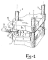
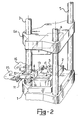
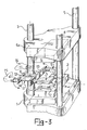
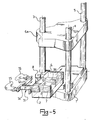
- a molding press is shown therein for molding plastics footwear articles, in particular ski boot shells, denoted by the reference character S.
- such a press comprises a bed 1 on which a plate-like die 2 is secured removably in a manner known per se and no further illustrated, and three identical, vertically extending, cylindrical pillars 3, 4, 5 located at the apices of an equilateral triangle. These pillars provide support and slideways for a plate 6a to which a second die 6 is secured in a conventional manner no further illustrated.
- a conventional drive means is provided to displace the die 6 toward and away from the underlying die 2, thereby providing the closed die and opened die positions in the press working cycle.
- the dies 2 and 6 are formed with respective impressions, collectively indicated at 7 (in the Figures, only those of the die 2 are visible), which with the dies in the closed position form respective cavities shaped to a desired pattern of a footwear article to be produced.
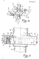
- a turret head 8 of square shape At a location included between the dies 2 and 6, there is mounted on the pillar 3 a turret head 8 of square shape. More specifically ( Figure 6), the turret head 8 is made rigid rotatively, as by means of a key 9, with a power driven tube 10 mounted rotatively on the pillar 3 coaxially therewith and being slidable along the pillar.
- a die holder which comprises two identical, stiffened and parallel rods 12, 13 held apart, in the vicinity of one end thereof, by a cross-piece 14 imparting an essentially U-shaped configuration to the die holder 11 as a whole.
- the distance separating the rods 12 and 13 is equal to the length of the side of the square turret head 8 on which the die holder 11 shall have to be mounted in a manner to be described.
- the rods 12 and 13 of the die holder 11 are provided with a means of mounting respective mold pairs 15, 16 and 17, 18, having volumes and shapes adapted for cooperation with the cavities formed by the dies 2 and 6, adjustably in position to mold desired footwear articles.
- cylindrical cavities 21 in fluid communication with a source of a pressurized fluid, e.g. an oil; with reference to Figure 7, a small piston 22 is movable within each of said cylindrical cavities 21 whose rod 23 has a hammerhead-shaped end 23a standing proud of the top contour of a respective one of the cylindrical cavities 21 and being closed by disk-like covers 21a.
- a source of a pressurized fluid e.g. an oil
- Belleville springs 24 are arranged to act on the small pistons 22 which hold said pistons 22 in a normally depressed position.
- the opposite sides of the turret head 8 adapted for association with the rods 12 and 13 have outer walls suitably coated with a friction-reducing material as indicated at 25.
- a plurality of die holders 11 quite identical of the one described hereinabove are stored in a die magazine and each of them will be provided with respective mold pairs, with one of said pairs already enclosed between two dies and the other adjusted finely to an exact position between two more dies.
- the molding cycle can be started.
- the dies 2 and 6 are set on the press in their closed condition with a first mold pair locked in a registered position within their cavities ( Figure 1).
- the (upper) die 6 is raised ( Figure 2), and the turret head 8 is next raised which entrains the die holder 11 along with it ( Figure 3).
- the first-mentioned mold pair are drawn out of the lower die 2.
- the turret head 8 is then imparted an angular displacement through 180° and the molds, on which the articles S have been molded, are brought to the shake-out position, while at the same time, the other mold pair is positioned between the open dies 2 and 6.
- the turret head 8 is moved back down such that the new mold pair can can locate themselves inside the cavities 7 of the die 2.
- the die 6 is then brought down to the closed die position.
- the molding cycle is repeated while at the same time completing the shaking out of the first pair of molded articles S.
- a new die holder 11 is picked up complete with respective mold pairs one of which is enclosed between a pair of dies. This die holder is brought to a point close to the press and subjected to a preheating step.
- the die holder 11 By raising the small pistons 22, the die holder 11 so far at work on the press is released from the turret head 8, and can be withdrawn therefrom by any conventional means to entrain the last pair of molded articles and the closed dies along with it. On the turret head 8 being so cleared, the new die holder 11 is fitted thereon in a substantially cartridge-like fashion. The rods 12 and 13 will engage slidingly with the opposite sides of the turret 8 until the cross-piece 14 strikes the abutment 26 formed on the head.
- the fitting provided between the die holder 11 and the turret 8 is of the quick coupling kind with exact positioning features of the positive mechanical abutment or detent type.
- the dies are secured by conventional means on the press already in their working positions, thereby a fresh production cycle can be initiated.
- the die holders 11 may have different constructions, and different constructions may also have the indexing and quick coupling means which ensure precise interfit of the turret head 8 and each of a plurality of die holders.
Landscapes
- Engineering & Computer Science (AREA)
- Mechanical Engineering (AREA)
- Robotics (AREA)
- Moulds For Moulding Plastics Or The Like (AREA)
- Mounting, Exchange, And Manufacturing Of Dies (AREA)
Applications Claiming Priority (2)
| Application Number | Priority Date | Filing Date | Title |
|---|---|---|---|
| IT8719289A IT1215350B (it) | 1987-02-06 | 1987-02-06 | Pressa per lo stampaggio di articoli di materia plastica con dispositivo di cambio degli stampi. |
| IT1928987 | 1987-02-06 |
Publications (2)
| Publication Number | Publication Date |
|---|---|
| EP0278921A2 true EP0278921A2 (fr) | 1988-08-17 |
| EP0278921A3 EP0278921A3 (fr) | 1990-06-27 |
Family
ID=11156452
Family Applications (1)
| Application Number | Title | Priority Date | Filing Date |
|---|---|---|---|
| EP88830041A Withdrawn EP0278921A3 (fr) | 1987-02-06 | 1988-02-03 | Une presse pour mouler des articles en matière plastique pourvue d'un dispositif pour échanger les moules |
Country Status (2)
| Country | Link |
|---|---|
| EP (1) | EP0278921A3 (fr) |
| IT (1) | IT1215350B (fr) |
Cited By (5)
| Publication number | Priority date | Publication date | Assignee | Title |
|---|---|---|---|---|
| GB2253806A (en) * | 1991-02-27 | 1992-09-23 | Katsuji Takeno | Mould and positioning holder for mould |
| GB2363752A (en) * | 2000-06-22 | 2002-01-09 | Plasmedics Ltd | Plastics packaging by thermoforming |
| EP1279473A1 (fr) * | 2001-07-23 | 2003-01-29 | FRIMO Group GmbH & Co. KG | Dispositif pour la production des éléments en matériau composite |
| ES2190831A1 (es) * | 2000-03-22 | 2003-08-16 | Euro Seating Int Sa | Procedimiento de obtencion de pies centrales de butacas para cines o similares y pie central asi obtenido. |
| NL1023250C2 (nl) * | 2003-04-23 | 2004-11-01 | F T Engineering B V | Wisselinrichting voor een matrijs. |
Family Cites Families (8)
| Publication number | Priority date | Publication date | Assignee | Title |
|---|---|---|---|---|
| US3131432A (en) * | 1961-02-16 | 1964-05-05 | United Shoe Machinery Corp | Plastic injection molding machines |
| US3429007A (en) * | 1965-04-01 | 1969-02-25 | Katashi Aoki | Injection molding apparatus for making shoes |
| US3350748A (en) * | 1965-07-27 | 1967-11-07 | United Shoe Machinery Corp | Quick change mold assemblies |
| FR1476421A (fr) * | 1966-04-19 | 1967-04-07 | Outil pour le moulage par injection de chaussures montantes | |
| DE2421811C2 (de) * | 1974-05-06 | 1984-12-13 | Karl 7298 Loßburg Hehl | Formschließeinheit für eine Kunststoff-Spritzgießmaschine mit einem Schiebetisch |
| JPS556495B2 (fr) * | 1974-11-14 | 1980-02-16 | ||
| US4009983A (en) * | 1976-01-16 | 1977-03-01 | Arthur William Jacobs | Hydraulic mold clamping mechanism for injection molding machine |
| US8070003B2 (en) * | 2009-04-27 | 2011-12-06 | Johnson & Johnson Consumer Companies, Inc. | Package feature |
-
1987
- 1987-02-06 IT IT8719289A patent/IT1215350B/it active
-
1988
- 1988-02-03 EP EP88830041A patent/EP0278921A3/fr not_active Withdrawn
Cited By (7)
| Publication number | Priority date | Publication date | Assignee | Title |
|---|---|---|---|---|
| GB2253806A (en) * | 1991-02-27 | 1992-09-23 | Katsuji Takeno | Mould and positioning holder for mould |
| ES2190831A1 (es) * | 2000-03-22 | 2003-08-16 | Euro Seating Int Sa | Procedimiento de obtencion de pies centrales de butacas para cines o similares y pie central asi obtenido. |
| GB2363752A (en) * | 2000-06-22 | 2002-01-09 | Plasmedics Ltd | Plastics packaging by thermoforming |
| GB2363752B (en) * | 2000-06-22 | 2004-01-14 | Plasmedics Ltd | Plastic packaging |
| EP1279473A1 (fr) * | 2001-07-23 | 2003-01-29 | FRIMO Group GmbH & Co. KG | Dispositif pour la production des éléments en matériau composite |
| NL1023250C2 (nl) * | 2003-04-23 | 2004-11-01 | F T Engineering B V | Wisselinrichting voor een matrijs. |
| WO2004094126A3 (fr) * | 2003-04-23 | 2005-03-03 | F T Engineering B V | Dispositif de deplacement de moule |
Also Published As
| Publication number | Publication date |
|---|---|
| IT8719289A0 (it) | 1987-02-06 |
| EP0278921A3 (fr) | 1990-06-27 |
| IT1215350B (it) | 1990-02-08 |
Similar Documents
| Publication | Publication Date | Title |
|---|---|---|
| US2442338A (en) | Apparatus for and method of forming sheet material | |
| CN211915140U (zh) | 一种便于工件夹紧的冲压机 | |
| CN107716707A (zh) | 一种全自动两工位一体机 | |
| GB857973A (en) | Improvements in or relating to apparatus for the production of shaped plastic workpieces | |
| CN109367247B (zh) | 一种自动对中笔记本键盘外壳快速打标的打标机 | |
| JPS6127168B2 (fr) | ||
| GB1481732A (en) | Presses | |
| CN210816978U (zh) | 一种外壳自动加工生产线 | |
| JPH08224624A (ja) | スクラップ排出方法およびスクラップ排出装置 | |
| US2525609A (en) | Vulcanizing press | |
| CN215203111U (zh) | 一种换向器的生产设备 | |
| CN118218920A (zh) | 一种家具五金件加工方法 | |
| CN210099125U (zh) | 一种充气气嘴切割设备 | |
| CN209502726U (zh) | 一种方便落料的折弯模具 | |
| CN114871333A (zh) | 一种温度传感器生产装置 | |
| JPH0123286B2 (fr) | ||
| CN220426459U (zh) | 一种送料机构及其冲压模具 | |
| CN222603918U (zh) | 一种压底机 | |
| CN215845260U (zh) | 一种可以防止拉伸产品起皱的模具结构 | |
| CN217944413U (zh) | 一种异形板加工模具 | |
| CN220679074U (zh) | 一种保温杯的反边工装 | |
| CN222890370U (zh) | 压边装置 | |
| JPS6059057B2 (ja) | エツジベント工法及びその装置 | |
| KR930011207B1 (ko) | 개량된 신발창 성형장치 | |
| CN217704387U (zh) | 一种具有顶升送料机构的iml注塑成型设备 |
Legal Events
| Date | Code | Title | Description |
|---|---|---|---|
| PUAI | Public reference made under article 153(3) epc to a published international application that has entered the european phase |
Free format text: ORIGINAL CODE: 0009012 |
|
| AK | Designated contracting states |
Kind code of ref document: A2 Designated state(s): AT BE CH DE ES FR GB GR LI LU NL SE |
|
| PUAL | Search report despatched |
Free format text: ORIGINAL CODE: 0009013 |
|
| AK | Designated contracting states |
Kind code of ref document: A3 Designated state(s): AT BE CH DE ES FR GB GR LI LU NL SE |
|
| 17P | Request for examination filed |
Effective date: 19900629 |
|
| 17Q | First examination report despatched |
Effective date: 19910626 |
|
| STAA | Information on the status of an ep patent application or granted ep patent |
Free format text: STATUS: THE APPLICATION IS DEEMED TO BE WITHDRAWN |
|
| 18D | Application deemed to be withdrawn |
Effective date: 19930112 |