EP0279344A2 - Tuyau flexible - Google Patents
Tuyau flexible Download PDFInfo
- Publication number
- EP0279344A2 EP0279344A2 EP88101938A EP88101938A EP0279344A2 EP 0279344 A2 EP0279344 A2 EP 0279344A2 EP 88101938 A EP88101938 A EP 88101938A EP 88101938 A EP88101938 A EP 88101938A EP 0279344 A2 EP0279344 A2 EP 0279344A2
- Authority
- EP
- European Patent Office
- Prior art keywords
- hose
- flexible hose
- inner tube
- receiving
- Prior art date
- Legal status (The legal status is an assumption and is not a legal conclusion. Google has not performed a legal analysis and makes no representation as to the accuracy of the status listed.)
- Withdrawn
Links
Images
Classifications
-
- A—HUMAN NECESSITIES
- A47—FURNITURE; DOMESTIC ARTICLES OR APPLIANCES; COFFEE MILLS; SPICE MILLS; SUCTION CLEANERS IN GENERAL
- A47L—DOMESTIC WASHING OR CLEANING; SUCTION CLEANERS IN GENERAL
- A47L9/00—Details or accessories of suction cleaners, e.g. mechanical means for controlling the suction or for effecting pulsating action; Storing devices specially adapted to suction cleaners or parts thereof; Carrying-vehicles specially adapted for suction cleaners
- A47L9/24—Hoses or pipes; Hose or pipe couplings
-
- F—MECHANICAL ENGINEERING; LIGHTING; HEATING; WEAPONS; BLASTING
- F16—ENGINEERING ELEMENTS AND UNITS; GENERAL MEASURES FOR PRODUCING AND MAINTAINING EFFECTIVE FUNCTIONING OF MACHINES OR INSTALLATIONS; THERMAL INSULATION IN GENERAL
- F16L—PIPES; JOINTS OR FITTINGS FOR PIPES; SUPPORTS FOR PIPES, CABLES OR PROTECTIVE TUBING; MEANS FOR THERMAL INSULATION IN GENERAL
- F16L11/00—Hoses, i.e. flexible pipes
- F16L11/04—Hoses, i.e. flexible pipes made of rubber or flexible plastics
- F16L11/11—Hoses, i.e. flexible pipes made of rubber or flexible plastics with corrugated wall
- F16L11/118—Hoses, i.e. flexible pipes made of rubber or flexible plastics with corrugated wall having arrangements for particular purposes, e.g. electrically conducting
-
- F—MECHANICAL ENGINEERING; LIGHTING; HEATING; WEAPONS; BLASTING
- F16—ENGINEERING ELEMENTS AND UNITS; GENERAL MEASURES FOR PRODUCING AND MAINTAINING EFFECTIVE FUNCTIONING OF MACHINES OR INSTALLATIONS; THERMAL INSULATION IN GENERAL
- F16L—PIPES; JOINTS OR FITTINGS FOR PIPES; SUPPORTS FOR PIPES, CABLES OR PROTECTIVE TUBING; MEANS FOR THERMAL INSULATION IN GENERAL
- F16L11/00—Hoses, i.e. flexible pipes
- F16L11/04—Hoses, i.e. flexible pipes made of rubber or flexible plastics
- F16L11/11—Hoses, i.e. flexible pipes made of rubber or flexible plastics with corrugated wall
- F16L11/118—Hoses, i.e. flexible pipes made of rubber or flexible plastics with corrugated wall having arrangements for particular purposes, e.g. electrically conducting
- F16L11/1185—Hoses, i.e. flexible pipes made of rubber or flexible plastics with corrugated wall having arrangements for particular purposes, e.g. electrically conducting electrically conducting
Definitions
- the invention relates to a flexible hose according to the preamble of claim 1.
- a vacuum cleaner hose with an inner hose on which a flexible band is wound in a helical fashion (DE-OS 25 05 144).
- the tape has incisions or grooves which, after the tape has been wound, lie behind one another in a helical fashion. In total, this is intended to form a helical groove into which electrical conductors can be inserted or drawn.
- the incisions are particularly on the inside of the band. They have a cross section such that the electrical conductors can move to a certain extent in the longitudinal direction.
- An outer tube which is formed in particular as a jacket made of braided material, surrounds the band in order to hold and protect the electrical conductors in the groove. The sheathing is applied to the reinforced inner tube after the electrical conductors are inserted in the groove.
- a disadvantage of this hose construction is in particular that the type and number of electrical conductors must be determined during the manufacture of the hose, since these cannot be subsequently inserted into the groove.
- the spiral is weakened by the incisions.
- linear contact areas arise between the incision and the conductor, which mechanically stress the latter, particularly when the flexible hose is bent.
- the electrical conductor is only protected from the outside by the sheath or jacket or the outer tube.
- Another known flexible plastic hose essentially consists of an inner hose, which can be produced as a smooth or ribbed, extruded or wound, and possibly reinforced hose or as a cable, and an expediently very thin outer hose encasing it, which has a circular cross-section (DE- OS 29 51 630, U.S. Patent 43 68 348).
- the inner tube and also the outer tube are made of thermoplastic or elastomeric material.
- an additional cable or a further thin hose should be arranged essentially in the longitudinal direction of these hoses.
- a channel is formed from the inner tube by deformation, e.g. Pressing or heat deformation permanently formed, in which the additional element is inserted.
- the shape of the channel must be determined according to the additional element to be inserted. This means that the plastic hose cannot be variably equipped with the additional elements (energy conductors) at a later point in time after the channel has been produced, unless a cross-section of the channel, which essentially limits the clear inner space of the inner hose, is formed from the beginning.
- the prior art also includes a process for the production of suction hoses, in particular for vacuum cleaners with electrical lines which are guided along the suction hose (DE-OS 25 18 990).
- the suction hose is produced with at least one guide channel provided in the hose wall in one operation, preferably by extrusion.
- the guide channel is on the outside of the hose wall.
- the guide channel can are expanded in cross-section during or after manufacture, after which the electrical lines are subsequently introduced into the expanded guide channel.
- the disadvantage of this suction hose is the arrangement of the guide channel on the outside of the hose wall, which only little protects the electrical lines introduced.
- the guide channel runs along the circumference of the suction hose in a straight line or in an elongated helix.
- a flexible connecting line with a flexible protective jacket that runs in a helical shape and in which a first flexible hose and, concentrically to this inside, a further flexible hose are arranged.
- a further channel is formed between the two hoses, which can conduct a medium or possibly accommodate a control cable. Additional means, in particular centering disks, are provided on the hose ends for centering the two hoses, which complicate its assembly.
- a flexible hose which has a hose wall consisting of at least a first inner hose and an outer hose, in which a flattened pocket extending in the longitudinal direction of the hose is provided for receiving at least one energy conductor.
- any control cable that may have been introduced into the cylindrical cavity between the two hoses has a greater range of motion, in particular in the circumferential direction of the connecting line, and can therefore deform indefinitely and rub during movement.
- an inner partition is arranged in a single flexible hose arranged in the protective jacket. The partition lies in or parallel to a longitudinal plane of the hose, in which the longitudinal axis also lies. The flexibility of the hose in a plane in which the straight dividing wall lies, which is difficult to avoid, is restricted.
- the registration is based on the object of providing a flexible hose of the type mentioned at the outset, which can also be optionally equipped with the desired additional energy conductors in an uncomplicated manner even after its manufacture, but as a result the hose should be stiffened as little as possible.
- the energy conductors inserted into the hose should be protected as well as possible against external damage.
- the hose should be characterized by an appealing, smooth surface appearance.
- the flexible hose can initially only be prefabricated with the pocket, while the user can select the energy conductors to be inserted into the pocket at a later point in time.
- the pocket receives the energy conductor or conductors, this does not result in an external bulging of the hose, since the pocket, due to the reinforcement lying opposite it, can essentially only elastically expand inwards to the longitudinal axis of the hose. Since the energy conductors are not only held in places by the reinforcement, but are surrounded by the pocket that extends over the length of the hose, the energy conductors are well protected against external damage. This also means that there is no fear of heavy loads on the energy conductors due to the reinforcement itself.
- Both electrical conductors and optical conductors in the form of glass fibers or else pneumatic or hydraulic conductors, in particular in the form of plastic tubes, are suitable as energy conductors that can be inserted into the pocket.
- the energy conductors can be used to influence physical quantities such as the flow and temperature of a mass flowing through the hose at the delivery point of the mass into the hose.
- this device can be switched on or off by a switch which is arranged on an end of the vacuum cleaner hose facing away from the device, which is normally gripped by the operator or caregiver.
- Another application is the conduction of electrical energy from a vacuum cleaner body to a drive motor rotating brushes which are arranged on a suction head.
- the energy conductor in the pocket is particularly protected if it is inside the first inner tube, i.e. is arranged adjacent to the clear passage space of the flexible hose. In this case, the energy conductor is additionally protected by the first inner hose. If the bag is stretched elastically to accommodate its energy source, this only has a practical effect on the part of the bag facing the clear passage space, since the expansion hardly extends further outwards through the first inner tube and the reinforcement and the outer tube.
- the elastic pocket of the flexible hose for receiving the energy carrier or the energy carriers is preferably opened only as much as the easy introduction of this energy carrier requires, and is not overstretched. This also minimizes the inward deformation of the pocket to the clear passage space in the inner tube.
- a variant of the flexible hose, in which the pocket is arranged in the first inner hose, is characterized in that in the first inner hose a thin-walled second inner hose made of thermoplastic or elastomeric material is arranged substantially adjacent and in that the first and the second inner hose leaving an area that forms the pocket firmly connected.
- Plastomeric as well as elastomeric plastics are suitable for the production of the first and the second inner tube as well as the outer tube.
- Such hoses can be economically produced in the extrusion process.
- the first inner hose can be connected to the first extruded second inner hose and with the aid of glue or by welding to the second inner hose so that only the area of the pocket is not glued or welded.
- the construction of the hose according to claim 4 is particularly advantageous, since the manufacture of this hose can be designed to save space.
- Another variant of the flexible hose, in which the pocket is arranged in the first inner hose, consists in that in the first inner hose a thin-walled second inner hose made of thermoplastic or elastomeric material is arranged essentially in contact and that the first and the second inner hose cover the entire surface are connected to one another in such a way that they can be separated in an area which forms the pocket by means of an introduced separating film or a separating means.
- This second variant of the hose can advantageously be produced by multiple extrusion.
- a separating plastic is extruded into the area of the pocket between the first and the second inner tube.
- the separating plastic can be, for example, a plastomeric polyolefin.
- the first inner tube which has been extruded, can be coated over its entire surface with adhesive, to which the separating film or the separating agent is continuously applied in the region in which the pocket is to be formed. Then the first inner tube is extruded above it, which connects to the second inner tube except in the area of the pocket in which the separating film or the separating agent is located.
- further inner tubes can also be extruded one above the other before winding up the helical reinforcement, in order to enclose at least one pocket between each two inner tubes.
- a flat, thin-walled receiving hose serves as the pocket.
- the receiving hose can be arranged in a variety of ways under the reinforcement, not only between a first and a second inner hose, but also outside between an inner hose and the reinforcement and within only a single first inner hose, so that it connects to the clear passage space in it Inner hose immediately adjacent.
- the receiving hose as a pocket provides additional mechanical reinforcement and electrical insulation of the energy conductor received by it. The energy conductor - or several energy conductors if necessary - are therefore well protected in the receiving hose.
- the wall of the flat receiving tube can consist of a thermoplastic or elastomeric material. Plastics with a Shore A hardness range between 45-80 are suitable.
- the wall of the hose is so soft that it can be wound up into a flattened band, for example on the first inner hose.
- the wall thickness of the flattened receiving tube is preferably between 0.2 mm and 1 mm.
- the width of the flat receiving tube can be up to several centimeters.
- the substantially cylindrical outer surface of the flexible hose is not disturbed overall if the receiving hose, which has only a small thickness when folded, is arranged below the reinforcement or even deeper in the first inner hose. If this advantage is dispensed with, however, it is also possible to arrange the flat receiving hose on the reinforcement under the outer hose, or even to attach it to the outer hose. This is still justifiable insofar as the collapsed receiving hose is only expanded to the extent that the energy source (s) inserted into it require it. However, with the latter arrangement of the receiving hose, part of the protective effect of the flexible hose itself is lost for the energy source and the flexibility of the hose as a whole is reduced.
- the embodiment according to claim 12 according to which the flattened receiving tube is welded or glued to the first inner tube.
- the pocket accommodating the energy conductors is moved very far inward in the vicinity of the longitudinal axis of the flexible hose with the least amount of material, and therefore causes low resistance to bending of the flexible hose.
- the lay-flat receiving hose reduces the clear cross-section or the clear passage space in the inner hose only very slightly. This also applies if the energy conductor or the energy conductors is (are) inserted into the receiving hose.
- the lay-flat receiving hose is arranged strictly parallel to the longitudinal axis of the flexible hose and the energy conductor is inserted into the receiving hose, stiffening can occur in the bending plane of the flexible hose, in which the longitudinal axis of the flexible hose and the energy conductor lie.
- the flat-laid receiving hose is wound between 1/4 to 2 times per meter around the first or second inner hose.
- the flattened pocket for introducing the energy conductor is first of all compressed air onto one round cross-section inflated, which is larger than that of the energy conductor.
- the energy conductor can be easily pulled or pushed through the expanded pocket under the influence of the compressed air, whereby it slides on an air cushion.
- the elastic bag contracts again until it clings to the energy conductor, i.e. largely about its scope.
- the pocket is preferably dimensioned according to claim 18, according to which the inflated cross-section of the pocket only decreases until it lies only at two opposite points on the energy conductor.
- the length of the energy conductor touches the inside of the bag, or a receiving hose accommodated in the bag, approximately opposite one another in a line shape, so that it is on the side, i.e. in the circumferential direction of the hose, and is also movable in the longitudinal direction. This ensures a high degree of flexibility for the hose despite the integrated energy conductor.
- the hose equipped with the flat pocket can be used instead of receiving at least one energy conductor in such a way that the flat pocket is used for conducting a liquid or gaseous medium.
- the flattened pocket thus forms a second channel for the medium, but does not appear practically if no medium is to be routed.
- the elastic bag contains a receiving tube according to claim 6, the energy conductor can be enclosed by this receiving tube in an analogous manner as specified in claims 14 and 15.
- the flexible hose has a first thin-walled inner hose made of thermoplastic or elastomeric plastic, which is reinforced with a helical reinforcement consisting of a relatively rigid band 2 and a wire 3.
- a thin-walled outer tube 4 is also extruded over the reinforcement, which also consists of a thermoplastic or elastomeric material.
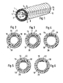
- the thin-walled, tight-fitting outer tube shows that the reinforcement is wound with a relatively small pitch, see gears 5 and 6.
- a second inner tube 7 is arranged within the first inner tube, which is fixed to the first inner tube with the exception of the area of a pocket 8 connected is.
- the large pitch angle of the pocket results from its interrupted boundary lines 9 and 10.
- the pocket which in the original state is laid flat along the circumference of the hose, see also FIGS. 2 and 3 to be discussed below, is elastically stretchable in the direction of the hose interior by the three energy conductors shown 11, 12 and 13 record. With a larger or smaller number of energy conductors, the limited elastic pocket is more or less stretched, but at least if an elastomeric material is preferred for the second inner tube, only to the extent that the cross sections of the energy conductors require.
- the energy conductors 11, 12, 13 are preferably only in each case with two outer linear contact points on the inside of the pocket, so that they are held essentially in the radial direction of the hose, but are movable to a certain extent in the circumferential direction in the pocket.
- the hose with the three energy conductors placed in the bag thus remains relatively flexible.
- the longitudinal axis of the hose which is just shown, but is flexible in its entirety, is indicated by 14.
- the hose cross sections according to FIGS. 2-6 are shown enlarged;
- the inner tubes and the outer tube are thin-walled, too.
- a second inner hose 16 rests on the inside of a first inner hose 15 with the exception of a region which forms an elastic pocket 17.
- the first inner tube and the second inner tube are connected to one another outside the region of the elastic pocket 17.
- Reinforcement is over the first inner tube consisting of a relatively stiff band 18 and a wire 19 wound helically.
- the slope of the band 18 and the wire 19 is small, as shown in Fig. 1, while the flexible pocket 17 running in the direction of the longitudinal axis runs with a greater slope.
- the hose is closed off from the outside by an outer hose 20 which lies closely against the band 18 and the wire 19.
- the embodiment of the flexible hose according to FIG. 3 differs from that according to FIG. 2 in that there is a continuous separating film 21 in the elastic pocket 17. Because of this separating film, the pocket for inserting energy conductors can be stretched elastically, i.e. be widened in the direction of the longitudinal axis, although during the production of the flexible hose the first and / or the second inner hose are also connected over the entire surface in order to connect the two inner hoses to one another outside the region of the pocket.
- the pocket which is elastically stretchable in the direction of the hose interior, is formed not only by a gap between the first inner hose and a second inner hose, but by a flat, thin-walled elastic receiving hose 22, which likewise consists of a thermoplastic or elastomeric material and can be stretched to the inside of the flexible hose, ie to the longitudinal axis.
- the shape of the flattened thin-walled receiving tube which is adapted to the curvature of the first inner tube so that an outer side can be attached to the first inner tube, can be seen from FIGS. 4-6.
- the receiving hose 22 is in turn coiled with a large slope, on the outside on the first inner hose and below the helical reinforcement consisting of the band 18 and the wire 19.
- the receiving hose is in the embodiment according to FIG. 4 at the points where it lies on the inside of the reinforcement, at least firmly connected to the tape.
- the receiving hose 22 is arranged between the first inner hose 15 and the second inner hose 16, which is also present here, and is connected to the outer sides of the two hoses with these. If at least one energy conductor is inserted into the receiving hose, the receiving hose essentially elastically stretches inwards together with the second inner hose to the longitudinal axis of the hose, since the outer circumference of the hose is essentially held in place by the reinforcement.
- FIG. 6 it is shown how the receiving hose is fastened to the inner wall of the first inner hose, while a second inner hose is dispensed with.
- the receiving tube will deform almost exclusively inwards to the longitudinal axis of the tube.
- the clear passage space of the flexible hose is the least of all the embodiments shown here, namely only reduced by the receiving hose itself and the energy conductor possibly contained in it.
- FIGS. 2-6 are shown in the state in which the flexible hose is supplied to the user by the hose manufacturer can, while the state shown in Fig. 1 can only be brought about by the user by inserting the energy conductors 11-13.
- the hose can also be provided with the energy conductors in the course of hose production if the desired equipment is determined and can be delivered in containers.
Landscapes
- Engineering & Computer Science (AREA)
- General Engineering & Computer Science (AREA)
- Mechanical Engineering (AREA)
- Rigid Pipes And Flexible Pipes (AREA)
- Electric Vacuum Cleaner (AREA)
Applications Claiming Priority (2)
| Application Number | Priority Date | Filing Date | Title |
|---|---|---|---|
| DE19873705292 DE3705292C1 (de) | 1987-02-19 | 1987-02-19 | Flexibler Schlauch |
| DE3705292 | 1987-02-19 |
Publications (2)
| Publication Number | Publication Date |
|---|---|
| EP0279344A2 true EP0279344A2 (fr) | 1988-08-24 |
| EP0279344A3 EP0279344A3 (fr) | 1990-06-06 |
Family
ID=6321327
Family Applications (1)
| Application Number | Title | Priority Date | Filing Date |
|---|---|---|---|
| EP88101938A Withdrawn EP0279344A3 (fr) | 1987-02-19 | 1988-02-10 | Tuyau flexible |
Country Status (3)
| Country | Link |
|---|---|
| EP (1) | EP0279344A3 (fr) |
| JP (1) | JPS63297889A (fr) |
| DE (1) | DE3705292C1 (fr) |
Cited By (4)
| Publication number | Priority date | Publication date | Assignee | Title |
|---|---|---|---|---|
| WO1993022108A1 (fr) * | 1992-04-30 | 1993-11-11 | Siemens Aktiengesellschaft | Dispositif tubulaire mobile |
| WO1999046529A1 (fr) * | 1998-03-11 | 1999-09-16 | Novoplastic | Conduit detectable en matiere synthetique et ses moyens de raccordement |
| EP1249200A1 (fr) * | 2001-04-11 | 2002-10-16 | Seb S.A. | Tuyau flexible gonflable pour aspirateur |
| WO2016132053A1 (fr) * | 2015-02-20 | 2016-08-25 | Societe Plymouth Francaise | Canalisation équipée d'un élément de détection |
Families Citing this family (4)
| Publication number | Priority date | Publication date | Assignee | Title |
|---|---|---|---|---|
| JPH0257786A (ja) * | 1988-08-23 | 1990-02-27 | Tigers Polymer Corp | 可撓性ホース |
| JP4205697B2 (ja) * | 2005-07-05 | 2009-01-07 | 京和工業株式会社 | 可撓性耐油液ホース |
| CN101994485B (zh) * | 2010-10-22 | 2014-04-30 | 河北华宏广源橡塑有限公司 | 热塑性采油输送管系统 |
| DE102016104558B4 (de) * | 2016-03-12 | 2022-07-07 | Fischer Rohrtechnik Gmbh | Rohrsystem |
Family Cites Families (6)
| Publication number | Priority date | Publication date | Assignee | Title |
|---|---|---|---|---|
| DE6926613U (de) * | 1969-07-03 | 1969-10-16 | Vorwerk & Co Elektrowerke Kg | Schlauch, insbesondere fuer staubsauger. |
| BE793596A (fr) * | 1972-01-03 | 1973-05-02 | Dayco Corp | Tuyau souple en matiere elastomere, notamment pour aspirateurs |
| US3780208A (en) * | 1972-06-05 | 1973-12-18 | Moore & Co Samuel | Composite hose having a grounding wire enclosed in a sleeve and wrapped about the core tube of the hose |
| SE7401692L (fr) * | 1974-02-08 | 1975-08-11 | Electrolux Ab | |
| SE7600738L (sv) * | 1976-01-26 | 1977-07-27 | Electrolux Ab | Dammsugarslang |
| US4368348A (en) * | 1979-12-21 | 1983-01-11 | Techno-Chemie Kessler & Co. Gmbh | Vacuum cleaner hose with an electrical conductor |
-
1987
- 1987-02-19 DE DE19873705292 patent/DE3705292C1/de not_active Expired
-
1988
- 1988-02-10 EP EP88101938A patent/EP0279344A3/fr not_active Withdrawn
- 1988-02-19 JP JP63035438A patent/JPS63297889A/ja active Pending
Cited By (8)
| Publication number | Priority date | Publication date | Assignee | Title |
|---|---|---|---|---|
| WO1993022108A1 (fr) * | 1992-04-30 | 1993-11-11 | Siemens Aktiengesellschaft | Dispositif tubulaire mobile |
| WO1999046529A1 (fr) * | 1998-03-11 | 1999-09-16 | Novoplastic | Conduit detectable en matiere synthetique et ses moyens de raccordement |
| FR2776135A1 (fr) * | 1998-03-11 | 1999-09-17 | Novoplastic Sa | Conduit associe a un conducteur electrique de detection, par exemple pour le tirage ou poussage d'un cable |
| EP1249200A1 (fr) * | 2001-04-11 | 2002-10-16 | Seb S.A. | Tuyau flexible gonflable pour aspirateur |
| FR2823431A1 (fr) * | 2001-04-11 | 2002-10-18 | Seb Sa | Tuyau flexible gonflable pour aspirateur |
| WO2016132053A1 (fr) * | 2015-02-20 | 2016-08-25 | Societe Plymouth Francaise | Canalisation équipée d'un élément de détection |
| FR3033017A1 (fr) * | 2015-02-20 | 2016-08-26 | Plymouth Francaise Sa | Canalisation equipee d’un element de detection |
| US10527194B2 (en) | 2015-02-20 | 2020-01-07 | Societe Plymouth Francaise | Piping equipped with a sensing member |
Also Published As
| Publication number | Publication date |
|---|---|
| JPS63297889A (ja) | 1988-12-05 |
| EP0279344A3 (fr) | 1990-06-06 |
| DE3705292C1 (de) | 1988-07-21 |
Similar Documents
| Publication | Publication Date | Title |
|---|---|---|
| DE69527528T2 (de) | Verfahren und vorrichtung zum herstellen von flexiblen schläuchen mit schraubenförmig gewickeltem heizwiderstand | |
| DE3633021C2 (fr) | ||
| EP0913165B1 (fr) | Construction de cathéter d'éversion | |
| EP0552429B1 (fr) | Endoscope avec une extrémité distale dirigeable | |
| DE10113208B4 (de) | Biegsame Welle zur Übertragung von Drehbewegung | |
| DE2758463B2 (de) | Endoskop mit flexiblem Endabschnitt und Krümmungseinrichtung dafür | |
| DE4115419A1 (de) | Flexibles rohr fuer ein endoskop und verfahren zu dessen herstellung | |
| EP3984106B1 (fr) | Guidage de câbles compact pour applications en salles blanches, et procédé de fabrication et unité de gainage associés | |
| EP0231504B1 (fr) | Pièce auxiliaire pour un tube de conduite de câbles | |
| EP0742399B1 (fr) | Tuyaux avec au moins une ligne de transmission d'énergie sans contrainte de traction | |
| DE69404196T2 (de) | Vorrichtung zum Tragen einer elastischen Muffe und durch eine entfernbare Tragvorrichtung in ausgedehntem Zustand gehaltene elastische Muffe | |
| DE3705292C1 (de) | Flexibler Schlauch | |
| DE3441040A1 (de) | Verbindungsschlauch | |
| DE3405552C2 (de) | Kunststoff-Schutzrohr | |
| WO2004066464A1 (fr) | Gaine de cable extensible et pouvant etre suspendue, constituee d'au moins un element gaine de cable | |
| EP0664988B1 (fr) | Tuyau téléscopique d'aspirateur avec conducteur électrique en spirale | |
| EP0235576B1 (fr) | Assemblage fermé et flexible de tubes | |
| DE2042183A1 (de) | Biegsame Stroemungsmittelleitung | |
| DE4121137C3 (de) | Verbindungseinrichtung mit einem nach Art einer Uhrfeder angeordnetem elektrischen Kabel | |
| DE69406533T2 (de) | Vorgestreckter elastomerer gegenstand | |
| EP4329575A1 (fr) | Tuyau flexible, en particulier tuyau d'aspirateur | |
| EP0699616A2 (fr) | Bobine à deux chambres | |
| DE202004002132U1 (de) | Vorrichtung zur Inspektion von Kanälen mit einem kurvenlenkbaren Biegemodul | |
| DE3390424T1 (de) | Leichter stromführender Schlauch | |
| DE3518013A1 (de) | Flexibler schlauch |
Legal Events
| Date | Code | Title | Description |
|---|---|---|---|
| PUAI | Public reference made under article 153(3) epc to a published international application that has entered the european phase |
Free format text: ORIGINAL CODE: 0009012 |
|
| AK | Designated contracting states |
Kind code of ref document: A2 Designated state(s): DE ES FR GB IT SE |
|
| PUAL | Search report despatched |
Free format text: ORIGINAL CODE: 0009013 |
|
| RHK1 | Main classification (correction) |
Ipc: F16L 11/11 |
|
| AK | Designated contracting states |
Kind code of ref document: A3 Designated state(s): DE ES FR GB IT SE |
|
| RAP1 | Party data changed (applicant data changed or rights of an application transferred) |
Owner name: EX-O-FLEX GESELLSCHAFT FUER KUNSTSTOFFORMUNG MBH Owner name: VOHRAN PATENTVERWERTUNGS-GMBH |
|
| 17P | Request for examination filed |
Effective date: 19901203 |
|
| 17Q | First examination report despatched |
Effective date: 19910523 |
|
| STAA | Information on the status of an ep patent application or granted ep patent |
Free format text: STATUS: THE APPLICATION IS DEEMED TO BE WITHDRAWN |
|
| 18D | Application deemed to be withdrawn |
Effective date: 19911203 |