EP0279355B1 - Système de télémaintenance pour un réseau de communication numérique - Google Patents
Système de télémaintenance pour un réseau de communication numérique Download PDFInfo
- Publication number
- EP0279355B1 EP0279355B1 EP88101997A EP88101997A EP0279355B1 EP 0279355 B1 EP0279355 B1 EP 0279355B1 EP 88101997 A EP88101997 A EP 88101997A EP 88101997 A EP88101997 A EP 88101997A EP 0279355 B1 EP0279355 B1 EP 0279355B1
- Authority
- EP
- European Patent Office
- Prior art keywords
- serious
- data
- cmoc
- fault
- alarm
- Prior art date
- Legal status (The legal status is an assumption and is not a legal conclusion. Google has not performed a legal analysis and makes no representation as to the accuracy of the status listed.)
- Expired - Lifetime
Links
Images




Classifications
-
- H—ELECTRICITY
- H04—ELECTRIC COMMUNICATION TECHNIQUE
- H04Q—SELECTING
- H04Q11/00—Selecting arrangements for multiplex systems
- H04Q11/04—Selecting arrangements for multiplex systems for time-division multiplexing
- H04Q11/0421—Circuit arrangements therefor
-
- H—ELECTRICITY
- H04—ELECTRIC COMMUNICATION TECHNIQUE
- H04M—TELEPHONIC COMMUNICATION
- H04M3/00—Automatic or semi-automatic exchanges
- H04M3/22—Arrangements for supervision, monitoring or testing
- H04M3/24—Arrangements for supervision, monitoring or testing with provision for checking the normal operation
- H04M3/244—Arrangements for supervision, monitoring or testing with provision for checking the normal operation for multiplex systems
Definitions
- the present invention relates to a remote maintenance system for a digital communication network consisting of a plurality of digital switching offices.
- a digital communication network comprises a plurality of local switching offices (LOs) and a toll center (TC), and recently, the maintenance of equipments at each LO is remotely executed at a centralized maintenance and operation center (CMOC) located at the TC.
- CMOC maintenance and operation center
- the maintenance system of thus using the CMOC will be called a remote maintenance system hereinafter.
- the CMOC has two functions: a maintenance function and an operation function.
- the operation function is for the administration of the network such as setting or changing subscribers, so that only the maintenance function at the CMOC will be discussed in this disclosure.
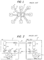
- FIGs. 1 and 2 A first remote maintenance system of the prior art will be discussed referring to Figs. 1 and 2.
- the supervisory information at each LO 1 is sent to the CMOC 3 through an exclusive data line (DL) 41 provided independently from a digital transmission line (DTL) 51 for ordinary communication in the digital communication network.
- DL exclusive data line
- DTL digital transmission line
- the operating status data and alarm data at the LO are gathered at an alarm unit (ALM) 10. Then, these data are sent to an data sending unit (SND) 16 through a bus line 100 in the LO, and are sent to the CMOC 3 through the DL 41.
- SND data sending unit
- the data for the operating status and alarm sent from the LO 1 are received at a data receiving unit (RCV) 36 in the CMOC 3. Then, in the CMOC 3, the data received at the RCV 36 are processed by a main processor (MPR) 31, displayed on a visual display unit (VDU) 351 of a system control work station (SCWS) 35, and stored in a memory means such as a magnetic tape (MT) 34.
- MPR main processor
- VDU visual display unit
- SCWS system control work station
- MT magnetic tape
- VDU visual display unit
- the operator at the LO 1 When the operator at the LO 1 receives the maintenance information for repairing the fault from the operator at the CMOC 3, the operator at the LO 1 repairs the fault at the LO 1 in accordance with the maintenance information from the operator at the CMOC 3.
- the operator at the LO 1 executes the maintenance to the fault in accordance with the maintenance information by observing a VDU 151 and operating an operating console 152 of the SCWS 35 at the LO 1.
- the data of the operating status and alarm at the LOs 1 are remotely supervised at the CMOC 3.
- the operator at the CMOC 3 must call the operator at the LO 1 to inform how to repair the fault
- the operator must be always stood by at each LO 1 for executing the maintenance
- the MT 14 also must be provided at the LO 1 for, e.g. initial programming to the serious fault such as a system-down in the LO 1.
- the system-down is a system trouble that the switching operation ceases due to a hard trouble of the switching network or a soft trouble in the main processor.
- hard trouble mostly occurs because of a trouble of the software for the main processor.
- the MT 14 is provided for storing an initial loading program used for normally restarting the switching network and/or the main processor.
- Reference symbols DTs 13 and 33 in Fig. 2 indicate digital terminals of the DL 51 provided between the LO 1 and the CMOC 3.
- a second remote maintenance system has been proposed in the prior art as shown in Figs. 3 and 4.
- the same numerals and symbols as in Figs. 1 and 2 designate the same units or functions as in Figs. 1 and 2.
- the maintenance data from the CMOC 3 are sent to respective LO 1 also through the exclusive data line.
- a one dot chain line having reference numeral 42 indicates that the data are transmitted in both ways between each LO 1 and the CMOC 3.
- the maintenance data from the CMOC 3 is transferred to the LO 1 through another DL 422.
- the operator at the CMOC 3 provides the maintenance data for the LO 1 by operating an operating console 352, observing a VDU 351 of a SCWS 35.
- the maintenance data made by the operator at the CMOC 3 is sent from an SND 37 in the CMOC 3 to an RCV 17 in the LO 1 through the DL 422.
- the second remote maintenance system of the prior art has the following merits compared with the first remote maintenance system of the prior art: 1) there is no necessity to use the telephone to send the maintenance data from the CMOC 3 to the LO 1; second, 2) there is no necessity to make the operator always stand by at the LO 1, and 3) there is no necessity to provide the MT because the initial loading to overcome the system-down can be executed by the maintenance data sent from the CMOC 3 through the DL 422.
- the merits 2) and 3) contribute to reduce the maintenance costs for the network.
- the second remote maintenance system has a demerit that the exclusive data lines (DLs) 41 and 422 are necessary, which causes an increase in the facility costs and the running costs for the DLs 41 and 422.
- a fourth remote maintenance system of the prior art which uses the DTL 51 for transferring the operating status and alarm data from the LO 1 to the CMOC 3.
- This sytem has been disclosed in "CENTRALIZED SUPERVISORY SYSTEM" , U.S. Patent 4,575,839 to Yusuke Ogata et al., in Mar. 11, 1986.
- Figs. 5 and 6 illustrate the system of Ogata as the third remote maintenance system of the prior art.
- the fourth system of the prior art of Ogata the operating status and alarm data from the LO 1 to the CMOC 3 are transferred through some channels of the DTL 51.
- the DTL 51 transfers the data under a pulse code modulation (PCM) system.
- PCM pulse code modulation
- One dot chain lines 43 in Figs. 5 and 6 indicate the channels.
- the operating status and the alarm information in LO 1 are gathered at the ALM 10, and the data of the information are created at the ALM 10 and sent to a common channel signaling equipment (CSE) 18 through a bus line 100.
- CSE common channel signaling equipment
- the data are sent, under an ordinary common channel signaling system, to the NW 12 through an interface unit (INT) 19.
- the ordinary common channel signaling system is, as well known, the very peculiar system used in the recent digital switching system.
- the operating status and alarm data are sent to the CMOC 3 through the NW 12 and the DT 13 in the LO 1 and the DTL 51 by using the channels 43.
- the operating status and alarm data are sent to the MPR 31 through an NW 32, an INT 36 and a CSE 37, and processed in the MPR 31 so that the operating status and alarm data are stored in the MT 34 and displayed on a VDU in the SCWS 35.
- the INT 36 is an interface between the NW 32 and the CSE 37, and the CSE 37 is for sending data and signals under the common channel signaling system.
- the exclusive data line becomes unnecessary to transmit the operating status and alarm data from the LO to the CMOC.
- the maintenance data from CMOC 3 to the LO 1 cannot be transmitted through the DTL 51. Accordingly, an operator must be stationed at the LO 1 and the MT also must be provided at the LO 1, which is functionally similar to the case of the first remote maintenance system of the prior art.
- an object of the present invention is to reduce the operators at local offices of the digital communication network having a remote maintenance system, for reducing the personnel expenses.
- Another object of the present invention is to eliminate the exclusive data line for transmitting the alarm data and the maintenance data between each local office (LO) and the centralized maintenance and operation center (CMOC) of the remote maintenance system, for reducing the facilities costs of the network.
- LO local office
- CMOC centralized maintenance and operation center
- Still another object of the present invention is to eliminate the data storing means such as a magnetic tape unit to store the program for the initial loading, from each LO, for reducing the facilities costs in each LO and the running costs thereof.
- Still more another object of the present invention is to execute the maintenance to the serious faults such as the system-down in the LO, without the operator and the data storing means at the LO.
- Still another object of the present invention is to make the CMOC acknowledge that LO which has a serious fault when the LO having the serious fault is located far from the CMOC through many tandem offices.
- the above objects of the present invention are achieved by performing the following matters: 1) transmitting the operating status and alarm data from each LO to the CMOC through the ordinary digital transmission line (DTL); 2) transmitting the maintenance data from the CMOC to each LO through the DTL; 3) applying No. 7 Common Channel Signaling System (CCS) recommended by International Brass and Telephone Consultative Committee (CCITT) to the transmission of the alarm and the maintenance data between each LO and the CMOC; 4) grouping all LOs into several groups so that each group has at least two LOs; and 5) providing local exclusive data lines among the LOs in each group for executing the backup to each other when one of the LOs in the group has a serious fault.
- CCS Common Channel Signaling System
- CITT International Telegraph and Telephone Consultative Committee
- the personnel expenses and the facilities costs at the LO can be reduced.
- the transmission of the alarm data from the LO to the CMOC and of the maintenance data from the CMOC to the LO can be made easily, and the location of the LO having the serious fault can be easily found.
- the transmission can be made easily, and the location of the LO having the serious fault can be found easily.
- the maintenance of the serious faults such as the system-down at the LO can be executed without the operator and the data storing means at the LO.
- the switching network at the first LO cannot be used, so that the data transmission through the DTL between the first LO and the CMOC becomes impossible to be executed.
- the alarm data at the first LO can be transmitted to the CMOC through the local exclusive data line, another second LO connected to the first LO by the local exclusive data line, and the DTL between the second LO and the CMOC.
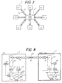
- the expenses of the exclusive data lines, such as DLs 41 and 422 in Fig. 4, can be reduced to zero by transmitting not only the alarm data from the LO 1 to the CMOC 3 but also the maintenance data from the CMOC 3 to the LO 1 through the DTL 51 as shown in Figs. 7 and 8.
- the same reference numerals and symbols as in Figs. 5 and 6 designate the same units or function as in Figs. 5 and 6.
- reference numeral 43 indicates the data transmission with which the alarm data and the maintenance data can be transmitted in both ways between the LO 1 and the CMOC 3.
- the network had such remote maintenance system as shown in Figs. 7 and 8, the system could not execute the maintenance to the serious fault such as system-down, because , the NW 12 in the LO 1 cannot be used under the system-down, so that the alarm and maintenance data cannot be transmitted between the LO 1 and the CMOC 3.
- the above problem in the remote maintenance system shown in Figs. 7 and 8 can be solved by remote maintenance systems embodying the present invention, shown in Fig. 9.
- the remote maintenance systems embodying the present invention include two systems: a first system and a second system.
- Figs. 11 and 12 and Figs. 13 and 14 illustrate the first and the second system respectively.
- the same numeral or symbol as in Figs. 7 and 8 designates the same unit or function as in Figs. 7 and 8
- Figs. 13 and 14 the same numeral or symbol as in Figs. 11 and 12 designates the same unit or function as in Fig. 11 and 12.
- the alarm and the maintenance data are usually transmitted between the LO and the CMOC respectively by using the DTL 51, which is similar to the system in Figs. 7 and 8; however, the systems embodying the present invention differ from the system in Figs. 7 and 8, as follows: the LOs respectively connected to the CMOC through the DTL 51 are grouped so that each group includes two (or more) LOs, and in each group, the two LOs, (or two LOs adjacent to each other in case that more than two LOs are grouped), are connected by a local data line (LDL) 44 as shown in Fig. 9.
- LDL local data line
- This connection by the LDL 44 is for performing the backup of the LOs connected to each other when a serious fault such as system-down occurs at one of the grouped LOs. For instance, when an LO (a first LO) has the serious fault, another LO (a second LO) connected with the first LO performs the backup the first LO by transmitting the fault information from the first LO to the CMOC and the maintenance information from the CMOC to the first LO by using the switching function of the second LO.
- the difference between the first system and the second system is as follows: in the first system, when the serious fault occurs at the first LO, the maintenance data from the CMOC to the first LO are transmitted through the DTL (first DTL) between the first LO and the CMOC, and the LDL is used for transmitting the alarm information from the first LO to the CMOC; in the second system, when the serious fault occurs at the first LO, not only the alarm information from the first LO but also the maintenance data from the CMOC to the first LO are transmitted through the DTL connecting the second LO and the CMOC and the LDL.
- LOs 1-1 and 1-2 are grouped; and in the second system shown in Figs. 13 and 14, LOs 1-3 and 1-4 are grouped.
- Figs. 11 and 13 illustrate the relationship of the data link among the grouped LOs and the CMOC
- Figs. 12 and 14 illustrate the details of one of the grouped LOs.
- a second point of the present invention is to use No. 7 CCS for transmitting the alarm information and the maintenance data through the switching network in the backup LO and the DTL connecting the backup LO to the CMOC.
- this data transmission in the centralized maintenance system becomes very simple even though tandem offices (TOs) exist on the way of a route from an LO 1 to the CMOC 3 as shown in Fig. 10.
- TOs tandem offices
- reference numerals 21, 22 and 23 indicate the TOs, and other numerals and symbols designate the same offices and function as in Fig. 9.
- the transmission route for the alarm and maintenance data through the TO 22 is occupied by other transmitting signals, the data can be transmitted through the TO 23, which is owe to the No. 7 CCS system.
- Figs. 11 and 12 illustrate the first remote maintenance system embodying the present invention.
- Fig. 11 illustrates the relationship between the grouped LOs and the CMOC
- the Fig. 12 illustrates the details of an LO (LO 1-1) being one of the grouped LOs in Fig. 11.
- the same reference numeral as in Fig. 8 designates the same unit or function as in Fig. 8.
- the supervisory data and the ordinary alarm signal in a first LO (LO 1-1) and a second LO (LO 1-2 are sent to the CMOC through the DTLs 511 and 512 with the operation of the NWs 12 in the LOs 1-2 and 1-2 respectively.
- a serious alarm signal which is a ground signal for informing that the serious fault occurs in the LO, is outputted from the MPR 11 in the LO 1-1.
- the NW 12 in the LO 1-1 cannot be used. Accordingly, in the first system embodying the present invention, the serious alarm signal is sent to the LO 1-2 through the LDL 441.
- the LO 1-2 sends the serious alarm signal to the CMOC through the DTL 512 and at the same time controls the LO 1-1 so that the maintenance data, for repairing the serious fault in the LO 1-1, sent from the CMOC can be received without using the NW 12 in the LO 1-1.
- an alarm control unit (ALMCU) 101 and a loader (LD) 20 are newly provided in each LO.
- Fig. 12 illustrates the detail function in the LO 1-1.
- the supervisory information and the ordinary fault information which are obtained by an ordinary fault detector 102, are gathered to the ALMCU 101 and controlled the MPR so that the ordinary alarm signal is sent to the CSE 18 through a serial information adapter (SIA) 25 and the bus line 100.
- the supervisory information and the ordinary alarm signal arrived at the SIA 25 are modified so as to be sent to the CMOC under the No. 7 CCS system through the INT 19 and the NW 12 by the operation of the MPR 11, and through the LD 20, the DT 13 and the DTL 511.
- the maintenance data for repairing the ordinary fault in the LO 1-1 are provided by the operator at the CMOC and sent to the LO 1-1 through the DTL 511.
- the maintenance data arrived at the LO 1-1 are fed to the NW 12 through the DT 13 and the LD 20 and sent to the CSE 18.
- the maintenance data sent from the CMOC under the No. 7 CCS system are changed to the regular data at the CSE 18 and sent to the MPR 11 in which the ordinary fault is repaired.
- a serious alarm signal due to the serious fault is sent from an emergency action/control unit (EMA) 111 in the MPR 11 to an alarm exterior terminal (ALEXT) 21 through a line L1 in the LO 1-1.
- EMA emergency action/control unit
- ALERT alarm exterior terminal
- the first alarm signal is also sent to an alarm indicator panel unit (ALIPU) 22 in the LO 1-1 by which the occurrence of the serious fault is indicated.
- ALIPU alarm indicator panel unit
- the first alarm signal from the ALEXT 21 in the LO 1-1 is sent to the ALEXT 21 in the LO 1-2 through the LDL 441.
- the LO 1-2 has the same construction and function as those of the LO 1-1 and operates normally in this explanation.
- the first alarm signal arrived at the ALEXT 21 in the LO 1-2 is fed to the ALMCU 101 in the LO 1-2 along a line (L) 2 as shown in the LO 1-2 in Fig. 11; the details of the above may be realized in Fig. 12 by imagining that Fig. 12 were for the LO 1-2.
- the L2 consists of a plurality of lines, which means that the L2 includes other serious alarm signals wich will be stated later.
- the ALMCU 101 in the LO 1-2 When the ALMCU 101 in the LO 1-2 receives the first alarm signal, the ALMCU 101 outputs an LD control signal and sends it to the ALEXT 21 in the LO 1-2 through a line (L) 3.
- the LD control signal passing through the ALEXT 21 in the LO 1-2 is sent to the ALEXT 21 in the LO 1-1 through the LDL 441 as shown in Fig. 11.
- the LD control signal passing through the ALEXT 21 in the LO 1-1 is fed to the LD 20 through a line (L) 4. Then the LD 20 operates so that the connection from the DTL 511 to the NW 12 through the DT 13 is changed toward the EMR 111 in the MPR 11 through a CSE 24.
- a route L10 - L11 is changed to a route L10 - L12; wherein, the L10 is a line connecting the DT 13 with the LD 20, the L11 is a line connecting the LD 20 with the NW 12 and the L12 is a line connecting the LD 20 with the CSE 24 as shown in Fig. 12.
- the first alarm signal from the EMA 111 is a simple ON-OFF signal, which is usually called a "ground signal" for only alarming that a serious fault occurs in the LO 1-1. Therefore, the detail data of the serious fault cannot be sent to the CMOC 3 by the first alarm signal.
- the serious alarm data can be sent from the EMA 111 to the CMOC through the route L12 - L10 and the DTL 511, so that the serious fault in the LO 1-1 can be analyzed by the operator at the CMOC 3, and the maintenance data for repairing the serious fault can be sent back to the EMR 111 in the LO 1-1 through the same route as the route through which the serious alarm data have been sent to the CMOC 3 from the LO 1-1.
- the serious fault is mainly due to the trouble of the software for operating the MPR 11.
- the EMA 111 is a unit for automatically detecting the fault in the MPR 11, and primarily sending the first alarm signal and secondly sending the serious alarm data in the LO 1-1 to the CMOC 3.
- an externally supervisory Equipment (ESE) 23 is one of the supervisory means.
- the ESE 23 is for automatically supervising the operation of the NW 12 including the operation of the MPR 11.
- the output, which is a serious fault signal, which will be called a second alarm signal hereinafter, from the ESE 23 is fed to the EMA 111.
- the second alarm signal is also sent to the ALIPU 22 for indicating that there is the second alarm signal in the LO 1-1.
- the first and second alarm signals relate to the system-down due to the MPR 11 and/or the NW 12; however, the system-down also occurs due to power-down in the LO 1-1.
- a power alarm unit (PAL) 26 is for detecting the power-down and producing a third alarm signal when the power-down occurs.
- the third alarm signal is sent to the ALEXT 21 through a line (L) 6 and also sent to the ALEXT 21 in the LO 1-2 through the LDL 441; wherein, in Fig. 11, the line for transmitting the third alarm signal is omitted to be depicted in the LDL 441.
- the third alarm signal passing through the ALEXT 21 in the LO 1-2 is fed to the ALMCU 101 through one line of the L2.
- the ALMCU 101 in the second LO operates so that the third alarm signal is transmitted to the CMOC 3 through the SIA 25, the bus line 100, the CSE 18, the INT 10, the NW 12, the LD 20, the DT 13, which are in the LO 1-2, and the DTL 512.
- the remote maintenance cannot be executed because the power in the LO 1-1 is down, so that an operator is sent to the LO 1-1 for repairing a power supply system, which is not depicted in Fig. 12, in the LO 1-1.
- the serious alarm signals sent to the LO 1-2 from the LO 1-1 are all the simple ground signals. Therefore, simple conductors such as bare wires can be applied to the LDL 441, which results in reducing the costs for the LDL 441.
- the costs of the lines for transmitting these alarm signals and also the maintenance data between the LO 1-1 and the CMOC 3 can be reduced.
- Figs. 13 and 14 are for explaining the relationship of the connection between the grouped LOs (LO 1-3 and LO 1-4) and the CMOC 3.
- Fig. 14 illustrates the details of one of the grouped LOs, for example, the LO 1-3.
- the second remote maintenance system embodying the present invention will be discussed under the assumption that the serious fault occurs in the LO 1-3 and the LO 1-4 performs the backup to the LO 1-3.
- the feature of the second remote maintenance system embodying the present invention is that the loader unit (LD) and the TDL 511 between the LO 1-3 and the CMOC 3 are not used for transmitting the serious alarm data and the maintenance data between the LO 1-3 and the CMOC, as done in the first remote maintenance system, and, instead of using the LD and the TDL 511, the serious alarm data sent from the LO 1-3 to the CMOC 3 and the maintenance data from the CMOC 3 to the LO 1-3 are transmitted through the DTL 512 between the LO 1-4 and the CMOC 3, the LO 104 and an LDL 442 between the LOs 1-3 and 1-4, as shown in Fig. 13.
- the loader unit (LD) and the TDL 511 between the LO 1-3 and the CMOC 3 are not used for transmitting the serious alarm data and the maintenance data between the LO 1-3 and the CMOC, as done in the first remote maintenance system, and, instead of using the LD and the TDL 511, the serious alarm data sent
- the first alarm signal from the EMA 111 is sent to the ALEXT 21 through the L1 in the LO 1-3. Then the first alarm signal from the ALEXT 21 in the LO 1-3 are sent to the ALMCU 101 in the LO 1-4 through the LDL 442, ALEXT 21 in the LO 1-4 and the L2 in the LO 1-4. This is the same as the case of the first remote maintenance system embodying the present invention.
- the ALMCU 101 in the LO 1-4 controls so that the serious alarm signal is sent to the CMOC 3 through the SIA 25, the bus line 100, the CSE 18, the INT 19, the NW 12, the DT 13, which are in the LO 1-4, and DTL 512. Then, as the CMOC 3, the operator at the CMOC 3 investigates the serious alarm signal from the LO 1-3 and sends the maintenance data for remotely repairing the serious fault in the LO 1-3.
- the maintenance data from the CMOC 3 are not sent to the LO 1-3 using the DTL 511 as the first system, they are sent to the LO 1-3 through the DTL 512, the LO 1-3 and the LDL 442. That is, the maintenance data arrived at the LO 1-4 are sent to a modem (MD) 28 in the LO 1-4 through the DT 18, the NW 12, the INT 19, the CSE 18, the bus line 100 and the SIA 27 in the LO 1-4.
- the maintenance data from the MD 28 in the LO 1-4 are sent to a modem (MD) 29 in the LO 1-3 through a high quality transmission line such as a coaxial cable, in the LDL 442.
- the maintenance data arrived at the MD 29 in the LO 1-3 are sent to the EMA 111 in the MPR 11 in the LO 1-3 so as to repair the serious fault.
- the high quality transmission line is used in the LDL 442 instead of providing the LD 20 in each LO as in the case of the first remote maintenance system.
- the PAL 26 produces a third alarm signal which is sent to the ALMCU 101 in the LO 1-4 and the third alarm signal is sent to the CMOC 3 through the same route as that in the case of the first or second alarm signal.
- the system-down occurs as the serious fault due to the fault in the MPR including the fault of the software, and a power-down is rare. Therefore, applying the first or second remote maintenance system of the present invention to the digital communication network, an operator is not required to be always stationed and the MT does not also need to be provided at each LO.
Landscapes
- Engineering & Computer Science (AREA)
- Computer Networks & Wireless Communication (AREA)
- Signal Processing (AREA)
- Data Exchanges In Wide-Area Networks (AREA)
- Maintenance And Management Of Digital Transmission (AREA)
- Monitoring And Testing Of Exchanges (AREA)
- Selective Calling Equipment (AREA)
Claims (14)
- Système de télémaintenance pour un réseau de communication, ledit système comprenant:
un central interurbain à commutation numérique (TC) comprenant un réseau à commutation numérique central fonctionnant selon le système de signalisation à voie commune (CCS) No7 recommandé par le Comité Consultatif International pour le Télégraphe et le Téléphone (CCITT);
une pluralité de centraux urbains à commutation numérique (LOs) comprenant chacun:
un réseau urbain à commutation numérique (NW) fonctionnant selon ledit système CCS No7,
un dispositif de détection de panne ordinaire pour détecter automatiquement une panne ordinaire se produisant dans ledit LO et fournissant un signal de panne ordinaire, ladite panne ordinaire étant une panne que ledit NW traite normalement lorsque ladite panne se produit dans ledit LO;
un dispositif de commande d'alarme comprenant une unité pour recevoir ledit signal de panne ordinaire et délivrant un signal d'alarme ordinaire, ledit signal d'alarme ordinaire étant un signal par lequel on indique l'occurrence de ladite panne ordinaire dans le ledit LO;
un dispositif de détection et de réparation d'une panne grave pour détecter automatiquement une occurrence de panne grave dans ledit LO, pour délivrer automatiquement un signal d'alarme grave et des données d'alarme grave et pour réparer ladite panne grave en fonction des données de maintenance (secondes données de maintenance) pour réparer ladite panne grave, ladite panne grave étant une panne par laquelle ledit NW tombe en panne, ledit signal d'alarme grave étant un signal par lequel on indique l'occurrence de ladite panne grave dans le LO et lesdites données d'alarme grave étant des données comportant des détails de ladite panne grave;
Une ligne de transmission (DTL) pour transmettre, entre chacun desdits LOs et ledit TC, des données et/ou des signaux concernant une communication ordinaire dans le réseau de communication numérique, pour transmettre ledit signal d'alarme ordinaire, ledit signal d'alarme grave et lesdites données de panne grave dudit LO audit TC, et pour transmettre des données de maintenance (premières données de maintenance) pour réparer ladite panne ordinaire et lesdites secondes données de maintenance dudit TC audit LO;
un centre d'exploitation et de maintenance centralisé (CMOC) situé audit TC et relié fonctionnellement à chacun desdits LOs via ledit TC et ledit DTL, pour réparer à distance ladite panne ordinaire en produisant et en envoyant lesdites premières données de maintenance audit LO lorsque ledit signal d'alarme ordinaire est envoyé dudit LO audit CMOC et pour réparer à distance ladite panne grave en produisant et en envoyant lesdites secondes données de maintenance audit LO lorsque ledit signal d'alarme grave et lesdites données d'alarme grave sont envoyées dudit LO audit CMOC;
une pluralité de groupes desdits LOs, chacun desdits groupes comprenant au moins deux LOs;
une ligne de données urbaine (LDL) reliée fonctionnellement aux deux LOs dans ledit groupe comprenant une ligne pour transmettre ledit signal d'alarme grave d'un LO (premier LO) desdits deux LOs audit CMOC via un autre LO (second LO) desdits deux LOs dudit groupe et ledit DTL (second DTL) reliant ledit second LO audit TC et ledit TC, lorsque ladite panne grave se produit dans ledit premier LO et ledit second LO fonctionne normalement et dans lequel chacun desdits LOs comprend en outre;
un dispositif d'envoi et de réception de données pour envoyer, selon ledit système No7 CCS, ledit signal d'alarme ordinaire audit CMOC et pour recevoir lesdites premières données de maintenance envoyées, selon ledit système CCS No7, dudit CMOC, respectivement via ledit NW dudit second LO, ledit DTL et ledit TC, lorsque ladite panne ordinaire se produit dans ledit LO, et pour envoyer, selon ledit système CCS No7, ledit signal d'alarme grave dudit premier LO audit CMOC et pour recevoir lesdites secondes données de maintenance envoyées, selon ledit système CCS No7, dudit CMOC, respectivement via ledit TC, ledit second DTL et ledit NW dudit second LO, lorsque ladite panne grave se produit dans ledit premier LO et ledit second LO fonctionne normalement. - Système de télémaintenance selon la revendication 1, ledit système comprenant en outre un dispositif de chargement pour changer une route continue à partir dudit DTL vers ledit LO de sorte que: ladite route relie ledit DTL audit NW lorsque ledit LO fonctionne normalement ou ladite panne ordinaire se produit dans ledit LO; et ladite route relie ledit DTL audit dispositif de détection et de réparation de panne grave lorsque ladite panne grave se produit dans ledit premier LO, ledit dispositif de chargement changeant ladite route de sorte que ledit DTL est relié audit dispositif de détection et de réparation de panne grave dans ledit premier LO par un signal de commande du dispositif de chargement envoyé par ledit second LO fonctionnant normalement.
- Système de télémaintenance selon la revendication 2 dans lequel:
ledit dispositif de commande d'alarme comprend en outre, dans ledit second LO, une unité pour fournir ledit signal de commande du dispositif de chargement pour la réception dudit signal d'alarme grave envoyé par ledit dispositif de détection et de réparation de panne grave dudit premier LO, lorsque ladite panne grave se produit dans ledit premier LO et le second LO fonctionne normalement; et
ledit LDL comprend en outre des lignes pour envoyer ledit signal d'alarme grave dudit dispositif de détection et de réparation de panne grave dudit premier LO audit second LO et pour envoyer ledit signal de commande du dispositif de chargement dudit second LO audit premier LO. - Système de télémaintenance selon la revendication 1 dans lequel:
ledit dispositif de commande d'alarme comprend, en outre dans ledit second LO, une unité pour faire ledit envoi de données et un dispositif de réception dudit second LO envoie ledit signal grave et lesdites données de panne grave, envoyés dudit premier LO, audit CMOC, et pour faire ledit envoi de données et le dispositif de réception dudit second LO reçoit lesdites secondes données de maintenance dudit CMOC, lorsque ladite panne grave se produit dans ledit premier LO et ledit second LO fonctionne normalement; et
ledit LDL comprend en outre des lignes pour envoyer lesdites secondes données de maintenance reçues sur ledit second LO, dudit second LO audit premier LO, lorsque ladite panne grave se produit dans ledit premier LO et ledit second LO fonctionne normalement. - Système de télémaintenance selon la revendication 4, ledit système comprenant en outre:
un dispositif d'envoi de données, dans ledit second LO, pour envoyer lesdites secondes données de maintenance envoyées par ledit CMOC, audit dispositif de détection et de réparation de panne grave audit premier LO via ledit LDL, lorsque ladite panne grave se produit dans ledit premier LO et ledit second LO fonctionne normalement; et
un dispositif de réception de données, dans ledit premier LO, pour recevoir lesdites données de maintenance envoyées par ledit dispositif d'envoi de données dudit second LO via ledit LDL, lesdites données de maintenance reçues sur ledit dispositif de réception de données dudit premier LO étant appliquées audit dispositif de détection et de réparation de panne grave dudit premier LO, lorsque ladite panne grave se produit dans ledit premier LO et ledit second LO fonctionne normalement. - Système de télémaintenance selon la revendication 1, ledit système comprenant en outre un équipement de supervision externe (ESE) pour superviser le fonctionnement de commutation dudit NW, ledit ESE délivrant un signal de panne audit dispositif de détection et de réparation de panne grave, ledit dispositif de détection et de réparation de panne grave délivrant automatiquement ledit signal d'alarme grave et lesdites données d'alarme grave.
- Système de télémaintenance selon la revendication 2 comprenant en outre un second dispositif d'envoi et de réception de données, situé entre ledit dispositif de détection et de réparation de panne grave et ledit dispositif de chargement, pour envoyer des données d'alarme grave audit CMOC selon ledit système CCS No7 via ledit dispositif de chargement et pour recevoir lesdites secondes données de maintenance envoyée par ledit CMOC selon ledit système CCS No7 via ledit dispositif de chargement.
- Système de télémaintenance selon la revendication 3, ledit système comprenant en outre un dispositif d'alarme de mise hors tension (PAL) pour détecter qu'il s'est produit une panne de mise hors tension dans un LO (premier LO) desdits deux LOs dudit groupe et pour délivrer un signal d'alarme de mise hors tension dudit premier LO audit autre LO (second LO), fonctionnant normalement, desdits deux LOs dudit groupe.
- Système de télémaintenance selon la revendication 8 dans lequel:
ledit dispositif de commande d'alarme, dans ledit second LO, comprend en outre une unité pour recevoir ledit signal de mise hors tension envoyé par ledit premier LO et pour fournir ledit signal de commande du dispositif de chargement; et
ledit LDL comprend en outre une ligne pour envoyer ledit signal d'alarme de mise hors tension dudit premier LO audit dispositif de commande d'alarme dudit second LO. - Système de télémaintenance selon la revendication 5, ledit système comprenant en outre un dispositif d'alarme de mise hors tension (PAL) pour détecter qu'il s'est produit une panne de mise hors tension dans un LO (premier LO) desdits deux LOs dudit groupe et pour délivrer un signal d'alarme de mise hors tension dudit premier LO audit autre LO (second LO), fonctionnant normalement, desdits deux LOs dudit groupe.
- Système de télémaintenance selon la revendication 10, dans lequel:
ledit dispositif de commande d'alarme, dans ledit premier LO, comprend en outre une unité pour recevoir ledit signal d'alarme de mise hors tension et pour faire ledit envoi de données et le dispositif de réception envoie un signal d'alarme de mise hors tension audit CMOC; et
ledit LDL comprend en outre une ligne pour envoyer ledit signal d'alarme de mise hors tension dudit premier LO audit dispositif de commande d'alarme dudit second LO. - Système de télémaintenance pour un réseau numérique de communication, ledit système comprenant:
un central interurbain à commutation numérique (TC) comprenant un réseau à commutation numérique central
une pluralité de centraux urbains à commutation numérique (LOs) divisé en une pluralité de groupes de sorte que chaque groupe comprend au moins deux LOs, chaque LO dans ledit groupe comprenant un réseau urbain à commutation numérique (NW) un premier dispositif pour délivrer automatiquement un signal d'alarme grave et des données d'alarme grave lorsque une panne grave se produit dans ledit LO et pour réparer automatiquement ladite panne grave en utilisant des données de maintenance, ladite panne grave étant une panne par laquelle le fonctionnement de commutation dudit NW tombe en panne, ledit signal d'alarme grave étant un signal par lequel on indique l'occurrence de ladite panne grave dans le LO et lesdites données d'alarme grave étant des données détaillant ladite panne grave et lesdites données de maintenance étant des données pour réparer ladite panne grave;
un centre d'exploitation et de maintenance centralisé (CMOC) étant situé audit TC, pour donner une alarme à distance qu'une panne grave s'est produite dans ledit LO par la réception dudit signal d'alarme grave dudit LO et pour réparer à distance ladite panne grave dudit LO en fournissant et en envoyant lesdites données de maintenance audit LO lorsque ledit CMOC reçoit ledit signal d'alarme grave et/ou des données dudit LO;
un dispositif de ligne de transmission numérique (DTL) reliant respectivement ledit LO et ledit TC, pour effectuer une transmission de communication ordinaire dans le réseau de communication numérique, pour transmettre ledit signal d'alarme grave, lesdites données d'alarme grave, et lesdites données de maintenance entre ledit LO et ledit CMOC; et
un dispositif de ligne de données urbaine (LDL) reliant deux LOs dudit groupe, comprenant une ligne pour transmettre ledit signal d'alarme grave d'un (premier LO) desdits deux LOs dudit groupe audit CMOC via ledit autre LO (second LO) desdits deux LOs, ledit dispositif DTL reliant ledit second LO et ledit TC et ledit TC, lorsque ladite panne grave se produit dans ledit premier LO et ledit second LO fonctionne normalement - Système de télémaintenance selon la revendication 12, dans lequel:
ledit LO comprend en outre
un dispositif de raccordement pour relier ledit LO audit dispositif DTL,
un second dispositif pour envoyer lesdites données d'alarme dudit premier dispositif audit CMOC via le premier dispositif DTL, pour relier un (premier LO) desdits deux LOs dudit groupe, et ledit TC, et pour empêcher lesdites données d'alarme de passer via ledit NW dans ledit premier LO lorsque ladite panne grave se produit dans ledit premier LO et pour conduire lesdites données de maintenance reçue dudit CMOC audit premier dispositif via ledit premier dispositif DTL, pour empêcher lesdites données de maintenance de passer à travers ledit NW dans ledit premier LO lorsque ladite panne grave se produit dans ledit premier LO, en changeant la liaison dudit dispositif de raccordement audit NW en une liaison dudit dispositif de raccordement audit premier dispositif dudit premier LO, ledit changement étant effectué par un signal de commande du second dispositif reçu de l'autre (second LO) desdits deux LOs lorsque ledit second LO fonctionne normalement, et
un troisième dispositif, dans ledit second LO, pour fournir ledit signal de commande du second dispositif audit second dispositif dudit premier LO lorsque ladite panne grave se produit dans ledit premier LO, ledit second LO fonctionne normalement et ledit troisième dispositif dudit second LO reçoit ledit signal d'alarme dudit premier dispositif dans ledit premier LO; et
Ledit dispositif LDL comprend de plus, une ligne pour transmettre ledit signal de commande du second dispositif dudit troisième dispositif dudit second LO audit second dispositif dudit premier LO lorsque une panne grave se produit dans ledit premier LO et ledit second LO fonctionne normalement. - Système de télémaintenance selon la revendication 12, dans lequel:
ledit LO comprend en outre
un dispositif de réception de données, dans un (premier LO) desdits deux LOs dudit groupe, pour recevoir lesdites données de maintenance envoyées par ledit CMOC via ledit TC, le second DTL, reliant l'autre (second LO) desdits deux LOs et ledit TC, ledit second LO et ledit LDL, lorsque ladite panne grave se produit dans ledit premier LO et ledit second LO fonctionne normalement, lesdites données de maintenance reçues sur ledit dispositif de réception de données étant appliquées audit premier dispositif dudit premier LO, et
un dispositif d'envoi de données, dans ledit second LO, pour envoyer lesdites données de maintenance reçues, sur ledit second LO, dudit CMOC via ledit TC et ledit second DTL, audit dispositif de réception de données dudit premier LO via ledit LDL lorsque ladite panne grave se produit dans ledit premier LO et ledit second LO fonctionne normalement; et
ledit dispositif LDL comprend en outre une ligne pour transmettre lesdites données de maintenance dudit dispositif d'envoi de données dans ledit second LO audit dispositif de réception de données dudit premier LO lorsque ladite panne grave se produit dans ledit premier LO et ledit second LO fonctionne normalement.
Applications Claiming Priority (2)
| Application Number | Priority Date | Filing Date | Title |
|---|---|---|---|
| JP62033629A JPS63200699A (ja) | 1987-02-17 | 1987-02-17 | 遠隔保守制御方式 |
| JP33629/87 | 1987-02-17 |
Publications (3)
| Publication Number | Publication Date |
|---|---|
| EP0279355A2 EP0279355A2 (fr) | 1988-08-24 |
| EP0279355A3 EP0279355A3 (en) | 1990-08-08 |
| EP0279355B1 true EP0279355B1 (fr) | 1993-10-06 |
Family
ID=12391744
Family Applications (1)
| Application Number | Title | Priority Date | Filing Date |
|---|---|---|---|
| EP88101997A Expired - Lifetime EP0279355B1 (fr) | 1987-02-17 | 1988-02-11 | Système de télémaintenance pour un réseau de communication numérique |
Country Status (5)
| Country | Link |
|---|---|
| US (1) | US4870638A (fr) |
| EP (1) | EP0279355B1 (fr) |
| JP (1) | JPS63200699A (fr) |
| CA (1) | CA1281799C (fr) |
| DE (1) | DE3884638T2 (fr) |
Families Citing this family (16)
| Publication number | Priority date | Publication date | Assignee | Title |
|---|---|---|---|---|
| US4949246A (en) * | 1988-06-23 | 1990-08-14 | Ncr Corporation | Adapter for transmission of data words of different lengths |
| DE3833212A1 (de) * | 1988-09-30 | 1990-04-05 | Bosch Gmbh Robert | Antiblockierregelsystem |
| DE3906334A1 (de) * | 1989-02-28 | 1990-09-06 | Standard Elektrik Lorenz Ag | Uebertragungsnetz mit schaltbaren netzknoten |
| US5307354A (en) * | 1991-05-31 | 1994-04-26 | International Business Machines Corporation | Method and apparatus for remote maintenance and error recovery in distributed data processing networks |
| US5319775A (en) * | 1991-07-22 | 1994-06-07 | Ncr Corporation | Centralized diagnostic system for loosely coupled processors |
| CA2078081A1 (fr) * | 1992-09-11 | 1994-03-12 | Mitel Knowledge Corporation | Methode pour tenir au courant des evenements les noeuds d'un reseau a circuits commutes |
| JPH06214897A (ja) * | 1992-12-14 | 1994-08-05 | E Syst Inc | 誤り状態検出時に周辺装置に記憶したデータの損失を最少にする方法 |
| US6768787B1 (en) | 1993-02-16 | 2004-07-27 | C & P Of Virginia | Common channeling signaling network maintenance and testing |
| US5457729A (en) * | 1993-03-15 | 1995-10-10 | Symmetricom, Inc. | Communication network signalling system link monitor and test unit |
| US5473596A (en) * | 1993-12-09 | 1995-12-05 | At&T Corp. | Method and system for monitoring telecommunication network element alarms |
| KR0164411B1 (ko) * | 1994-12-28 | 1999-01-15 | 윤종용 | 원격안전 관리시스템의 유지보수를 위한 경보처리방법 및 장치 |
| US5793946A (en) * | 1996-03-12 | 1998-08-11 | Varis Corporation | Run-time diagnostic system |
| US5878030A (en) * | 1996-06-19 | 1999-03-02 | Wandel & Goltermann Technologies, Inc. | Test access port for analyzing high-speed local area network switched environment |
| US6005696A (en) * | 1997-03-11 | 1999-12-21 | Bell Atlantic Network Services, Inc. | Backhauling test procedures for communications networks |
| ES2131030B1 (es) * | 1997-11-28 | 2000-03-01 | Telefonica Sa | Dispositivo de control de sistemas de radio. |
| CN1852171A (zh) * | 2006-03-27 | 2006-10-25 | 华为技术有限公司 | 数据传输设备及其故障检测和上报方法 |
Family Cites Families (2)
| Publication number | Priority date | Publication date | Assignee | Title |
|---|---|---|---|---|
| US4273955A (en) * | 1979-03-02 | 1981-06-16 | Paradyne Corporation | System for in-service quantitative performance analysis of data communications system |
| JPS58136164A (ja) * | 1982-01-29 | 1983-08-13 | Fujitsu Ltd | 集中監視方式 |
-
1987
- 1987-02-17 JP JP62033629A patent/JPS63200699A/ja active Pending
-
1988
- 1988-02-11 EP EP88101997A patent/EP0279355B1/fr not_active Expired - Lifetime
- 1988-02-11 DE DE88101997T patent/DE3884638T2/de not_active Expired - Fee Related
- 1988-02-12 US US06/155,573 patent/US4870638A/en not_active Expired - Lifetime
- 1988-02-16 CA CA000559019A patent/CA1281799C/fr not_active Expired
Also Published As
| Publication number | Publication date |
|---|---|
| DE3884638T2 (de) | 1994-04-14 |
| DE3884638D1 (de) | 1993-11-11 |
| US4870638A (en) | 1989-09-26 |
| EP0279355A2 (fr) | 1988-08-24 |
| CA1281799C (fr) | 1991-03-19 |
| EP0279355A3 (en) | 1990-08-08 |
| JPS63200699A (ja) | 1988-08-18 |
Similar Documents
| Publication | Publication Date | Title |
|---|---|---|
| US4870638A (en) | Remote maintenance system for a digital communication network | |
| US5523868A (en) | Apparatus and method for monitoring power loss in a telecommunications system | |
| JPH0818592A (ja) | 光学的スイッチングによるリング保護を有する光ファイバー伝送システム | |
| KR100586663B1 (ko) | 지역/울타리 감시 및 경보 시스템과 그 운용방법 | |
| EP0963124A2 (fr) | Méthode et dispositif pour le contrÔle et le traitement d'appel à distance de systèmes de commutation de télécommunications | |
| CN209001965U (zh) | 一种智能光口设备切换系统 | |
| JPS5868335A (ja) | デ−タル−プウエイを用いた光通信方法とその制御装置 | |
| KR200388527Y1 (ko) | 지역/울타리 감시 및 경보 시스템 | |
| JP2867865B2 (ja) | 予備回線切替制御方式 | |
| JPH06165380A (ja) | 配電系統操作装置 | |
| CN121940090A (zh) | 一种基于智能感知与自适应决策的电力通信网应急通道远程投运系统及方法 | |
| JP2793476B2 (ja) | 通信ネットワーク回線救済装置 | |
| JPH01136434A (ja) | 衛星通信地球局監視システム | |
| JPH0468796A (ja) | 遠方監視制御システムの設備切替方式 | |
| JPS60180395A (ja) | 障害位置検出方法 | |
| JPH01170126A (ja) | 衛星通信地球局監視システム | |
| JPH04192941A (ja) | Lan通信方式 | |
| JPH05336139A (ja) | リング型光伝送システム | |
| JPS6318750A (ja) | 回線編集装置の回線閉塞方式 | |
| KR20000028713A (ko) | 프로세스 제어 시스템의 전기적 보호 릴레이용 인터페이스디바이스 및 이러한 디바이스를 구비한 산업 설비 | |
| JPH02162934A (ja) | フアクシミリ蓄積交換機の負荷試験方式 | |
| JPH01222074A (ja) | 電気防食遠隔集中管理機構 | |
| WO1998026547A1 (fr) | Procede et systeme de gestion d'installations auxiliaires depuis un centre de commande de telecommunications | |
| JPH03145360A (ja) | 通信回線の自動切替方式 | |
| JPS63166348A (ja) | 通信制御方式 |
Legal Events
| Date | Code | Title | Description |
|---|---|---|---|
| PUAI | Public reference made under article 153(3) epc to a published international application that has entered the european phase |
Free format text: ORIGINAL CODE: 0009012 |
|
| AK | Designated contracting states |
Kind code of ref document: A2 Designated state(s): DE FR GB SE |
|
| PUAL | Search report despatched |
Free format text: ORIGINAL CODE: 0009013 |
|
| AK | Designated contracting states |
Kind code of ref document: A3 Designated state(s): DE FR GB SE |
|
| 17P | Request for examination filed |
Effective date: 19900911 |
|
| 17Q | First examination report despatched |
Effective date: 19930209 |
|
| GRAA | (expected) grant |
Free format text: ORIGINAL CODE: 0009210 |
|
| AK | Designated contracting states |
Kind code of ref document: B1 Designated state(s): DE FR GB SE |
|
| REF | Corresponds to: |
Ref document number: 3884638 Country of ref document: DE Date of ref document: 19931111 |
|
| ET | Fr: translation filed | ||
| PLBE | No opposition filed within time limit |
Free format text: ORIGINAL CODE: 0009261 |
|
| STAA | Information on the status of an ep patent application or granted ep patent |
Free format text: STATUS: NO OPPOSITION FILED WITHIN TIME LIMIT |
|
| 26N | No opposition filed | ||
| EAL | Se: european patent in force in sweden |
Ref document number: 88101997.0 |
|
| PGFP | Annual fee paid to national office [announced via postgrant information from national office to epo] |
Ref country code: SE Payment date: 19990204 Year of fee payment: 12 |
|
| PG25 | Lapsed in a contracting state [announced via postgrant information from national office to epo] |
Ref country code: SE Free format text: LAPSE BECAUSE OF NON-PAYMENT OF DUE FEES Effective date: 20000212 |
|
| EUG | Se: european patent has lapsed |
Ref document number: 88101997.0 |
|
| REG | Reference to a national code |
Ref country code: GB Ref legal event code: IF02 |
|
| PGFP | Annual fee paid to national office [announced via postgrant information from national office to epo] |
Ref country code: FR Payment date: 20040210 Year of fee payment: 17 |
|
| PGFP | Annual fee paid to national office [announced via postgrant information from national office to epo] |
Ref country code: GB Payment date: 20040211 Year of fee payment: 17 |
|
| PGFP | Annual fee paid to national office [announced via postgrant information from national office to epo] |
Ref country code: DE Payment date: 20040219 Year of fee payment: 17 |
|
| PG25 | Lapsed in a contracting state [announced via postgrant information from national office to epo] |
Ref country code: GB Free format text: LAPSE BECAUSE OF NON-PAYMENT OF DUE FEES Effective date: 20050211 |
|
| PG25 | Lapsed in a contracting state [announced via postgrant information from national office to epo] |
Ref country code: DE Free format text: LAPSE BECAUSE OF NON-PAYMENT OF DUE FEES Effective date: 20050901 |
|
| GBPC | Gb: european patent ceased through non-payment of renewal fee |
Effective date: 20050211 |
|
| PG25 | Lapsed in a contracting state [announced via postgrant information from national office to epo] |
Ref country code: FR Free format text: LAPSE BECAUSE OF NON-PAYMENT OF DUE FEES Effective date: 20051031 |
|
| REG | Reference to a national code |
Ref country code: FR Ref legal event code: ST Effective date: 20051031 |