EP0279749A2 - Zuführungs- und Spannvorrichtung von elastischem Band für eine Nähmaschine - Google Patents
Zuführungs- und Spannvorrichtung von elastischem Band für eine Nähmaschine Download PDFInfo
- Publication number
- EP0279749A2 EP0279749A2 EP88400360A EP88400360A EP0279749A2 EP 0279749 A2 EP0279749 A2 EP 0279749A2 EP 88400360 A EP88400360 A EP 88400360A EP 88400360 A EP88400360 A EP 88400360A EP 0279749 A2 EP0279749 A2 EP 0279749A2
- Authority
- EP
- European Patent Office
- Prior art keywords
- elastic band
- band
- guide
- feeding
- tensioning mechanism
- Prior art date
- Legal status (The legal status is an assumption and is not a legal conclusion. Google has not performed a legal analysis and makes no representation as to the accuracy of the status listed.)
- Withdrawn
Links
- 238000009958 sewing Methods 0.000 title claims abstract description 79
- 239000004744 fabric Substances 0.000 claims abstract description 50
- 238000005520 cutting process Methods 0.000 claims abstract description 15
- 238000000034 method Methods 0.000 claims abstract description 10
- 238000003860 storage Methods 0.000 claims description 19
- 230000000694 effects Effects 0.000 claims description 7
- 230000014759 maintenance of location Effects 0.000 claims description 7
- 241000711981 Sais Species 0.000 claims 1
- 230000004913 activation Effects 0.000 claims 1
- 230000001360 synchronised effect Effects 0.000 claims 1
- 238000010276 construction Methods 0.000 description 8
- 238000006073 displacement reaction Methods 0.000 description 5
- 239000000543 intermediate Substances 0.000 description 3
- 230000008878 coupling Effects 0.000 description 2
- 238000010168 coupling process Methods 0.000 description 2
- 238000005859 coupling reaction Methods 0.000 description 2
- 239000000463 material Substances 0.000 description 2
- 238000012986 modification Methods 0.000 description 2
- 230000004048 modification Effects 0.000 description 2
- 238000009826 distribution Methods 0.000 description 1
- 230000007794 irritation Effects 0.000 description 1
- 230000007257 malfunction Effects 0.000 description 1
- 238000003825 pressing Methods 0.000 description 1
- 230000000284 resting effect Effects 0.000 description 1
Images






Classifications
-
- D—TEXTILES; PAPER
- D05—SEWING; EMBROIDERING; TUFTING
- D05B—SEWING
- D05B35/00—Work-feeding or -handling elements not otherwise provided for
- D05B35/06—Work-feeding or -handling elements not otherwise provided for for attaching bands, ribbons, strips, or tapes or for binding
-
- D—TEXTILES; PAPER
- D05—SEWING; EMBROIDERING; TUFTING
- D05B—SEWING
- D05B29/00—Pressers; Presser feet
- D05B29/06—Presser feet
-
- D—TEXTILES; PAPER
- D05—SEWING; EMBROIDERING; TUFTING
- D05D—INDEXING SCHEME ASSOCIATED WITH SUBCLASSES D05B AND D05C, RELATING TO SEWING, EMBROIDERING AND TUFTING
- D05D2203/00—Selection of machines, accessories or parts of the same kind
-
- D—TEXTILES; PAPER
- D05—SEWING; EMBROIDERING; TUFTING
- D05D—INDEXING SCHEME ASSOCIATED WITH SUBCLASSES D05B AND D05C, RELATING TO SEWING, EMBROIDERING AND TUFTING
- D05D2207/00—Use of special elements
- D05D2207/02—Pneumatic or hydraulic devices
-
- D—TEXTILES; PAPER
- D05—SEWING; EMBROIDERING; TUFTING
- D05D—INDEXING SCHEME ASSOCIATED WITH SUBCLASSES D05B AND D05C, RELATING TO SEWING, EMBROIDERING AND TUFTING
- D05D2207/00—Use of special elements
- D05D2207/02—Pneumatic or hydraulic devices
- D05D2207/04—Suction or blowing devices
-
- D—TEXTILES; PAPER
- D05—SEWING; EMBROIDERING; TUFTING
- D05D—INDEXING SCHEME ASSOCIATED WITH SUBCLASSES D05B AND D05C, RELATING TO SEWING, EMBROIDERING AND TUFTING
- D05D2303/00—Applied objects or articles
- D05D2303/02—Tape
- D05D2303/04—Tape elastic
-
- D—TEXTILES; PAPER
- D05—SEWING; EMBROIDERING; TUFTING
- D05D—INDEXING SCHEME ASSOCIATED WITH SUBCLASSES D05B AND D05C, RELATING TO SEWING, EMBROIDERING AND TUFTING
- D05D2305/00—Operations on the work before or after sewing
- D05D2305/08—Cutting the workpiece
- D05D2305/12—Cutting the workpiece transversally
Definitions
- the present invention relates to an elastic band feeding and tensioning mechanism and method for feeding to the stitching needle of a sewing machine at least a stretched portion of the elastic band whereby to produce a gathered fabric with the gathers being formed by releasing the tension in the band after the band is stitched to the fabric piece.
- Another feature of the present invention is to provide an elastic band feeding and tensioning mechanism which is adaptable to existing sewing machines and wherein the mechanism is pivotally-connected to be engaged or disengaged whereby to permit ordinary use of the sewing machine.
- Another feature of the present invention is to provide an elastic band feeding and tensioning mechanism wherein the elastic band is instantaneously tensioned and sewn under tension whereby to automatically gather the fabric on which it is sewn when the tension is released after sewing the band to the fabric.
- Another feature of the present invention is to provide an elastic band feeding and tensioning mechanism which is economical, easy to use, and which provides a high quality application of an elastic band on a piece of fabric.
- Another feature of the present invention is to provide an elastic band feeding and tensioning mechanism which permits the sewing of at least two tensioned elastic bands side by side on a fabric piece, alternately, whilst maintaining accurate guide and uniform gathering of the fabric.
- Another feature of the present invention is to provide a novel method of feeding and tensioning at least a portion of an elastic band for application on a fabric piece fed under a stitching needle of a sewing machine.
- the present invention provides an elastic band feeding and tensioning mechanism for use with a sewing machine.
- the mechanism comprises a footplate guide for positioning an elatic band in alignment on a fabric piece.
- a sewing guide member is adapted for securement to a foot arm of a sewing machine an having a jaw opening for receiving the elastic band.
- Guide means is provided for for guiding the elastic band toward the jaw opening.
- Drive means advances the elastic band through the guide means.
- Tensioning means for stretching the elastic band, said tension means including a tension drive roll and drive idler engageable with said tension drive roll for feeding said elastic band at a predetermined speed slower than said drive means, and a band stretching means for instantaneously stretching said elastic band between said tension drive roll and said drive means,and cutting means to cut said elongated flat band in an area prior to entering said jaw opening of said sewing guide member. Cutting means is also provided to cut the elastic band prior to entry into the jaw opening of the sewing guide member.
- storage means for storing a predetermined length of the elastic band in an unstretched condition after the cutting means has been activated.
- an elastic band feeding and tensioning mechanism having feed means for feeding a free end portion of the elastic band in the jaw opening of the sewing guide member.
- a method of feeding and tensioning at least a portion of an elastic band for application on a fabric piece fed under a stitching needle of a sewing machine comprises the steps of feeding the elastic band in a sewing guide member for positioning the band over a fabric piece and under a sewing needle of a sewing machine.
- the elastic band is pulled by the feeddog of the sewing machine.
- the stretching of the elastic band is obtained by tensioning means which engage the band and feed same at a rate slower than the pulling rate of the feeddog to stretch the band.
- the band is also instantaneously stretched intermediate the feeddog and the tensioning means to apply a predetermined tension to the band immediately when the tensioning means is actuated.
- the band is then severed at a predetermined location.
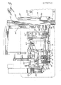
- the mechanism comprises a sewing guide member 11 which is securable to a foot arm 12 of the sewing machine.
- the sewing guide member 11 positions the elastic band 13 in a guided manner under the stitching needle 14 of the sewing machine.
- Guide means, in the form of a guide tunnel device 15, as well as tension guide jaws 16 guide the elastic band into the jaw opening 18 of the sewing guide member 11.
- the alignment of the elastic band 11 is adjusted by a transversely adjustable guide member 17.
- the elastic band 13 is advanced through the guide tunnel 15 by the feeddog 9 of the sewing machine and tension means 20-25 are provided to apply to the band.
- the band 13 is fed to the machine from a supply bin or roll (not shown) and fed through the tension guide jaws 16 to provide friction sliding fit with the elastic band to apply a slight tension thereto.
- the guide jaws 16 comprise a stationary plate 16 ⁇ and a spring bias plate 16 ⁇ having two coil springs 16′′′ bias there against to apply limited friction engagement with the band 13.
- the tension in the springs 16′′′ is adjustable.
- the band 13 then passes adjacent the adjustable guide member 17 whose position is adjustable by knob 17 ⁇ .
- the band 13 then passes through a pair of rolls which consist of a drive roll 20 which is connected to a drive shaft 21, and a drive idler roll 22 which is displaceably positionable toward the drive roll 20 to clamp the elastic band 13 therebetween.
- This drive roll 20 is driven at a speed inferior to the stitching speed of the sewing needle 14 and pulling speed of the feeddog 9 which pulls the elastic band to stretch the band which is held between the rolls 20-22.
- the drive idler roll 22, which is connected to the displacement support frame 23 is pulled away from the drive roll 20 by its piston 24, the drive roll is disengaged from the elastic band 13. This is done during the non-stretching cycle of the mechanism as will be described later.
- the drive means of the present invention is constituted by the feeddog 9, and the drive roll 20 which pulls the band from its supply bin or roll through the tension guide jaws 16 constitutes an adjustable stretching means.
- the stretching of the elastic band is controlled by the speed of rotation of the drive wheel 20 which will be described later.
- the tension means further includes a band stretching idler roll 25 which is also secured to a piston rod 26 and displaceable transversely to the long axis of the elastic band 13 to stretch the band in the area between the drive roll and the footplate guide.
- the length of the piston stroke or advancement of the piston rod 26 in the direction of arrow 27 is controlled by a pair of valves in a manner well known in the art. Accordingly, the amount of tension applied to the elastic band may be predetermined and adjusted.
- the guide idler roll 28 also constitutes a band storage roll which is displaceable to a retracted position as shown in Figure 4 to pull on the elastic band prior to being severed, such as shown at 30, whereby to pull a predetermined length of elastic band from the feed roll (not shown), and store same in an area between the tension guide jaws 16 and the guide tunnel 15.
- the elastic band 13 is then clamped in the jaws 16 by the piston head 37 (see Fig. 4) prior to being severed.
- the length of band 13 is stored in the longer travel path is sufficient to position a leading portion of the band under the sewing guide member 11, when lifted.
- the guide tunnel device 15 is provided with an adjustment screw 31 to adjust the dimension of the orifice through which the elastic band passes for maintaining the elastic band in planar alignment.
- the screws 31 ⁇ secure a moving wall (not shown) after the adjustment is made.
- a scissor element 32 constitutes a cutting means, and it is secured adjacent a lower flat surface 33 of the guide tunnel 15 and movable across a band exit orifice 34 whereby to sever the elastic band 13 at the exit orifice.
- a guide air nozzle 35 and intermediate nozzles 106 communicate with an air passage 105 and the tunnel 107, and constitutes a feed means of the elastic band through the guide tunnel 107 of the device 15 for directing the elastic leading portion in the direction of the jaw opening 18 of the sewing guide member 11, and as indicated by arrow 36, and under the member 11, which is lifted.
- the machine is now ready to start another stitching cycle.
- the jaw plate piston head 37 is retracted from jaw plate 16 ⁇ . Accordingly, a predetermined end portion 13 ⁇ of the elastic band 13 can be directed into the jaw opening 18 and under the sewing guide 11 to a precise position determined by the length of band pulled by the cylinder 28 ⁇ which also has an adjustable stroke.
- the sewing guide 11 comprises an attachment plate 40 having a screw bore 41 therein for attaching the plate to the foot arm 12 of the sewing machine.
- a single screw is all that is necessary to provide this attachment, and according the sewing guide 11 is easily attachable and removable from the foot arm 12 of the sewing machine when it is necessary not to utilize the feeding and tensioning mechanism of the present invention.
- a slot 42 is provided in the attachment plate 40 to accomodate the looper (not shown) of the sewing machine.
- a holding notch 43 is associated with the foot arm 12 where downward pressure is applied.
- the jaw opening 18 is provided with an adjustable guide block 44 which is adjustable laterally by the adjustment screw 45 whereby to accomodate elastic bands of different widths by varying the dimension of the guide passage 46 therein.
- the sewing guide 11 is further provided with a friction shoe 47 to apply a retention force on a trailing cut end portion 30 of the elastic band 13 which is still being sewn after the scissor element 32 has severed the elastic band.
- This friction plate is guided in a slot 48 and as a rounded friction end 49 for contact with the elastic band to frictionally retain the band against the guide wall 50 of the jaw opening 18.
- the friction plate 47 is spring-biased by means of a coil spring 51 disposed in a spring cavity 52 and resting against an abutment screw 53 whereby to bias the friction plate in a direction away from the guide wall 50.
- An air pressure hose 54 is connected to the top end of the friction shoe and displaces the show inwardly towards the guide wall 50 against the pressure of the spring 51 to apply a friction retaining force to the cut trailing end portion 30 of the elastic band to continue the stitching operation.
- the amount of retention force applied to the friction shoe 47 may be controlled by the air pressure to maintain a certain tension in the end portion of the elastic band proportional to the tension in the band portion already sewn.
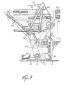
- the puller mechanism 60 comprises a rotatable friction engaging feed wheel 61 which is rotatably driven by a drive belt 64 supported between a drive wheel 63 and a driven wheel 62 in a displaceable linkage or frame 65.
- the shaft 62 ⁇ of the driven wheel 62 is connected to the feed wheel 61.
- the drive wheel 63 is connected to a drive shaft 63 ⁇ which, as shown in Figure 1, is connected to drive the main drive shaft 21 through a drive coupler 66 comprising a pair of coupling gears 67 and drive belt 68 disposed about a drive wheel 68 ⁇ and a driven wheel 68 ⁇ .
- This drive coupler has a ratio of 2:1 and ensures that the feed wheel 61 is driven at twice the speed as the main drive shaft 21.
- the fabric puller mechanism is utilized when a second elastic band 13 is applied to a fabric and its purpose is to provide a means to advance the fabric and to permit to stretch the already sewn elastic band and gathered fabric whereby the already stitched elastic band can be pulled back to its initial stretched position to have substantially uniform gathering across both elastic bands.
- the displacement linkage 65 is connected to a pressure applying cylinder 66 to apply downward pressure on the friction engaging drive wheel 61 which is positioned adjacent a cushion roll 61 ⁇ in the sewing surfaces whereby to apply retention pressure on the fabric 69 against the pulling force on the fabric exerted in the opposite direction to that of the feed by the operator, as above described.
- the displaceable linkage 65 is further connected to a retracting cylinder 67 and a lifting cylinder 68 to disengage the friction engaging feed element or wheel 61 from the fabric piece 69, and to position the puller mechanism 62 to a storage position.
- Figure 9 illustrates the puller mechanism in a retracted position during a stitching operation where it is not necessary to gather the material, such as at 70.
- Figure 10 illustrates the puller mechanism 65 in its storage position.
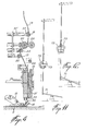
- FIG. 11 and 12 there is schematically illustrated the construction of a foot control pedal 71 which is associated with a pair of valves 72 and 73 to actuate selected ones of pistons whereby to effect the distribution or storage of the elastic and the reintroduction of the elastic band into the jaw opening of the footplate guide, as previously described and further to start the stitching needle.
- the interconnection of various valves to a pneumatic supply line whereby to actuate various pistons in sequence or to control the stroke thereof will not be described herein and becomes obvious after a person skilled in the art understands the construction operation of the apparatus decribed herein. Accordingly, such pneumatic control system with valve and piston connections will not be described.
- FIG. 13 and 14 there is shown a pivotal support frame 75 on which at least the guide tunnel device is secured whereby to displace the frame 75 to a storage position away from the stitching needle 14 whereby to utilize the sewing machine for ordinary use.
- the drive shaft 21 is uncoupled by simply disconnecting the spring-biased drive coupling element 74 (see Figure 1) which is in toothed engagement.
- the support frame 75 is also secured by eccentric connections 76 which also provide adjustable displacement of the guide tunnel device 15 in any direction for proper fine alignment thereof with the jaw opening 18 of the sewing guide member 11.
- the pivotal support frame is displaceable to a storage position, as shown in phantom lines at 77, and displaceable in the direction of arrow 78 to be clear from the sewing needle of the machine. This displacement can be done manually or by means of a piston (not shown).
- the scissor element 32 is activated by a cutter cylinder 79 which is connected to a linkage 80 which rotates a cutter shaft 81 to which is connected the scissor 32 through a torsion coil spring 82.
- a cutter cylinder 79 By rotating the shaft 81 torsion is applied to the spring which in turn causes the scissor element 32 to effect a fast displacement stroke against the orifice 34 in the lower face 33 of the guide tunnel device 15.
- the cutter cylinder 79 is operated through a push button valve (not shown) controlled by the operator.
- a speed control device 90 which consists essentially of two variable speed control adjusting elements 91 and 92.
- the device 92 is adjusted to control the speed of the drive tension roll 20, and as previously described this roll is driven slower than the feeddog speed whereby to stretch the elastic band. As shown in Figs. 1 and 8, this is accomplished by positioning a stopper pin 99 which is secured to a threaded block (not shown) displaceable on threaded rod 96.
- An indicator 96 ⁇ and grid 96 ⁇ provide for fine adjustment of the position of the pin 99.
- the pin 99 limits the forward stroke of the piston rod 98 of piston 97.
- the piston rod 98 is connected to a speed control arm 110 of a speed control box 100. The forward stroke reduces the speed of the drive 100 and then the low speed position of the arm 110 can be fixed for the desired low speed of the drive tension roll 20.
- the position of the pin 99 is adjusted by the knob 94 connected to the threaded shaft 96.
- the other control 91 is constructed similarly and its threaded shaft 95 has a displaceable block (not shown) and indicator 95 ⁇ connected to a pin 97 ⁇ to position the cylinder 97 at a desired position along an axis to vary the position of the speed control arm 110 in the retracted piston rod stroke which is the maximum speed desired by the speed control box 100.
- This maximum speed is adjusted to drive the puller wheel 61 at a desired speed depending on the speed of the sewing machine at the time of stitching the first elastic band to the garment.
- Figure 15 shows the position of the piston rod 98 extended for low speed drive of the tension drive roll 20 corresponding to the position of the mechanism of Fig. 3.
- Figure 16 shows the position of the piston rod 98 retracted for high speed drive, no tension being applied to the elastic band. This corresponds to the position of the mechanism as shown in Fig. 2.
- the elastic band 13 is fed through a pair of tention guide jaws 16 where a slight friction force is applied to maintain the elastic band taut against the pulling force of the feeddog 9.
- the apparatus is in the position as shown in Figure 2 with the idler pressure rod 22 retracted. Accordingly, the elastic band is sewn on the fabric piece 69 and the output of the stitching needle is, as shown in Figure 2, a flat fabric piece having a flat elastic band sewn thereon.
- the drive roll 20 When it is necessary to provide a gathered portion of the fabric, as shown in Figure 3 and as identified by reference numeral 70, the drive roll 20 is operated at a predetermined adjusted feed speed which is inferior to the pulling speed of the feeddog 9. Simultaneously the piston rod 26 to which is connected the elastic band stretching idler roll 25 is advanced in the direction of arrow 27 to further stretch the elastic band 13. The amount of stretching in the elastic band is controlled by the speed of rotation of the drive roll 20. After a predetermined amount of stretched elastic band has been sewn onto the fabric piece 69, the operator will effect a cutting stroke by pressing on the foot control pedal 71.
- the air supply to the nozzles 35 and 106 is actuated and the storage idler roll 28 is returned to its initial position, as shown in Figure 2, whereby the severed end portion 13 ⁇ of the elastic band is directed into the mouth opening 18 and under the sewing guide member 11 which has lifted.
- the air passage 105 is provided with intermediate orifices 106 which directs air into openings 107 adjacent the elastic band 13 in the tunnel 15 ⁇ whereby to push the elastic band downwardly sufficient to pull all the slack or stored portion of the elastic band below the tension guide jaws 16 which are closed.
- the guide member 11 moves down and the feeddog will advance the fabric piece 69 and the free end portion of the elastic 13 ⁇ thereunder for effecting a stitching operation.
- the piston head 37 is also retracted.
- the jet 35 merely guides the free end portion of the elastic band into the jaw plate.
- the puller mechanism 65 is then brought down to bear against the already sewn elastic band and effect its function as described in detail above.
Landscapes
- Engineering & Computer Science (AREA)
- Textile Engineering (AREA)
- Sewing Machines And Sewing (AREA)
Applications Claiming Priority (2)
| Application Number | Priority Date | Filing Date | Title |
|---|---|---|---|
| US15627 | 1987-02-17 | ||
| US07/015,627 US4703706A (en) | 1987-02-17 | 1987-02-17 | Elastic band feeding and tensioning mechanism for a sewing machine |
Publications (2)
| Publication Number | Publication Date |
|---|---|
| EP0279749A2 true EP0279749A2 (de) | 1988-08-24 |
| EP0279749A3 EP0279749A3 (de) | 1989-01-25 |
Family
ID=21772536
Family Applications (1)
| Application Number | Title | Priority Date | Filing Date |
|---|---|---|---|
| EP88400360A Withdrawn EP0279749A3 (de) | 1987-02-17 | 1988-02-17 | Zuführungs- und Spannvorrichtung von elastischem Band für eine Nähmaschine |
Country Status (3)
| Country | Link |
|---|---|
| US (1) | US4703706A (de) |
| EP (1) | EP0279749A3 (de) |
| BR (1) | BR8800628A (de) |
Cited By (2)
| Publication number | Priority date | Publication date | Assignee | Title |
|---|---|---|---|---|
| EP0476818A1 (de) * | 1990-08-03 | 1992-03-25 | Robert William Arthur Dagg | Verbesserung eines Verfahren und einer Vorrichtung zum Anbringen von elastischen Bändern an Kleidung |
| AT501023B1 (de) * | 1995-09-09 | 2007-11-15 | Schips Ag | Nähmaschine mit zuführeinrichtung |
Families Citing this family (25)
| Publication number | Priority date | Publication date | Assignee | Title |
|---|---|---|---|---|
| GB2201432B (en) * | 1987-02-26 | 1991-06-05 | Automatic Braiding Ltd | Feeding device for a sewing machine |
| FR2624141B1 (fr) * | 1987-12-08 | 1990-08-03 | Houot Bernard | Dispositif pour l'insertion automatique d'une bande elastique plate dans les coins d'un drap-housse |
| IT1221791B (it) * | 1988-05-30 | 1990-07-12 | Rockwell Rimoldi Spa | Macchina per cucire a base cilindrica |
| US4799441A (en) * | 1988-07-05 | 1989-01-24 | Boser Ronald J | Method of sewing elastic about a garment opening |
| DE3844043A1 (de) * | 1988-12-27 | 1990-07-05 | Cramer Anton Gmbh Co Kg | Bandzufuhreinrichtung fuer eine naehmaschine |
| US5269239A (en) * | 1990-09-10 | 1993-12-14 | Union Special Corporation | Automatic attachment of pre-closed elastic waistbands |
| US5394813A (en) * | 1993-10-12 | 1995-03-07 | Pegasus Sewing Machine Mfg. Co., Ltd. | Apparatus for sewing an elastic tape on an edge of a workpiece |
| ES2081754B1 (es) * | 1993-10-29 | 1998-07-16 | Betere Fab Lucia Antonio | Procedimiento para coser perimetralmente las aristas de conjuntos tapizados. |
| US5554968A (en) * | 1994-08-22 | 1996-09-10 | Lee; Raymond | Data communication using power lines |
| US6000352A (en) * | 1997-10-15 | 1999-12-14 | Porter Sewing Machines, Inc. | Method and apparatus for sewing fabric panels |
| US20030066593A1 (en) * | 2001-10-05 | 2003-04-10 | Alberto Kopelowicz | Elastic band |
| US6834603B1 (en) | 2002-03-05 | 2004-12-28 | Atlanta Attachment Company | Attachment gusset with ruffled corners and system for automated manufacture of same |
| US7100525B1 (en) | 2003-02-10 | 2006-09-05 | Atlanta Attachment Company, Inc. | System and method of finishing ruffled gussets/borders |
| US6968794B1 (en) | 2003-04-03 | 2005-11-29 | Atlanta Attachment Company | Presser foot control system |
| US6994043B1 (en) | 2003-05-20 | 2006-02-07 | Atlanta Attachment Company | Method of forming a mattress |
| US7543364B1 (en) | 2004-01-13 | 2009-06-09 | Atlanta Attachment Company | Border flanging and attachment gusset forming system |
| US7574788B1 (en) | 2004-10-01 | 2009-08-18 | Atlanta Attachment Company | Foundation cover stretching and stapling system |
| US7854022B2 (en) | 2005-01-10 | 2010-12-21 | Hbi Branded Apparel Enterprises, Llc | Garments having seamless edge bands and processes for making same |
| US7383780B1 (en) | 2005-04-18 | 2008-06-10 | Atlanta Attachment Company | Tape edge work station |
| US7950072B1 (en) | 2005-06-03 | 2011-05-31 | Violet Hanson | Reversible belt with slide buckle |
| US7984681B1 (en) | 2007-11-20 | 2011-07-26 | Atlanta Attachment Company | Automatic panel sewing and flanging system |
| CN102899816B (zh) * | 2011-07-26 | 2014-05-07 | 吕学忠 | 弹性带状料绷紧装置 |
| CN109576915A (zh) * | 2019-01-22 | 2019-04-05 | 利诚服装集团股份有限公司 | 一种用于制作吊带的缝纫机包缝辅助装置 |
| CN114000271B (zh) * | 2020-07-27 | 2023-03-21 | 杰克科技股份有限公司 | 一种主动供线装置、缝纫机以及主动供线方法 |
| FR3134121B1 (fr) * | 2022-03-29 | 2024-05-03 | Primo1D | Pied-de-biche reglable pour machine a coudre pour l’insertion d’une etiquette electronique dans une couture de confection |
Family Cites Families (14)
| Publication number | Priority date | Publication date | Assignee | Title |
|---|---|---|---|---|
| DE23750C (de) * | NÄHMASCHINENFABRIK JUNKER & RUH in Karlsruhe, Baden | Neuerungen an dem unter Nr. 21818 patentirten Apparat zum Aufnähen von Soutache für Nähmaschinen | ||
| US2821385A (en) * | 1952-10-01 | 1958-01-28 | Joseph M Hoffee | Belt making machine |
| US3792672A (en) * | 1971-06-29 | 1974-02-19 | Friedman F & Sons | Apparatus for cutting, folding and attaching tabs of flexible ribbon-like material |
| DE2448887A1 (de) * | 1974-10-14 | 1976-04-22 | Pfaff Ind Masch | Naehmaschine zum aufnaehen eines stoffstreifens auf einen stoffzuschnitt |
| US4024824A (en) * | 1975-09-05 | 1977-05-24 | Haff Jr Frederick | Sewing machine feeding and cutting attachment for elastic stripping |
| US4020776A (en) * | 1975-09-05 | 1977-05-03 | Haff Jr Frederick | Feeding and cutting attachment for sewing machines |
| IT1043088B (it) * | 1975-10-03 | 1980-02-20 | Rockwell Rimoldi Spa | Dispositivo per tagliare ed inse rire una striscia sotto il piedi no pressore di una macchina per cucire |
| US4132184A (en) * | 1977-05-23 | 1979-01-02 | Burton Perry E | Sheet material guidance system |
| US4182248A (en) * | 1977-08-08 | 1980-01-08 | Klages Arthur C | Fabric puller |
| US4147120A (en) * | 1977-09-14 | 1979-04-03 | Union Special Corporation | Auxiliary feed mechanism for sewing machines |
| US4438714A (en) * | 1981-11-27 | 1984-03-27 | Blue Grass Industries, Inc. | Radius blade cutting apparatus for a sewing machine |
| DE3425939A1 (de) * | 1983-12-30 | 1985-07-11 | Ram Elettronica di Badlagis Luca & C.S.n.c., Modena | Spannungseinsteller fuer elastikband und aehnliches, besonders fuer maschinen zum aufnaehen von band auf stoff |
| DE3410181C2 (de) * | 1984-03-20 | 1986-07-17 | Helmut Tübach Schips | Nähmaschine |
| DE8429919U1 (de) * | 1984-10-11 | 1985-05-30 | Bretz GmbH & Co KG, 6531 Gensingen | Pneumatisch gesteuerte Bandbremse für Kräuseleinrichtungen an Nähmaschinen (Industrienähmaschinen) |
-
1987
- 1987-02-17 US US07/015,627 patent/US4703706A/en not_active Expired - Fee Related
-
1988
- 1988-02-12 BR BR8800628A patent/BR8800628A/pt unknown
- 1988-02-17 EP EP88400360A patent/EP0279749A3/de not_active Withdrawn
Cited By (2)
| Publication number | Priority date | Publication date | Assignee | Title |
|---|---|---|---|---|
| EP0476818A1 (de) * | 1990-08-03 | 1992-03-25 | Robert William Arthur Dagg | Verbesserung eines Verfahren und einer Vorrichtung zum Anbringen von elastischen Bändern an Kleidung |
| AT501023B1 (de) * | 1995-09-09 | 2007-11-15 | Schips Ag | Nähmaschine mit zuführeinrichtung |
Also Published As
| Publication number | Publication date |
|---|---|
| US4703706A (en) | 1987-11-03 |
| BR8800628A (pt) | 1988-09-27 |
| EP0279749A3 (de) | 1989-01-25 |
Similar Documents
| Publication | Publication Date | Title |
|---|---|---|
| US4703706A (en) | Elastic band feeding and tensioning mechanism for a sewing machine | |
| US6196147B1 (en) | Folding and sewing apparatus | |
| DE3410181C2 (de) | Nähmaschine | |
| US4098201A (en) | Method and apparatus for hemming | |
| US5775191A (en) | Folding and sewing apparatus | |
| DE19535427A1 (de) | Nähmaschine und Verfahren zum automatischen Annähen eines Rippwarebands an den Leibteil eines Shirts | |
| US4024824A (en) | Sewing machine feeding and cutting attachment for elastic stripping | |
| US4674422A (en) | Apparatus for sewing zipper chain to elongated fabric pieces | |
| US4739718A (en) | Method and apparatus for sewing a waistband and applying it to a garment | |
| JPS6036314B2 (ja) | ミシンにおける縫糸を引き出しそして切断するための装置 | |
| US4030429A (en) | Sewing machine attachment | |
| US5345887A (en) | Thread manipulations at the beginning and end of a seam | |
| EP0476818A1 (de) | Verbesserung eines Verfahren und einer Vorrichtung zum Anbringen von elastischen Bändern an Kleidung | |
| US4173191A (en) | Sewing unit with sectionwise shiftable clamping device | |
| US2821385A (en) | Belt making machine | |
| US4561366A (en) | Apparatus for holding a cut segment of a selected length | |
| GB2058160A (en) | Apparatus for producing seam patterns of groups of stitches | |
| US4714038A (en) | Method for sewing zipper chain to elongated fabric pieces | |
| JP4022043B2 (ja) | 縫製縫い目によって作られる通路の張紐を開放することができるミシンおよび縫製方法 | |
| US3964410A (en) | Elastic inserter for a sewing machine | |
| US2665650A (en) | Scalloping device | |
| JPH01218491A (ja) | ミシンに使用される弾性バンド供給兼引張機構 | |
| US4366764A (en) | Apparatus for forming loops of strip material | |
| US3994246A (en) | Sewing apparatus | |
| US4376400A (en) | Improvements in a machine for applying a gusset to tubular articles such as women's pantyhose |
Legal Events
| Date | Code | Title | Description |
|---|---|---|---|
| PUAI | Public reference made under article 153(3) epc to a published international application that has entered the european phase |
Free format text: ORIGINAL CODE: 0009012 |
|
| AK | Designated contracting states |
Kind code of ref document: A2 Designated state(s): AT BE CH DE ES FR GB GR IT LI LU NL SE |
|
| PUAL | Search report despatched |
Free format text: ORIGINAL CODE: 0009013 |
|
| AK | Designated contracting states |
Kind code of ref document: A3 Designated state(s): AT BE CH DE ES FR GB GR IT LI LU NL SE |
|
| STAA | Information on the status of an ep patent application or granted ep patent |
Free format text: STATUS: THE APPLICATION IS DEEMED TO BE WITHDRAWN |
|
| 18D | Application deemed to be withdrawn |
Effective date: 19890922 |