EP0279864A1 - Anlage zur vorbeugung von katastrophen - Google Patents
Anlage zur vorbeugung von katastrophen Download PDFInfo
- Publication number
- EP0279864A1 EP0279864A1 EP87905787A EP87905787A EP0279864A1 EP 0279864 A1 EP0279864 A1 EP 0279864A1 EP 87905787 A EP87905787 A EP 87905787A EP 87905787 A EP87905787 A EP 87905787A EP 0279864 A1 EP0279864 A1 EP 0279864A1
- Authority
- EP
- European Patent Office
- Prior art keywords
- control
- fire
- terminal
- terminal units
- devices
- Prior art date
- Legal status (The legal status is an assumption and is not a legal conclusion. Google has not performed a legal analysis and makes no representation as to the accuracy of the status listed.)
- Granted
Links
Images


Classifications
-
- G—PHYSICS
- G08—SIGNALLING
- G08B—SIGNALLING SYSTEMS, e.g. PERSONAL CALLING SYSTEMS; ORDER TELEGRAPHS; ALARM SYSTEMS
- G08B26/00—Alarm systems in which substations are interrogated in succession by a central station
- G08B26/001—Alarm systems in which substations are interrogated in succession by a central station with individual interrogation of substations connected in parallel
Definitions
- the invention relates to a disaster protection system and more particularly, it relates to a protection system employing the polling method, wherein the workload of a fire control panel is reduced when controlling the terminal units, and which can easily be adapted to changes of the devices to be controlled.
- Some conventional fire protection systems employ the polling method which causes the fire control panel to circularly call the terminal units in order and to read from each of the called terminal units the state information (presence or absence of an abnormality signal from an abnormality sensor, or ON/OFF of the control circuits for devices to be controlled) or to control the called terminal units.
- the above terminal units may be slave units to which are connected abnormality sensors (fire detectors, gas sensors etc,) and/or devices to be controlled (fire doors, smoke control devices, smoke venting devices, fire extinguishing systems etc.), or those abnormality sensors or controlled devices themselves.
- abnormality sensors fire detectors, gas sensors etc,
- devices to be controlled fire doors, smoke control devices, smoke venting devices, fire extinguishing systems etc.
- the terminal units to be controlled and the time needed for the control are stored in advance in memory / means such as ROM's in the fire control panel so that the fire control panel may control the appropriate terminal units on the basis of the data stored in the memory means in case of an abnormality, such as a fire or a gas leak.
- the fire control panel sends a control start command to the terminal unit to be controlled and causes the control circuit in said terminal unit to operate. After the lapse of time required for control, the fire control panel sends a control termination command to the terminal unit to stop the operation of the control circuit. As to those terminal units requiring their reset after the extinguishment of the fire, the fire control panel sends a control start command and a control termination command at the time of the reset start and the reset termination, respectively.
- the present invention was made in view of these problems involved in conventional fire protection systems, and with the objective of creating a fire protection system such as a fire alarm system using the polling method which reduces the workload of the fire control panel when controlling the terminal units, and which may easily be adapted to changes of the devices to be controlled.
- the present invention was made in order to achieve said object. Namely, the present invention provides a disaster protection system for controlling terminal units themselves or devices to be controlled which are connected to said terminal units, according to a predetermined control command, through control circuits provided at the terminal units, wherein said terminal units have timer means which carry out a predetermined timing operation in response to the reception of said control command, whereby said terminal units themselves or said devices to be controlled are controlled during the time interval determined by the timimg operation.
- FIG 1 is a block diagram showing an embodiment of the present invention.
- a fire control panel 10 is connected with slave units C 1, C 2, C n. While devices other than the slave units C 1 - C n may also be connected as terminal units, the slave units alone are shown in Figure 1 as example.
- the fire control panel 10 is equipped with a CPU 11 for overall control, an operating part 12, an interface 13, a serial/parallel conversion circuit 14 converting serial data into parallel data (or vice versa), a signal transmission/receiving circuit 15 for signal transmission or receiving, an indication part 16 for indicating predetermined data, and an interface 17.
- the fire control panel 10 is also equipped with a ROM 1, a ROM 2, a ROM 3, a ROM 4, a ROM 5, a RAM 1, a RAM 2, a RAM 3, a RAM 4, and a RAM 5 which store the system program, the address classification map, the program for analyzing state information, the control program, the program for analyzing the control results, the polling address, the command codes, the terminal numbers and classifications of the terminal units to which the control state commands need to be sent, the terminal numbers and classifications of the terminal units ti which the reset commands need to be sent, the terminal numbers and classifications of the terminal units which need to be checked for proper control, respectively, and with a ROM 6 for working.
- FIG. 2 is a block diagram showing a practical example of the slave unit C 1.
- the slave units C 2 - C n too, have the same composition as that of slave unit C 1.
- the slave unit C 1 is equipped with a circuit 61 which detects the fire signal from a fire detector DE, with a control circuit 62 which controls an electric clock C of a fire door, a control timer TM 1 for the fire door control circuit 62, a control circuit 63 which controls the forward/reverse rotation of a motor M for a fire shutter, a timer TM 2 which controls the forward rotation time of the motor M, a timer TM 3 which controls the reverse rotation time of the motor M, a control circuit 64 which controls the forward/reverse rotation of a motor DM for a smoke venting damper, a timer TM 4 which controls the forward rotation of the motor DM, and a timer TM 5 which controls the reverse rotation of the motor DM.
- the timers TM 1 - TM 5 have their operating times set for the intended controls, for example, TM 1 has an operating time of 5 seconds, TM 2 of 60 seconds, TM 3 of 90 seconds, and both TM 4 and TM 5 have 20 seconds.
- the fire door control circuit 62, the fire shutter control circuit 63, and the smoke venting damper control circuit 64 are shown as examples of control circuits which control the terminal units themselves or devices connected with and controlled by the terminal units.
- the fire door, the fire shutter, and the smoke venting damper are shown as examples of controlled devices.
- the timers TM 1 - TM 5 are shown as examples of the timer means which are triggered by the control command signal from the fire control panel and generate an output for a predetermined length of time.
- the output time of the timer means is adjustable.
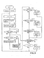
- FIG. 3 is a flowchart showing the operation of the fire control panel 10.
- a terminal number n (a ter- m inal unit number, i.e. a polling address) is incremented by 1 (S 2) and referred to the terminal numbers and classifications stored in the RAM 3 - RAM 5, with respect to the terminal units to which the control start command, the reset command, and the command for checking the controls need to be sent. If there is the terminal number n in one of the RAM 3 - RAM 5, a corresponding command code is prepared. In the absence of the terminal number n in any of them, a command code requesting a state information is prepared (S 3). Then, the address code and the command code prepared in step S 3 are sent to the terminal unit (S 4).
- the state information is analyzed by the analyzing program stored in ROM 3 and indicated by indicator 16 (s 8).
- the classification (classification of the control device) and the number n of the terminal unit are stored in the RAM 3 (S 12). If it is necessary to reset the controlled device (S 13), the classification and the terminal number n of the controlled device are stored in the RAM 4 (S 14). If it is required to know a result of the control (S,15), the classification and the terminal number n of the device to which the command for checking the control applies is stored in the RAM 5 (S 16).
- FIG. 4 is a flowchart showing the operation of the slave unit C 1.
- the initial value is set (S 31). If there is a return signal through the signal line (S 32), and yet the polling terminal number (address) in the return signal matches the terminal number stored in ROM 2 (S 33), the state information is stored (S 34).
- the state information includes data indicating whether or not there is a fire signal from the fire signal detecting circuit 61 and the ON/OFF state of each of the control circuit 62, 63, 64 for the fire door, the fire shutter, and for thesmoke venting damper, respectively.
- the command code in the return signal received from the fire control panel 10 is decoded. If this command code is a control command (S 35) and yet a control start command (S 41), the timers TM 1, TM 2, TM 4 are triggered (S 42) to send the state information of the detecting circuit 61 and the control circuits 62 - 64 which had previously been read and stored at step S 34 to the fire control panel 10 (S 43). With the outputs of the timers TM 1, TM 2, TM 4 the control circuits 62 - 64 are operated for a predetermined time to close the fire door and the fire shutter, and to open the smoke venting damper, resp.
- the control command is a reset command (S 51)
- the timers TM 3, TM 5 are triggered (S 52) to send the state information which has already been read and stored at step S 34 to the fire control panel 10 (S 43).
- the control circuits 63, 64 are operated for the predetermined time to open the fire shutter and to close the smoke venting damper, respectively.
- the control results of the controlled devices (Information as to open/ close of the fire door, the fire shutter, and the smoke venting damper) are read from the respective control circuits (S 62), and the information on the control results and the state information stored at step S 34 are sent to the fire control panel 10 (S 63).
- information on results of the controls is given with respect to those controlled devices which need to be checked for their proper controls, while state information of the control circuits is given with respect to those controlled devices which need not to be checked for their controls. Then, the operation of the slave unit terurns to step S 32.
- each of the control circuits in the terminal units is provided with a control timer which is triggered by the command from the fire control panel and generates an output signal to. the control circuit in the terminal unit for a predetermined length of time (Time needed for control).
- a control timer which is triggered by the command from the fire control panel and generates an output signal to. the control circuit in the terminal unit for a predetermined length of time (Time needed for control).
- control timers which control the operating time of the control circuits, it is possible to perform precise control of the control devices and to control each terminal unit within the optimum length of time, and consequently the power consumption for control can be reduced.
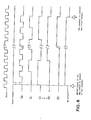
- Figure 5 shows an example of the timers TM 1 - TM 5, the output time of which can optionally be changed by means of the dip switches, thus they can be adapted to devices of the same kind which have different control times (timer output times).
- Figure 6 is a time chart showing the operation of the timers shown in Figure 5. This time chart shows a case where an 8-bit binary counter with preset priority function is used.
- the time T of the timer output (optput of the OR circuit) is given by the following formula:
- the length of the output time of the timer is variable within a range of 1 second - 255 seconds.
- the numerical value indicated on the counter at the time of turning on the power supply is set to zero by the power-on reset signal immediately after the power-on, and the output of the OR circuit reaches the L level, causing the counter to clear itself through the AND circuit and to lock in the cleared state.
- the counter is released from the cleared state when the start pulse is applied, and the ON/OFF state of the dip switches S 0 - S 7 is preset in the counter. After this, the counter keeps counting and again returns to and locks in the cleared state when overflowed (the output of all of Q 0 - Q 7 reached the H level). Thus, the output of the OR circuit remains at the H level for the above T seconds, and consequently the counter circuit fulfills the function of the timer.
- the start pulse is generated by the terminal unit CPU 50 upon receipt of the reset command from the fire control panel and sent to the timer through I/F.
- the present invention has such effects that the workload of the fire control panel when controlling the terminal units in a fire protection system using the polling method is reduced, and the work required for changes of devices to be controlled is readily performed.
Landscapes
- Business, Economics & Management (AREA)
- Emergency Management (AREA)
- Physics & Mathematics (AREA)
- General Physics & Mathematics (AREA)
- Alarm Systems (AREA)
- Fire Alarms (AREA)
- Fire-Extinguishing By Fire Departments, And Fire-Extinguishing Equipment And Control Thereof (AREA)
Applications Claiming Priority (2)
| Application Number | Priority Date | Filing Date | Title |
|---|---|---|---|
| JP210469/86 | 1986-09-05 | ||
| JP61210469A JPH0783775B2 (ja) | 1986-09-05 | 1986-09-05 | 防災設備 |
Publications (3)
| Publication Number | Publication Date |
|---|---|
| EP0279864A1 true EP0279864A1 (de) | 1988-08-31 |
| EP0279864A4 EP0279864A4 (de) | 1989-09-11 |
| EP0279864B1 EP0279864B1 (de) | 1992-07-08 |
Family
ID=16589852
Family Applications (1)
| Application Number | Title | Priority Date | Filing Date |
|---|---|---|---|
| EP87905787A Expired - Lifetime EP0279864B1 (de) | 1986-09-05 | 1987-09-02 | Anlage zur vorbeugung von katastrophen |
Country Status (4)
| Country | Link |
|---|---|
| EP (1) | EP0279864B1 (de) |
| JP (1) | JPH0783775B2 (de) |
| DE (1) | DE3780294T2 (de) |
| WO (1) | WO1988001521A1 (de) |
Cited By (5)
| Publication number | Priority date | Publication date | Assignee | Title |
|---|---|---|---|---|
| EP0587898A4 (de) * | 1992-02-04 | 1994-11-30 | Nohmi Bosai Ltd | Feueralarm. |
| EP0587899A4 (de) * | 1992-02-04 | 1994-11-30 | Nohmi Bosai Ltd | Feueralarm. |
| EP0651363A1 (de) * | 1993-10-26 | 1995-05-03 | Nohmi Bosai Ltd. | Alarmsystem zur Überwachung eines Feuers |
| CN103191539A (zh) * | 2013-03-07 | 2013-07-10 | 上海松江飞繁电子有限公司 | 一种有关消防联动设备的多线控制装置及方法 |
| EP3010000A1 (de) | 2014-10-17 | 2016-04-20 | Siemens Schweiz AG | Steuersystem von betätigten Sicherheitsvorrichtungen |
Families Citing this family (2)
| Publication number | Priority date | Publication date | Assignee | Title |
|---|---|---|---|---|
| US5350019A (en) * | 1986-09-05 | 1994-09-27 | Nohmi Bosai Kogyo Kabushiki Kaisha | Fire protection system |
| RU2128536C1 (ru) * | 1997-01-22 | 1999-04-10 | Горбань Юрий Иванович | Роботизированная установка пожаротушения |
Family Cites Families (5)
| Publication number | Priority date | Publication date | Assignee | Title |
|---|---|---|---|---|
| DE2533354C3 (de) * | 1975-07-25 | 1979-08-30 | Siemens Ag, 1000 Berlin Und 8000 Muenchen | Einrichtung zum Übertragen von Steuerbefehlen in einem Brandschutzsystem |
| JPS6138600Y2 (de) * | 1979-01-27 | 1986-11-07 | ||
| JPS5683895U (de) * | 1979-12-01 | 1981-07-06 | ||
| JPS6092383U (ja) * | 1983-11-30 | 1985-06-24 | セコム株式会社 | 集中遠隔監視システム |
| JPH06116396A (ja) * | 1992-10-02 | 1994-04-26 | Kanebo Ltd | 繊維とフェノール系樹脂とからなる複合構造体の製造方法 |
-
1986
- 1986-09-05 JP JP61210469A patent/JPH0783775B2/ja not_active Expired - Fee Related
-
1987
- 1987-09-02 DE DE19873780294 patent/DE3780294T2/de not_active Expired - Lifetime
- 1987-09-02 WO PCT/JP1987/000654 patent/WO1988001521A1/ja not_active Ceased
- 1987-09-02 EP EP87905787A patent/EP0279864B1/de not_active Expired - Lifetime
Cited By (8)
| Publication number | Priority date | Publication date | Assignee | Title |
|---|---|---|---|---|
| EP0587898A4 (de) * | 1992-02-04 | 1994-11-30 | Nohmi Bosai Ltd | Feueralarm. |
| EP0587899A4 (de) * | 1992-02-04 | 1994-11-30 | Nohmi Bosai Ltd | Feueralarm. |
| US5461370A (en) * | 1992-02-04 | 1995-10-24 | Nohmi Bosai, Ltd. | Fire alarm system |
| US5493271A (en) * | 1992-02-04 | 1996-02-20 | Nohmi Bosai Ltd. | Fire alarm system |
| EP0651363A1 (de) * | 1993-10-26 | 1995-05-03 | Nohmi Bosai Ltd. | Alarmsystem zur Überwachung eines Feuers |
| CN103191539A (zh) * | 2013-03-07 | 2013-07-10 | 上海松江飞繁电子有限公司 | 一种有关消防联动设备的多线控制装置及方法 |
| CN103191539B (zh) * | 2013-03-07 | 2015-06-17 | 上海松江飞繁电子有限公司 | 一种有关消防联动设备的多线控制装置及方法 |
| EP3010000A1 (de) | 2014-10-17 | 2016-04-20 | Siemens Schweiz AG | Steuersystem von betätigten Sicherheitsvorrichtungen |
Also Published As
| Publication number | Publication date |
|---|---|
| EP0279864B1 (de) | 1992-07-08 |
| DE3780294D1 (de) | 1992-08-13 |
| JPH0783775B2 (ja) | 1995-09-13 |
| WO1988001521A1 (fr) | 1988-03-10 |
| JPS6365879A (ja) | 1988-03-24 |
| EP0279864A4 (de) | 1989-09-11 |
| DE3780294T2 (de) | 1992-12-17 |
Similar Documents
| Publication | Publication Date | Title |
|---|---|---|
| US4755792A (en) | Security control system | |
| US7472106B2 (en) | Safety network system and safety slave | |
| CA1333942C (en) | Data setting system for terminal units in remote supervisory and controlling system employing multiplex data transmission | |
| CN110959273B (zh) | 用于房屋自动化的设备 | |
| US4339746A (en) | Alarm control center | |
| WO1993022755A1 (en) | Surveillance and alarm device for room spaces | |
| EP0279864A1 (de) | Anlage zur vorbeugung von katastrophen | |
| EP0206483A2 (de) | Sicherheitssteuerungssystem | |
| US5699430A (en) | Method and apparatus for electronically preventing unauthorized access to equipment | |
| US5350019A (en) | Fire protection system | |
| EP0162280B1 (de) | Bremseinrichtung für eine automatische Tür | |
| US3952285A (en) | Security polling transponder system | |
| US4805519A (en) | Control system | |
| EP0084685B1 (de) | Alarm-Steuer-Zentrum | |
| US3840871A (en) | Control system for an alarm installation having a remote transmitter with a remotely controlled emergency device | |
| KR200268301Y1 (ko) | 도어의 개폐 제어장치 | |
| JP3337872B2 (ja) | 物体検知装置 | |
| EP0281633B1 (de) | Signalsenderanordnung eines unglückverhinderungssystems | |
| JPH0452897A (ja) | 火災受信機 | |
| KR970068243A (ko) | 무인기지국 자동제어장치를 부가한 무인기지국(rt) 및 그 제어방법 | |
| JPS62145940A (ja) | 流体制御弁通信システム | |
| JP3087124B2 (ja) | 火災判別方法およびこの方法を実施するための火災受信機、中継器、自火報システム | |
| RU194227U1 (ru) | Повторитель интерфейсов для прибора приемно-контрольного и управления пожарного адресно-аналогового | |
| SU773632A1 (ru) | Устройство дл централизованного непрерывного контрол параметров | |
| SU1695344A1 (ru) | Устройство дл контрол и учета работы оборудовани |
Legal Events
| Date | Code | Title | Description |
|---|---|---|---|
| PUAI | Public reference made under article 153(3) epc to a published international application that has entered the european phase |
Free format text: ORIGINAL CODE: 0009012 |
|
| 17P | Request for examination filed |
Effective date: 19880425 |
|
| AK | Designated contracting states |
Kind code of ref document: A1 Designated state(s): CH DE FR GB LI SE |
|
| A4 | Supplementary search report drawn up and despatched |
Effective date: 19890911 |
|
| 17Q | First examination report despatched |
Effective date: 19910304 |
|
| RAP1 | Party data changed (applicant data changed or rights of an application transferred) |
Owner name: NOHMI BOSAI LTD. |
|
| GRAA | (expected) grant |
Free format text: ORIGINAL CODE: 0009210 |
|
| AK | Designated contracting states |
Kind code of ref document: B1 Designated state(s): CH DE FR GB LI SE |
|
| REF | Corresponds to: |
Ref document number: 3780294 Country of ref document: DE Date of ref document: 19920813 |
|
| ET | Fr: translation filed | ||
| PLBE | No opposition filed within time limit |
Free format text: ORIGINAL CODE: 0009261 |
|
| STAA | Information on the status of an ep patent application or granted ep patent |
Free format text: STATUS: NO OPPOSITION FILED WITHIN TIME LIMIT |
|
| 26N | No opposition filed | ||
| EAL | Se: european patent in force in sweden |
Ref document number: 87905787.5 |
|
| PGFP | Annual fee paid to national office [announced via postgrant information from national office to epo] |
Ref country code: FR Payment date: 19990807 Year of fee payment: 13 |
|
| PGFP | Annual fee paid to national office [announced via postgrant information from national office to epo] |
Ref country code: CH Payment date: 19990813 Year of fee payment: 13 |
|
| PGFP | Annual fee paid to national office [announced via postgrant information from national office to epo] |
Ref country code: SE Payment date: 19990816 Year of fee payment: 13 |
|
| PGFP | Annual fee paid to national office [announced via postgrant information from national office to epo] |
Ref country code: GB Payment date: 19990818 Year of fee payment: 13 |
|
| PGFP | Annual fee paid to national office [announced via postgrant information from national office to epo] |
Ref country code: DE Payment date: 19990825 Year of fee payment: 13 |
|
| PG25 | Lapsed in a contracting state [announced via postgrant information from national office to epo] |
Ref country code: GB Free format text: LAPSE BECAUSE OF NON-PAYMENT OF DUE FEES Effective date: 20000902 |
|
| PG25 | Lapsed in a contracting state [announced via postgrant information from national office to epo] |
Ref country code: SE Free format text: THE PATENT HAS BEEN ANNULLED BY A DECISION OF A NATIONAL AUTHORITY Effective date: 20000929 |
|
| PG25 | Lapsed in a contracting state [announced via postgrant information from national office to epo] |
Ref country code: LI Free format text: LAPSE BECAUSE OF NON-PAYMENT OF DUE FEES Effective date: 20000930 Ref country code: CH Free format text: LAPSE BECAUSE OF NON-PAYMENT OF DUE FEES Effective date: 20000930 |
|
| GBPC | Gb: european patent ceased through non-payment of renewal fee |
Effective date: 20000902 |
|
| REG | Reference to a national code |
Ref country code: CH Ref legal event code: PL |
|
| EUG | Se: european patent has lapsed |
Ref document number: 87905787.5 |
|
| PG25 | Lapsed in a contracting state [announced via postgrant information from national office to epo] |
Ref country code: FR Free format text: LAPSE BECAUSE OF NON-PAYMENT OF DUE FEES Effective date: 20010531 |
|
| REG | Reference to a national code |
Ref country code: FR Ref legal event code: ST |
|
| PG25 | Lapsed in a contracting state [announced via postgrant information from national office to epo] |
Ref country code: DE Free format text: LAPSE BECAUSE OF NON-PAYMENT OF DUE FEES Effective date: 20010703 |