EP0279910A2 - Pompe avec montage modulaire - Google Patents
Pompe avec montage modulaire Download PDFInfo
- Publication number
- EP0279910A2 EP0279910A2 EP87116030A EP87116030A EP0279910A2 EP 0279910 A2 EP0279910 A2 EP 0279910A2 EP 87116030 A EP87116030 A EP 87116030A EP 87116030 A EP87116030 A EP 87116030A EP 0279910 A2 EP0279910 A2 EP 0279910A2
- Authority
- EP
- European Patent Office
- Prior art keywords
- pump
- housing
- drive unit
- inlet
- outlet
- Prior art date
- Legal status (The legal status is an assumption and is not a legal conclusion. Google has not performed a legal analysis and makes no representation as to the accuracy of the status listed.)
- Ceased
Links
Images


Classifications
-
- F—MECHANICAL ENGINEERING; LIGHTING; HEATING; WEAPONS; BLASTING
- F04—POSITIVE - DISPLACEMENT MACHINES FOR LIQUIDS; PUMPS FOR LIQUIDS OR ELASTIC FLUIDS
- F04B—POSITIVE-DISPLACEMENT MACHINES FOR LIQUIDS; PUMPS
- F04B53/00—Component parts, details or accessories not provided for in, or of interest apart from, groups F04B1/00 - F04B23/00 or F04B39/00 - F04B47/00
Definitions
- the invention relates to a pump according to the preamble of claim 1.
- the known pump which is intended and suitable for a low pressure, is a unit which is independent of the driving motor, often an electric motor, and which is only connected to the electric motor or the motor housing via a flange connection.
- the pump is modular in a very convenient, namely very simple, light and inexpensive way.
- the cohesion of all parts of the pump is ensured by a support designed as a U-shaped frame, which is flanged to the motor end shield with its plate-like web.
- the two pump units are arranged mirror-symmetrically to one another on the plate-like U-legs of the carrier.
- the housings of the pump units are relatively jagged and on the one hand have a tubular part with inlet and outlet and for receiving a suction valve or a pressure valve, on the other hand a cylindrical part protruding from the tubular part at right angles as a working space and for guiding a pump piston.
- Valve body of the suction valve and pressure valve can be inserted into the end openings of the housing and the end openings can then be closed with end caps. All parts are fully braced by attaching the pump units to the carrier.
- the bushings for the piston rods or the pump pistons forming the piston rods on the two housings of the pump units are arranged on the long sides of the housings and are aligned with one another.
- the pump pistons are combined with a U-shaped power transmission element.
- a cam roller engages in the power transmission element as the drive element of the drive unit.
- the cam roller sits with its axis of rotation eccentrically to the longitudinal axis of the drive shaft on the end face. Possibly.
- a suitable permanent lubrication can be provided here. This open construction naturally results in good cooling, particularly in the area of the drive unit with drive element and power transmission element.
- the known pump is particularly expedient insofar as the carrier has an opening for the passage of the drive shaft in association with the power transmission element of the drive unit. Since the carrier with the plate-shaped U-web can be flanged directly to the end shield of the motor, the output-side bearing of the output shaft, namely the output-side armature bearing of the electric motor, can be used, for example, when using an electric motor as the bearing of the input shaft.
- the two pump units are attached to the U-legs of the carrier from the outside thereof, the part of the housing which projects vertically and which forms the working space is inserted through a correspondingly shaped opening in the U-leg. Threaded rods protrude laterally from the carrier, onto which the housings can be pushed using push-through holes.
- a flange-like edge surrounding the opening for the passage of the part of the housing which has the working space cooperates with an annular flange on the housing of each pump unit itself in such a way that the pump units are simultaneously aligned and adjusted to one another by tensioning the pump units.
- High-pressure pumps known from practice i.e. pumps for a pressure range from 20 bar to 100 bar, in particular a pressure range from 40 bar to 80 bar, are primarily so expensive because one does not have to do without a large and heavy, all-encompassing metal housing believes to be able to.
- This housing is usually flanged to the engine block of a drive motor via another support structure.
- a drive shaft of the high-pressure pump which is mounted twice in the housing itself, is connected via a flange connection located between the housing of the drive motor and the housing of the high-pressure pump.
- the invention is based on the object of designing the known pump with a modular structure with low material and cost expenditure so that it is suitable as an inexpensive product for use at high pressures above 20 bar.
- the object outlined above is achieved by the features of the characterizing part of claim 1.
- the modular structure of the pump remains.
- the skilful arrangement of the inlets and outlets on the housings of the pump units ensures, however, that all lines can be routed extremely short and optimally straight.
- the considerable forces occurring at the inlets and outlets of the two pump units due to the pumping at high pressure are exactly opposed to one another with regard to the force effect, so that they compensate for one another and are in any case optimally interceptable on the carrier.
- the housings of the pump units automatically form the optimal abutments for these forces.
- the modular pump for the high pressure range explained above can also work with only one pump unit, but for reasons of dynamic and static optimization, two pump units will usually be selected symmetrically to one another, as is always done in the prior art.
- the pressure and suction valves it is advisable to fully integrate them into the housing, in other words to implement removable screw inserts, as are known as such for high-pressure pumps.
- the drive unit 2 is via a drive element 4, which is shown in dashed lines in FIG. 5 and here has the shape of an eccentric cam, and a power transmission element 4 which engages with the drive element 4, which can also be seen in FIG. 5 and is designed here as an eccentric cage a drive shaft 7 driven by a motor, here and in particular an electric motor 6, can be coupled.
- the drive shaft 7 is also shown in dashed lines in FIG. 5.
- the drive unit 2 can convert a rotary movement of the drive shaft 7 into a displacement movement.
- the drive unit 2 can also be designed so that the drive movement coming from the motor is already a displacement movement, so that a conversion within the drive unit 2 is no longer necessary.
- each puncturing unit 3 has a working space with a suction valve arranged at an inlet 8 and a pressure valve arranged at an outlet 9. Furthermore, each pump unit 3 has a pump piston which is guided in a pressure-tight manner in the work space and can be moved back and forth for pumping in the work space. The pump pistons can be driven by the drive unit 2.
- each pump unit 3 has its own elongated block-like or cylindrical housing 10 with the working space, the inlet 8, the suction valve arranged at the inlet 8, which is integrated here in the housing 10, the outlet 9, the pressure valve arranged at the outlet 9, which is also integrated here in the housing 10, the pump piston and a pressure-tight bushing 11 arranged on a longitudinal side of the housing 10 for a piston rod 12 connected to the pump piston or forming the pump piston.
- the drive unit 2 is designed without a housing, that is to say it consists only of the piston rods 12, the force transmission element 5 and the drive element 4.
- the inlet 8 and the outlet 9 are also arranged at the end and the longitudinal axes of the inlet 8 and the outlet 9 are aligned parallel to the longitudinal axis of the bushing 11 and that the housings 10 are arranged on the support 13 with the longitudinal sides having the bushing 11, the inlet 8 and the outlet 9 facing one another. 5 shows this very clearly in connection with FIG. 1. It also applies here that the bushings 11, the inlets 8 and the outlets 9 are aligned with one another.
- the inlets 8 and outlets 9 of the housings 10 of the pump units 3 are each connected to one another and to a central inlet 21 and a central outlet 22 via a manifold 20 .
- the manifolds 20 are straight pipe sections and the central inlet 21 or central outlet 22 are designed as T-pieces.
- the inlets 8 and outlets 9 of the housing 10 are designed as pressure-tight sockets for the ends of the manifolds 20 designed as straight line pieces.
- the inlets 8 and outlets 9 configured as sliding seats for the manifolds 20 allow the distance between the To change pump units 3 over a relatively large range without changing the relative angular position of the pump units 3.
- the manifolds 20 in the sockets of the inlets 8 and outlets 9 serve for angular adjustment of the housing 10 of the pump units 3.
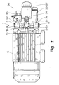
- FIG. 1 makes it clear in connection with FIG. 2 that the longitudinal axes of the central inlet 21 and the central outlet 22 are aligned parallel to one another.
- Fig. 5 it can be seen that there may also be a further connection 25 for either a separate connection line or a pulsation damper.
- the housing 10 of each pump unit 3 has an opening 24 closed by a threaded plug 23 on the side of the working space facing away from the bushing 11 of the piston rod 12.
- the housing 10 of the pump units 3 must be firmly connected to the carrier 13. This fixed connection is ensured in the illustrated embodiment by screw fastenings to be explained in more detail later. It is not shown in the drawings that the housing of the pump units on the carrier can be formed in one piece and the carrier u. U. can form a one-piece casting or pressed part with the housings. Brass, aluminum, and possibly also modern plastics, for example polyacetal, can be used as the material.
- the carrier 13 is U-shaped. This is expensive, especially with regard to the material consumption. According to an independent and independent teaching of the invention, the carrier 13 is now in the pump 1 shown here Solid-plate-shaped, it represents a solid support plate. This has the advantages explained above and solves the task in an independent way.
- the design of the carrier 13 as a solid support plate has the further advantage that, as shown here, the carrier 13 can be formed by the correspondingly designed bearing plate of the motor 6 designed as an electric motor. This is of course extremely cost-saving, since the anyway existing, anyway very solidly designed bearing plate now also serves as a solid backbone for the arrangement of the individual parts of pump 1. This completely saves the weight and cost of a separate carrier 13.
- the carrier 13 has an opening 14 for the passage of the drive shaft 7 in association with the force transmission element 5 of the drive unit 2.
- a special bearing for mounting the drive shaft 7 in the carrier 13 designed as a support plate is not required here in a particularly expedient manner because the carrier 13 here is the end shield of the electric motor 6 is.
- the bearing of the drive shaft 7 is thus actually the armature bearing of the electric motor 6 on the output side.
- the pump 1 itself no longer needs a bearing for its drive shaft 7.
- the armature bearings of the electric motor 6 are therefore used in two ways, on the one hand as an armature bearing of the output shaft of the electric motor 6 , on the other hand, functionally, as a rotary bearing of the drive shaft of the pump 1.
- FIG. 3 to 5 show how the housing 10 can be connected to the carrier 13.
- Welded connections, soldered connections, clamped connections, snap-in connections, etc. could be provided here, but specifically, as in the prior art, screw fastenings 15 are implemented.
- These screw fastenings 15 could comprise threaded shafts as in the prior art, but in the exemplary embodiment shown it applies that the support 13 has a plurality of threaded connections, in particular two threaded connections per pump unit 3 Has screw fasteners 15 into which fastening screws 16 can be screwed.
- the housings 10 of the pump units 3 have corresponding through bores 17 for the fastening screws 16.
- the screw fastenings 15 designed as threaded connections and the push-through bores 17 have centering surfaces 18 which correspond to one another. These centering surfaces 18 are expediently slightly conical in order to facilitate attachment of the pump 1 to the carrier 13.
- the design of the threaded connector allows particularly practical integration into a support 13 designed as a solid support plate.
- the carrier 13, here in the form of the end shield of the electric motor 6, serves as the backbone of the pump 1, so to speak.
- the mutual exact position of the various functional assemblies of the pump 1 is thus ensured by the carrier 13. Consequently, the functional assemblies, in particular the pump units 3, must be able to be brought into a very exact relative position to the carrier 13.
- the adjustment surfaces 19 which can be seen in FIGS. 2 and 3 are used for this purpose, which are dimensioned very precisely and are designed to be largely wear-resistant.
- the housing 10 can be clamped against these adjustment surfaces 19 with the aid of the fastening screws 16.
- the pump 1 in the exemplary embodiment shown is constructed in such a way that the adjusting surfaces 19 seen from the drive unit 2 are beyond the screw fastenings 15, preferably as far as possible beyond are arranged.
- the force transmission element is also essentially U-shaped with laterally projecting piston rods 12. This can be seen particularly clearly in FIG. 5.
- the drive element 4 is a cam roller.
- Such cam rollers are commercially available and ultimately represent nothing more than a cylinder-jacket-shaped outer ring made of highly wear-resistant material, which can be rotated with respect to a concentrically arranged inner ring via a sealed ball bearing or roller bearing. A permanent fat filling is usually provided at the same time.
- the inner ring can be fixed at any point.
- This construction of the drive element 4 corresponds in a particularly expedient manner to the construction of the force transmission element 5 with an essentially U-shaped cross section.
- Fig. 5 shows with the broken line of the drive element 4 and the drive shaft 7 that a particularly simple and expedient attachment of the drive element 4 to the drive shaft 7 has been realized, which is particularly suitable for the case that the drive shaft 7 is formed by the output shaft of the electric motor 6. It is namely the case here that the cam roller forming the drive element 4 is mounted with its axis of rotation offset eccentrically to the longitudinal axis of the drive shaft 7 on the end face of the drive shaft 7.
- the overall open construction corresponds to the fact that the power transmission surfaces of the drive element 4 and the power transmission element 5 coming into contact with one another consist of wear-resistant and / or self-lubricating, in particular graphite-containing material.
- Fig. 2 shows that the pump 1 is followed by a bypass device 26, as is known as such from the prior art.
- the bypass device 26 is hydraulically connected between the central outlet 22 and the central inlet 21 and has a pressure relief valve 27 connected downstream of the central outlet 22 and a return line 28 leading from the pressure relief valve 27 to the central inlet 21.
- 6 shows the bypass device 26 in somewhat more detail. It follows from this that the bypass device 26 is also designed as an open construction, that is to say with an exposed pressure relief valve 27, an exposed return line 28, connecting lines 29, etc. It applies that the bypass device 26 consists essentially of plastic, in particular polyacetal, and is preferably designed as an injection molded part.
- Fig. 6 shows that individual parts can be designed as screw inserts made of metal, as is known per se in comparable constructions. 6 shows that the individual parts of the bypass device 26 are connected and stiffened via stiffening webs 30.
- FIG. 1 shows in connection with Fig. 5 that in the embodiment shown here, the central inlet 21 has an elongated connector 31.
- This elongated connecting piece 31 can now be used in connection with a corresponding design of the central outlet 22 for fastening the bypass device 26 to the pump 1.
- the elongated connection piece 31 has a lateral bore 32, so that liquid can enter the connection piece 31 from the outside.
- the bypass device 26 has, as shown particularly clearly in FIG. 1, an elongated sleeve 33.
- the return line 28 from the pressure relief valve 27 opens into the sleeve 33. If the sleeve 33 is now pushed over the connecting piece 31 when the bypass device 26 is attached, this can be done in such a way that the bore 32 is aligned with the mouth of the return line 28 into the sleeve 33 .
- the bypass device 26 shown in detail in FIG. 6 also has a manometer 34 assigned to the pressure relief valve 27.
- the pressure relief valve 27 as such is designed in a manner known per se as a piston valve with two piston surfaces of different sizes.
- the central outlet 22 is followed by an injection unit 35, which operates in the manner of a water jet pump and allows chemicals to be injected or sucked into the pumped liquid.
- housings 10, manifolds 20, etc. consist of, optionally cast or pressed, brass, aluminum or the like, or of plastic, in particular of polyacetal.
Landscapes
- Engineering & Computer Science (AREA)
- Mechanical Engineering (AREA)
- General Engineering & Computer Science (AREA)
- Reciprocating Pumps (AREA)
- Details Of Reciprocating Pumps (AREA)
Applications Claiming Priority (2)
| Application Number | Priority Date | Filing Date | Title |
|---|---|---|---|
| DE3705608 | 1987-02-21 | ||
| DE3705608A DE3705608C3 (de) | 1987-02-21 | 1987-02-21 | Pumpe für Flüssigkeiten oder Gase, insbesondere für Wasser |
Publications (2)
| Publication Number | Publication Date |
|---|---|
| EP0279910A2 true EP0279910A2 (fr) | 1988-08-31 |
| EP0279910A3 EP0279910A3 (fr) | 1989-11-23 |
Family
ID=6321491
Family Applications (1)
| Application Number | Title | Priority Date | Filing Date |
|---|---|---|---|
| EP87116030A Ceased EP0279910A3 (fr) | 1987-02-21 | 1987-10-31 | Pompe avec montage modulaire |
Country Status (4)
| Country | Link |
|---|---|
| US (1) | US4824335A (fr) |
| EP (1) | EP0279910A3 (fr) |
| JP (1) | JPS6463667A (fr) |
| DE (1) | DE3705608C3 (fr) |
Cited By (1)
| Publication number | Priority date | Publication date | Assignee | Title |
|---|---|---|---|---|
| DE4008255C1 (en) * | 1990-03-15 | 1991-07-11 | Suttner Gmbh & Co Kg, 4800 Bielefeld, De | Component for high pressure pumps, compressor etc. - has high tensile strength housing, forming trough-shaped retainer for plastics moulding, open to one side |
Families Citing this family (9)
| Publication number | Priority date | Publication date | Assignee | Title |
|---|---|---|---|---|
| DE3835233A1 (de) * | 1988-10-15 | 1990-04-19 | Hsm Pressen Gmbh | Elektro-hydraulische motor-pumpeneinheit |
| US4978284A (en) * | 1990-03-01 | 1990-12-18 | Cook James E | Double acting simplex plunger pump |
| US5520520A (en) * | 1995-03-28 | 1996-05-28 | Nakamoto; Tomijiko | Pneumatically operated double acting pump for viscous food stuffs |
| DE19922947A1 (de) * | 1999-05-14 | 2000-11-23 | Mannesmann Ag | Antriebseinheit für hydraulische Verbraucher einzelner Bauteile einer Maschine |
| US6851938B2 (en) * | 2001-08-28 | 2005-02-08 | Vanderbilt University | Magnetic pumping system |
| GB2463824B (en) * | 2005-05-17 | 2010-06-09 | Thomas Industries Inc | Pump improvements |
| WO2008030839A2 (fr) * | 2006-09-05 | 2008-03-13 | Gardner Denver Thomas, Inc. | Raccords d'admission et d'évacuation de fluide pour un compresseur ou une pompe |
| US9551328B2 (en) | 2013-03-15 | 2017-01-24 | Delaware Capital Formation, Inc. | Seal-less piston pump for liquefied gas |
| US10087921B2 (en) * | 2016-01-27 | 2018-10-02 | Ge Oil & Gas Compression Systems, Llc | Preventing deformation of frame on a reciprocating compressor |
Family Cites Families (18)
| Publication number | Priority date | Publication date | Assignee | Title |
|---|---|---|---|---|
| US1388780A (en) * | 1920-11-29 | 1921-08-23 | Arthur E Stanley | Pump |
| US2771037A (en) * | 1952-06-11 | 1956-11-20 | John Blue Company Inc | Twin cylinder spray pump |
| US2759665A (en) * | 1954-10-28 | 1956-08-21 | Portable Electric Tools Inc | Air compressors |
| DE1009487B (de) * | 1955-09-10 | 1957-05-29 | Staiger App G M B H | Hochdruckkolbenpumpe mit Exzenterantrieb |
| US3416557A (en) * | 1964-04-29 | 1968-12-17 | Union Tank Car Co | Check valve with wiping action |
| US3279391A (en) * | 1964-06-18 | 1966-10-18 | Electronic Communications | Ultra-high pressure piston pump |
| US3472171A (en) * | 1967-10-24 | 1969-10-14 | Hypro Inc | Cylinder sleeve assembly for piston-type pump |
| DE1937072C3 (de) * | 1968-07-25 | 1979-04-26 | Jean Louis Neuilly- Sur-Seine Hauts-De-Seine Gratzmuller (Frankreich) | Pumpenaggregat mit Radialkolbenpumpe |
| US3697197A (en) * | 1970-08-06 | 1972-10-10 | Waterous Co | Ice cream pump |
| US4021152A (en) * | 1974-12-06 | 1977-05-03 | Taisan Industrial Co., Ltd. | Electromagnetic pump |
| DE2544536C2 (de) * | 1975-10-04 | 1985-05-23 | Karl 7298 Loßburg Hehl | Vorrichtung zur schwingungsdämpfenden Befestigung einer aus Pumpe und Antriebsmotor bestehenden Einheit |
| IT1076877B (it) * | 1976-02-04 | 1985-04-27 | Cam Gears Ltd | Migliormaenti nelle pompe per fluidi |
| DE7807373U1 (de) * | 1978-03-11 | 1978-07-20 | Alfred Kaercher Gmbh & Co, 7057 Winnenden | Pumpe zur foerderung von fluessigen medien |
| US4247264A (en) * | 1979-04-13 | 1981-01-27 | Wilden Pump & Engineering Co. | Air driven diaphragm pump |
| US4679994A (en) * | 1981-03-09 | 1987-07-14 | Allied Corporation | Piston vacuum pump |
| US4623303A (en) * | 1984-02-27 | 1986-11-18 | Henderson James K | Pump for slurries |
| US4597721A (en) * | 1985-10-04 | 1986-07-01 | Valco Cincinnati, Inc. | Double acting diaphragm pump with improved disassembly means |
| US4773833A (en) * | 1987-04-13 | 1988-09-27 | Apv Gaulin, Inc. | High pressure homogenizer pump |
-
1987
- 1987-02-21 DE DE3705608A patent/DE3705608C3/de not_active Expired - Fee Related
- 1987-10-31 EP EP87116030A patent/EP0279910A3/fr not_active Ceased
-
1988
- 1988-01-29 US US07/150,209 patent/US4824335A/en not_active Expired - Fee Related
- 1988-02-22 JP JP63037680A patent/JPS6463667A/ja active Pending
Cited By (1)
| Publication number | Priority date | Publication date | Assignee | Title |
|---|---|---|---|---|
| DE4008255C1 (en) * | 1990-03-15 | 1991-07-11 | Suttner Gmbh & Co Kg, 4800 Bielefeld, De | Component for high pressure pumps, compressor etc. - has high tensile strength housing, forming trough-shaped retainer for plastics moulding, open to one side |
Also Published As
| Publication number | Publication date |
|---|---|
| DE3705608C2 (fr) | 1990-01-04 |
| EP0279910A3 (fr) | 1989-11-23 |
| US4824335A (en) | 1989-04-25 |
| DE3705608C3 (de) | 1994-12-22 |
| JPS6463667A (en) | 1989-03-09 |
| DE3705608A1 (de) | 1988-09-01 |
Similar Documents
| Publication | Publication Date | Title |
|---|---|---|
| DE60029274T2 (de) | Peristaltische Pumpe | |
| EP1141550B1 (fr) | Appareil de nettoyage haute pression | |
| EP1058039A1 (fr) | Tuyau ondulé avec bride de montage | |
| EP0279910A2 (fr) | Pompe avec montage modulaire | |
| EP3529430B1 (fr) | Montant pour une construction à montant et traverse | |
| EP3181908A1 (fr) | Pompe centrifuge à plusieurs étages avec tirants d'ancrage en tôle | |
| EP2235372B1 (fr) | Compresseur de réfrigérant | |
| DE3024139C2 (de) | Zweizylinderdickstoffpumpe | |
| DE29519941U1 (de) | Hydraulisches Pumpenaggregat | |
| EP4074983B1 (fr) | Groupe hydraulique et dispositif pourvu de groupe | |
| EP0099000B1 (fr) | Machine à piston ayant des cylindres en étoile | |
| DE19548498A1 (de) | Hochdruckreinigungsgerät | |
| DE4008255C1 (en) | Component for high pressure pumps, compressor etc. - has high tensile strength housing, forming trough-shaped retainer for plastics moulding, open to one side | |
| AT396800B (de) | Einrichtung zur beseitigung von verstopfungen in abflussrohren | |
| EP3030784B1 (fr) | Pompe volumétrique | |
| EP3683441B1 (fr) | Unité de montage en tant que module pour une pompe à lubrifiant | |
| DE10009587A1 (de) | Kompaktes elektrohydraulisches Motorpumpenaggregat | |
| DE3151556A1 (de) | Vorrichtung mit wenigstens zwei aggregaten | |
| DE102006002929B4 (de) | Bauteil für eine Stranggießvorrichtung | |
| EP2225983B1 (fr) | Agencement de raccordement d'une paroi de séparation | |
| DE102023132347A1 (de) | Zentrierende Schnittstelle | |
| EP1657507B1 (fr) | Ensemble pour installation de chauffage compact | |
| DE3124311A1 (de) | "pumpvorrichtung" | |
| DE2842130C3 (de) | Lösevorrichtung für die Schrämwalze einer Gewinnungsvorrichtung des Bergbaus, insbesondere für den untertägigen Steinkohlebergbau | |
| EP4050137A1 (fr) | Module pour une machine à traiter les fibres et machine à traiter les fibres |
Legal Events
| Date | Code | Title | Description |
|---|---|---|---|
| PUAI | Public reference made under article 153(3) epc to a published international application that has entered the european phase |
Free format text: ORIGINAL CODE: 0009012 |
|
| AK | Designated contracting states |
Kind code of ref document: A2 Designated state(s): AT BE CH DE ES FR GB GR IT LI LU NL SE |
|
| 17P | Request for examination filed |
Effective date: 19881004 |
|
| PUAL | Search report despatched |
Free format text: ORIGINAL CODE: 0009013 |
|
| AK | Designated contracting states |
Kind code of ref document: A3 Designated state(s): AT BE CH DE ES FR GB GR IT LI LU NL SE |
|
| 17Q | First examination report despatched |
Effective date: 19900723 |
|
| STAA | Information on the status of an ep patent application or granted ep patent |
Free format text: STATUS: THE APPLICATION HAS BEEN REFUSED |
|
| 18R | Application refused |
Effective date: 19910730 |
|
| RIN1 | Information on inventor provided before grant (corrected) |
Inventor name: LUBITZ, KLAUS, DR. Inventor name: SUTTNER, WOLFGANG |