EP0279947A2 - Vorrichtung zum Befestigen von Druckplatten auf einen Formzylinder einer Druckmaschine - Google Patents
Vorrichtung zum Befestigen von Druckplatten auf einen Formzylinder einer Druckmaschine Download PDFInfo
- Publication number
- EP0279947A2 EP0279947A2 EP87119120A EP87119120A EP0279947A2 EP 0279947 A2 EP0279947 A2 EP 0279947A2 EP 87119120 A EP87119120 A EP 87119120A EP 87119120 A EP87119120 A EP 87119120A EP 0279947 A2 EP0279947 A2 EP 0279947A2
- Authority
- EP
- European Patent Office
- Prior art keywords
- sheet
- fastener
- printing
- printing press
- plate
- Prior art date
- Legal status (The legal status is an assumption and is not a legal conclusion. Google has not performed a legal analysis and makes no representation as to the accuracy of the status listed.)
- Withdrawn
Links
Images


Classifications
-
- B—PERFORMING OPERATIONS; TRANSPORTING
- B41—PRINTING; LINING MACHINES; TYPEWRITERS; STAMPS
- B41F—PRINTING MACHINES OR PRESSES
- B41F3/00—Cylinder presses, i.e. presses essentially comprising at least one cylinder co-operating with at least one flat type-bed
-
- B—PERFORMING OPERATIONS; TRANSPORTING
- B41—PRINTING; LINING MACHINES; TYPEWRITERS; STAMPS
- B41F—PRINTING MACHINES OR PRESSES
- B41F27/00—Devices for attaching printing elements or formes to supports
- B41F27/12—Devices for attaching printing elements or formes to supports for attaching flexible printing formes
- B41F27/1262—Devices for attaching printing elements or formes to supports for attaching flexible printing formes without tensioning means
- B41F27/1275—Devices for attaching printing elements or formes to supports for attaching flexible printing formes without tensioning means by means of adhesives, staples
-
- B—PERFORMING OPERATIONS; TRANSPORTING
- B41—PRINTING; LINING MACHINES; TYPEWRITERS; STAMPS
- B41F—PRINTING MACHINES OR PRESSES
- B41F27/00—Devices for attaching printing elements or formes to supports
Definitions
- the present invention relates to printing presses for printing sheets of paper, cardboads or the like, and more particularly to a printing press having a printing plate detachably mounted on a plate cylinder.
- a known printing press having a detachable printing plate includes a double-coated tape interposed between the printing plate and a plate cylinder for temporarily connecting them together.
- the double-coated tape must be replaced each time the printing plate is replaced with a different printing plate. Such replacing operation is tedious and time-consuming, thereby lowering the efficiency of the printing press.
- Another drawback is that the printing press adhered by virtue of the double-coated tape is likely to curl up during a continuing operation of the printing press. With this deformed printing plate, an accurate reproduction of a character, mark or design to be printed on a sheet of paper is difficult to obtain.
- sine the known printing plate is relatively thick and heavy, a high speed printing is difficult to achieve when a plurality of such printing plates are mounted on a plate cylinder.
- the present invention seeks to provide a printing press which is suitable for the batch printing of various products.
- the present invention further seeks to provide a printing press incorporating structural features which enable rapid replacement of a printing plate, thereby increasing the efficiency of the printing press.
- the present invention further seeks to provide a printing press in which a printing plate is firmly retained in position against curing-up during a continuous operation of the printing press.
- the present invention further seeks to provide a printing press having a detachable printing plate which is relatively thin and lightweight and hence can be manufactured less costly.
- a printing press comprising: a plate cylinder supporting thereon a printing plate; an impression cylinder for pressing a sheet of paper against said printing plate; and a surface-type fastener including a cooperating pair of fastener sheets for detachably connecting said printing plate with said plate cylinder, one of said fastener sheets having a foundation fabric secured to a peripheral surface of said plate cylinder and a number of interlocking elements projecting from one surface of said foundation fabric, the other fastener sheet having a foundation fabric attached to a back of said printing plate and a number of interlocking elements projecting from one surface of said foundation fabric and releasably engageable with said interlocking elements of said one fastener sheet.
- the one fastener sheet may have a reinforcing lining bonded to the opposite surface of its foundation fabric so as to increase the rigidity of the fastener sheet.
- the one fastener sheet may have positioning reference lines on one of opposite surfaces of its foundation fabric.
- a printing press embodying the present invention generally comprises a plate cylinder 10 rotatable about its own axis in the direction of the arrow and carrying thereon a printing plate 11, and an impression cylinder 12 rotatably disposed above the plate cylinder 10 in parallel spaced relation to the same and movable toward and away from the plate cylinder 10 for pressing a sheet 13 of paper or cardboard against the printing plate 11 to thereby print the sheet 13.
- the printing press further includes a pair of ink supply rollers 14 rotatably disposed below the plate cylinder 10 and held in contact with each other for feeding a controlled supply of ink 15 from an ink reservoir 16 to the printing plate 11.
- the printing plate 11 is detachably connected to a peripheral wall 10 a of the plate cylinder 10 by means of a sruface-type fastener 17 generally known as a hook-and-loop fastener.
- the surface-type fastener 17 includes a cooperating pair of fastener sheets 18, 19.
- the fastener sheet 18 has a rectangular flexible foundation fabric 20 and a number of interlocking elements in the shape of loops 21 projecting from one surface of the foundation fabric 20.
- the opposite surface of the foundation fabric 20 is attached by bonding to a support sheet 22 of synthetic resin film secured to the plate cylinder 10.
- the support sheet 22 extends over a portion of the entire peripheral surface 10 a of the plate cylinder 10 and is firmly held in position against displacement.
- the support sheet 22 has a pair of opposite longitudinal ridges 23, 23 firmly fitted in mating axial guide grooves 24, 24 ( Figure 1) in the peripheral surface 10 a of the plate cylinder 10.
- the fastener sheet 19 is smaller than the looped fastener sheet 18 and has a rectangular flexible foundation fabric 25 and a number of interlocking elements in the shape of hooks 26 projecting from one surface of the foundation fabric 25.
- the opposite surface of the foundation fabric 25 is attached by bonding to the back of the printing plate 11.
- the printing plate 11 is made of rubber or synthetic resin and has a relief surface including letters to be reporduced on the sheet 13 ( Figure 1).
- the printing plate 11 is attached to the plate cylinder 10 by simply sticking the hooked fastener sheet 19 onto the looped fastener sheet 18. Then, the impression cylinder 12 is adjusted in position relative to the plate cylinder 10 so as to provide, between itself and the printing plate 11, a nip slightly smaller than the thickness of a sheet 13 to be printed.
- the plate cylinder 10 When the printing press is energized, the plate cylinder 10, the impression cylinder 12 and the ink supply cylinders 14 are rotated respectively in the directions indicated by the arrows in Figure 1. Thus, the relief surface of the printing plate 11 becomes wet with ink.
- the sheets 13 of paper or cardboard stacked in a pile are supplied one by one between the plate cylinder 10 and the impression cylinder 12, whereupon the impression on the printing plate 11 is offset on each sheet 13.
- the surface-type fastener 17 has a cushioning property against force or pressure applied in a facewise direction
- the printing plate 11 is deformable to comform with the configuration of a surface of the sheet 13, thereby accommodating the uneveness of the surface of the sheet 13 and the irregularity in thickness of the sheet 13. With this cushioning effect, a mark printed on the sheet 13 is clear and distinctive.
- the surface-type fastener 17 having a number of coupled interlocking elements 21, 26 is highly resistant to pulling force or tension applied in a facewise direction with the result that the printing plate 11 is held in position against objectionable curling-up during a continuing operation of the printing press.
- the surface-type fastener 17 it is possible to reduce the thickness of the printing plate 11, thereby saving the material used for the formation of the printing plate 11.
- the printing plate 11 is therefore relatively thin and lightweight and can be manufactured at a low cost.
- the lightweight printing plate 11 is easy to handle and enables the plate cylinder to be rotated at high speeds, thereby increasing the efficiency of the printing press.
- the hooked fastener sheet 19 is peeled off from the looped fastener sheet 18 and then a hooked fastener sheet on the different printing plate is stuck to the looped fastener sheet 18.
- Such replacement of the printing plate 11 can be carried out easily and quickly.
- a modified looped fastener sheet 27 shown in Figure 3 includes a reinforcing lining 28 of synthetic resin film bonded or fused with the back of the foundation fabric 20.
- the looped fastener sheet 27 thus reinforced is rigid and capable of supporting a relatively large and heavy printing plate.
- the reinforcing lining 28 is secured by bonding to the support sheet 22.
- the reinforcing lining 28 may have a plurality of reference lines (not shown). Alternately, it is possible to provide such positioning reference lines 29 directly onto the back of a foundation fabric 30 of a looped fastener sheet 31, as shown in Figure 4.
- the positioning reference lines provide a checker pattern and they are formed by a suitable process, such as weaving, printing or dyeing.
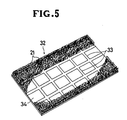
- Figure 5 shows a further modification in which a looped fastener sheet 32 has a plurality of positioning reference lines 33 appearing on the face of a foundation fabric 34.
- the printing plate 11 Figure 2 can be accurately positioned on the plate cylinder 10 with utmost ease.
- the fastener sheet 18, 27, 31, or 32 may have hook-shaped interlocking elements, in which instance the fastener sheet 19 on the printing plate 11 has loop-shaped interlocking elements.
Landscapes
- Engineering & Computer Science (AREA)
- Mechanical Engineering (AREA)
- Supply, Installation And Extraction Of Printed Sheets Or Plates (AREA)
- Perforating, Stamping-Out Or Severing By Means Other Than Cutting (AREA)
Applications Claiming Priority (2)
| Application Number | Priority Date | Filing Date | Title |
|---|---|---|---|
| JP201265/86U | 1986-12-27 | ||
| JP1986201265U JPS63106637U (de) | 1986-12-27 | 1986-12-27 |
Publications (2)
| Publication Number | Publication Date |
|---|---|
| EP0279947A2 true EP0279947A2 (de) | 1988-08-31 |
| EP0279947A3 EP0279947A3 (de) | 1990-01-17 |
Family
ID=16438083
Family Applications (1)
| Application Number | Title | Priority Date | Filing Date |
|---|---|---|---|
| EP87119120A Withdrawn EP0279947A3 (de) | 1986-12-27 | 1987-12-23 | Vorrichtung zum Befestigen von Druckplatten auf einen Formzylinder einer Druckmaschine |
Country Status (4)
| Country | Link |
|---|---|
| EP (1) | EP0279947A3 (de) |
| JP (1) | JPS63106637U (de) |
| KR (1) | KR920007068Y1 (de) |
| MY (1) | MY101538A (de) |
Cited By (3)
| Publication number | Priority date | Publication date | Assignee | Title |
|---|---|---|---|---|
| US5622113A (en) * | 1995-09-28 | 1997-04-22 | Goss Graphic Systems, Inc. | Gripping surface for cutting cylinders in a folding machine |
| WO2016007892A1 (en) * | 2014-07-10 | 2016-01-14 | Velcro Industries B.V. | Printing plate connection systems |
| WO2017129702A1 (fr) | 2016-01-27 | 2017-08-03 | Bricq | Dispositif comprenant un cylindre d'entraînement et un revêtement auto-agrippant, procédé et machine associés |
Family Cites Families (2)
| Publication number | Priority date | Publication date | Assignee | Title |
|---|---|---|---|---|
| US3568596A (en) * | 1969-03-06 | 1971-03-09 | Jimmie N Mashburn | Releasable attaching means for printing plates and other dies |
| DE8510276U1 (de) * | 1985-04-06 | 1985-08-14 | Ophey, Jens, 3352 Einbeck | Druckwalze |
-
1986
- 1986-12-27 JP JP1986201265U patent/JPS63106637U/ja active Pending
-
1987
- 1987-12-23 EP EP87119120A patent/EP0279947A3/de not_active Withdrawn
- 1987-12-23 MY MYPI87003242A patent/MY101538A/en unknown
- 1987-12-26 KR KR2019870023406U patent/KR920007068Y1/ko not_active Expired
Cited By (6)
| Publication number | Priority date | Publication date | Assignee | Title |
|---|---|---|---|---|
| US5622113A (en) * | 1995-09-28 | 1997-04-22 | Goss Graphic Systems, Inc. | Gripping surface for cutting cylinders in a folding machine |
| WO2016007892A1 (en) * | 2014-07-10 | 2016-01-14 | Velcro Industries B.V. | Printing plate connection systems |
| EP3166793A4 (de) * | 2014-07-10 | 2018-02-28 | Velcro Bvba | Druckplattenverbindungssysteme |
| US10518525B2 (en) | 2014-07-10 | 2019-12-31 | Velcro BVBA | Printing plate connection systems |
| WO2017129702A1 (fr) | 2016-01-27 | 2017-08-03 | Bricq | Dispositif comprenant un cylindre d'entraînement et un revêtement auto-agrippant, procédé et machine associés |
| CN109070520A (zh) * | 2016-01-27 | 2018-12-21 | 布利克输送带公司 | 包括进给辊和自粘紧固件的设备及相关的方法和机器 |
Also Published As
| Publication number | Publication date |
|---|---|
| KR880011886U (ko) | 1988-08-26 |
| JPS63106637U (de) | 1988-07-09 |
| EP0279947A3 (de) | 1990-01-17 |
| KR920007068Y1 (ko) | 1992-10-02 |
| MY101538A (en) | 1991-11-30 |
Similar Documents
| Publication | Publication Date | Title |
|---|---|---|
| KR100225013B1 (ko) | 필름 인화 방법 및 필름 이송 장치 | |
| US8172975B2 (en) | Thermal transfer media and method of making and using same | |
| US4441423A (en) | Collect-printing unit for security printing for use in a rotary printing press | |
| US20230147373A1 (en) | Image transfer sheet, manufacturing method for image transfer sheet, and image transfer method | |
| EP0279947A2 (de) | Vorrichtung zum Befestigen von Druckplatten auf einen Formzylinder einer Druckmaschine | |
| EP0325803A1 (de) | Drucker | |
| NZ195199A (en) | Applying an unobtrusive image to paper by charged droplet printing | |
| CA2077871C (en) | A foil as a covering for an impression cylinder in rotary offset perfecting presses | |
| US4198451A (en) | Marker layup | |
| EP0547753B1 (de) | Offsetdruckmaschine | |
| US7444933B2 (en) | Stencil printer | |
| EP0739752B1 (de) | Siebdruckform | |
| CZ299949B6 (cs) | Zarízení pro vysekávání, žlábkování, perforování nebo reliéfní ražení | |
| JP2729992B2 (ja) | 転写記録方法,転写記録装置及び転写シート | |
| KR100241105B1 (ko) | 현수막 제작 방법 | |
| EP0904937B1 (de) | Schablonendruckverfahren und Vorrichtung | |
| JP2001191484A (ja) | スキージ装置、スクリーン印刷方法、ロータリースクリーン印刷方法、および孔版印刷方法 | |
| JP3000506U (ja) | 印刷機用複層布地 | |
| EP0553626B1 (de) | Verfahren zum Hochdrucken sowie Vorrichtung zum Durchführen des Verfahrens | |
| JP3776725B2 (ja) | 熱転写プリンター、熱転写記録方法及び熱転写受像シートロール | |
| US3893714A (en) | Business sheet having removable transfer means and method of making | |
| JPS6048355A (ja) | ベルト式印刷装置 | |
| JPS60139882A (ja) | 転写捺染法 | |
| JPH065457B2 (ja) | ラベルの製造装置 | |
| US20080053328A1 (en) | Printing method and apparatus |
Legal Events
| Date | Code | Title | Description |
|---|---|---|---|
| PUAI | Public reference made under article 153(3) epc to a published international application that has entered the european phase |
Free format text: ORIGINAL CODE: 0009012 |
|
| AK | Designated contracting states |
Kind code of ref document: A2 Designated state(s): DE FR GB IT |
|
| PUAL | Search report despatched |
Free format text: ORIGINAL CODE: 0009013 |
|
| AK | Designated contracting states |
Kind code of ref document: A3 Designated state(s): DE FR GB IT |
|
| 17P | Request for examination filed |
Effective date: 19900411 |
|
| 17Q | First examination report despatched |
Effective date: 19910923 |
|
| STAA | Information on the status of an ep patent application or granted ep patent |
Free format text: STATUS: THE APPLICATION IS DEEMED TO BE WITHDRAWN |
|
| 18D | Application deemed to be withdrawn |
Effective date: 19920204 |