EP0280104B1 - Compteur mécanique à tambours - Google Patents
Compteur mécanique à tambours Download PDFInfo
- Publication number
- EP0280104B1 EP0280104B1 EP88101772A EP88101772A EP0280104B1 EP 0280104 B1 EP0280104 B1 EP 0280104B1 EP 88101772 A EP88101772 A EP 88101772A EP 88101772 A EP88101772 A EP 88101772A EP 0280104 B1 EP0280104 B1 EP 0280104B1
- Authority
- EP
- European Patent Office
- Prior art keywords
- switching
- magnet
- rocker
- counting device
- drum
- Prior art date
- Legal status (The legal status is an assumption and is not a legal conclusion. Google has not performed a legal analysis and makes no representation as to the accuracy of the status listed.)
- Expired - Lifetime
Links
Images
Classifications
-
- G—PHYSICS
- G06—COMPUTING OR CALCULATING; COUNTING
- G06M—COUNTING MECHANISMS; COUNTING OF OBJECTS NOT OTHERWISE PROVIDED FOR
- G06M1/00—Design features of general application
- G06M1/08—Design features of general application for actuating the drive
- G06M1/10—Design features of general application for actuating the drive by electric or magnetic means
- G06M1/102—Design features of general application for actuating the drive by electric or magnetic means by magnetic or electromagnetic means
Definitions
- the invention relates to a mechanical roller counter with a ratchet mechanism on the ratchet wheel for the initial roller and incrementing the number rollers according to the preamble of claim 1.
- Roller counters with mechanical or electromechanical drive are known. These are used to record quantities, parts, quantities, lengths or movements.
- the output force for the display rollers is transmitted via shafts, levers, gears and the like.
- Mechanical components In the known electromechanical counters, the driving force is supplied in the form of electrical energy and converted into mechanical energy in the counter for actuating the number rollers, e.g. according to DE-PS 35 11 870, DE-GM 83 30 263 and DE-GM 19 35 240.
- the invention has for its object to provide a particularly reliable and inexpensive counter with a low overall height, which can be used on site even in extremely unfavorable conditions, such as in plant construction and in hydraulically operated machines is to be driven without contact without electrical connections or electrical energy supply.
- the counter according to the preamble of claim 1 is characterized in that the rocker carries a permanent magnet on at least one side and is preferably held in the rest position under the action of a holding magnet or ferromagnetic part and / or a spring, such that when approaching of a ferromagnetic or magnetic switching part, the coil-free magnetic rocker tilts while advancing the ratchet wheel and thereby causes the counting without supplying electrical energy.
- a rocker can be used with permanent magnets on one side and counterweight on the other, as well as a return spring and ferromagnetic switching part or, as preferably described below, the rocker can accommodate permanent magnets on both sides and interact with a ferromagnetic holding and a magnetic switching part.
- the drive takes place via permanent magnetic fields which do not react negatively to environmental influences such as dirt, liquids, gases, light, noise and vibrations.
- the permanent magnets are preferably hermetically sealed, the switching part being located, for example, on the piston of a pneumatic cylinder made of non-magnetic material. The material selection from the counter and the auxiliary devices must be coordinated with the magnetic functions.
- a permanent magnet with an opposite pole arrangement can be provided on both sides symmetrically to the axis of rotation, such that when a switching magnet arranged outside the counter approaches, the one permanent magnet is attracted and the other is repelled, whereby an increased switching force is achieved.
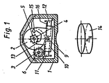
- the housing 1 serves to accommodate and store the set of rollers, consisting of number rollers 2 with indexing drives 3 and star wheel 4 for the initial roller and the two parallel shafts 5 and 6, and the two end plates 7 and 8.
- the shaft 9 supports the magnetic rocker 10 with the two to this (10) symmetrically arranged permanent magnets 11 and 12.
- the rocker 10 is held in the rest position by the shaft 6 as a ferromagnetic part.
- the pawl 13 engages in the switching star 4.
- the magnetic rocker 10 When the switching magnet 14 approaches, the magnetic rocker 10 is tilted in accordance with FIG. 2 due to the torque which increases counterclockwise compared to the holding torque.
- the first half step for switching on is effected by means of the switching pawl 15, while the second switching step occurs when the rocker 10 is tilted back in Rest position when the switching magnet 14 is removed, which means that the starting position for the next sequence of movements is reached.
- a magnetic yoke 16 can furthermore reduce scatter losses which occur and thus serve to strengthen the magnetic field in the working area.
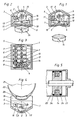
- FIG. 3 shows a top view of the open counter and FIG. 4 shows a side view
- FIG. 5 shows a partial section through the pneumatic drive.
- the bearing of the roller set 2 to 6 between the plates 7 and 8 with the ends of the shafts 5 and 6 in the perforation 17 and the slot 18 in the housing 1 can be seen.
- the shoulder 19 running in the direction of the rocker 10 with bar 20 on the housing 1 can be seen, which serves to fix the counter on the pneumatic cylinder 21 by means of anti-magnetic strips 22.
- the switching magnet 14 for actuating the counter on the piston 23 is arranged between the seals 24.
Landscapes
- Physics & Mathematics (AREA)
- Electromagnetism (AREA)
- General Physics & Mathematics (AREA)
- Engineering & Computer Science (AREA)
- Theoretical Computer Science (AREA)
- Transmission Devices (AREA)
- Color Electrophotography (AREA)
- Valve Device For Special Equipments (AREA)
- Golf Clubs (AREA)
- Valve-Gear Or Valve Arrangements (AREA)
Claims (8)
- Compteur mécanique à rouleaux, comprenant une commande à cliquets (10, 13, 15) sur la roue à rochet (4) pour le rouleaux de début et l'avancement des rouleaux de chiffres (2) , l'entraînement des doigts d'encliquetage (13, 15) s'effectuant au moyen d'une bascule (10) montée de manière pivotante, caractérisé en ce que la bascule (10) porte au moins sur un côté un aimant permanent (11, 12) et qu'elle est maintenue dans la position de repos, de préférence par l'action d'un aimant de maintien ou d'un élément ferromagnétique (6) et/ou d'un ressort, de manière que lors du rapprochement d'un élément de commutation ferromagnétique ou magnétique (14) , la bascule magnétique (10) sans bobine bascule avec avancement de la roue à rochet (4) et provoque ainsi l'avancement d'un pas de comptage sans amenée d'énergie électrique.
- Compteur mécanique à rouleaux selon la revendication 1, caractérisé en ce que symétriquement de part et d'autre de l'axe de rotation (9) est prévu respectivement un aimant permanent (11, 12) en disposition antipolaire, de sorte que lors du rapprochement d'un aimant de commutation (14) disposé à l'extérieur du compteur, l'un des aimants permanents (11) est attiré, tandis que l'autre (12) est repoussé.
- Compteur mécanique à rouleaux selon l'une des revendications 1 ou 2, caractérisé en ce que les aimants permanents (11, 12) sont disposés symétriquement par rapport à l'axe de du palier (9) de la bascule magnétique (10).
- Compteur mécanique à rouleaux selon l'une des revendications 1 à 3, caractérisé en ce que les courts doigts d'encliquetage (13, 15) sont conformés en une seule pièce sur la bascule magnétique (10), et que la bascule magnétique (10) est de préférence maintenue dans la position de repos par l'attraction d'un aimant contre la broche (6).
- Compteur mécanique à rouleaux selon l'une des revendications 2 à 4, caractérisé en ce que les aimants permanents (11, 12) sont reliés magnétiquement à une culasse magnétique (16).
- Compteur mécanique à rouleaux selon l'une des revendications précédentes, caractérisé en ce que le jeu de rouleaux (2 à 6) préfabriqué maintenu entre deux platines (7, 8) peut être introduit, en tant que sous-ensemble composé de rouleaux de chiffres (2), de commandes d'avancement (3) et de la commande magnétique (6), dans un boîtier (1) hermétiquement étanche et dépourvu de branchements électriques.
- Compteur mécanique à rouleaux selon la revendication 6, caractérisé en ce que le boîtier (1) présente une réduction (19) avec baguette (20) qui s'étend en direction de la bascule (10) et sert à la fixation du compteur sur la pièce de machine (21) considérée, au moyen de bandes antimagnétiques (22).
- Compteur mécanique à rouleaux selon l'une des revendications précédentes, caractérisé en ce que l'aimant de commutation (14) est associé à un élément mobile, par exemple un piston (23) d'une machine pour le comptage du nombre de courses ou analogues.
Priority Applications (1)
| Application Number | Priority Date | Filing Date | Title |
|---|---|---|---|
| AT88101772T ATE77501T1 (de) | 1987-02-25 | 1988-02-08 | Mechanisches rollenzaehlwerk. |
Applications Claiming Priority (2)
| Application Number | Priority Date | Filing Date | Title |
|---|---|---|---|
| DE3705962 | 1987-02-25 | ||
| DE19873705962 DE3705962A1 (de) | 1987-02-25 | 1987-02-25 | Mechanisches rollenzaehlwerk |
Publications (3)
| Publication Number | Publication Date |
|---|---|
| EP0280104A2 EP0280104A2 (fr) | 1988-08-31 |
| EP0280104A3 EP0280104A3 (en) | 1989-09-20 |
| EP0280104B1 true EP0280104B1 (fr) | 1992-06-17 |
Family
ID=6321691
Family Applications (1)
| Application Number | Title | Priority Date | Filing Date |
|---|---|---|---|
| EP88101772A Expired - Lifetime EP0280104B1 (fr) | 1987-02-25 | 1988-02-08 | Compteur mécanique à tambours |
Country Status (3)
| Country | Link |
|---|---|
| EP (1) | EP0280104B1 (fr) |
| AT (1) | ATE77501T1 (fr) |
| DE (2) | DE3705962A1 (fr) |
Cited By (13)
| Publication number | Priority date | Publication date | Assignee | Title |
|---|---|---|---|---|
| US6561384B2 (en) | 1998-01-16 | 2003-05-13 | 1263152 Ontario Inc. | Medicament dispensing device and method for the use thereof |
| US6729330B2 (en) | 1998-05-05 | 2004-05-04 | Trudell Medical International | Indicating device for aerosol container |
| US6745760B2 (en) | 2001-05-15 | 2004-06-08 | Trudell Medical International | Medicament applicator |
| US6761161B2 (en) | 1998-05-05 | 2004-07-13 | Trudell Medical International | Indicating device |
| US7004164B2 (en) | 2002-03-21 | 2006-02-28 | Trudell Medical International | Indicating device for aerosol container |
| US7100530B2 (en) | 2003-12-15 | 2006-09-05 | Trudell Medical International, Inc. | Dose indicating device |
| US7543582B2 (en) | 2004-09-20 | 2009-06-09 | Trudell Medical International | Dose indicating device with display elements attached to container |
| US7621273B2 (en) | 2003-10-28 | 2009-11-24 | Trudell Medical International | Indicating device with warning dosage indicator |
| US7743945B2 (en) | 2005-01-20 | 2010-06-29 | Trudell Medical International | Dispensing device |
| US8082873B2 (en) | 2008-05-05 | 2011-12-27 | Trudell Medical International | Drive mechanism for an indicating device |
| US8141550B2 (en) | 2006-08-01 | 2012-03-27 | Trudell Medical International | Dispensing device |
| US8181591B1 (en) | 2008-05-23 | 2012-05-22 | Trudell Medical International | Domed actuator for indicating device |
| US8596265B2 (en) | 2008-10-22 | 2013-12-03 | Trudell Medical International | Modular aerosol delivery system |
Families Citing this family (1)
| Publication number | Priority date | Publication date | Assignee | Title |
|---|---|---|---|---|
| TW533865U (en) | 1997-06-10 | 2003-05-21 | Glaxo Group Ltd | Dispenser for dispensing medicament and actuation indicating device |
Family Cites Families (5)
| Publication number | Priority date | Publication date | Assignee | Title |
|---|---|---|---|---|
| DE1935240U (de) * | 1963-01-23 | 1966-03-24 | Hengstler K G Zaehlerfabrik J | Elektro-mechanischer impulszaehler mit ankergangschaltung und federndem uebertragungsglied. |
| CH444761A (fr) * | 1965-12-10 | 1968-02-29 | Ebauches Sa | Dispositif magnétique d'entraînement pour l'horlogerie |
| DE1954623B2 (de) * | 1969-10-30 | 1973-02-15 | Siemens AG, 1000 Berlin u 8000 München | Ziffernsteller unter verwendung magnetfeldabhaengiger widerstaende |
| AT377110B (de) * | 1981-10-29 | 1985-02-11 | Mattig Kg Anton | Elektromechanisches zaehlwerk |
| DE3511870C1 (de) * | 1985-04-01 | 1986-06-26 | J. Hengstler Kg, 7209 Aldingen | Impulszaehler als elektromechanisches Zaehlwerk mit Schwingspulenantrieb |
-
1987
- 1987-02-25 DE DE19873705962 patent/DE3705962A1/de active Granted
-
1988
- 1988-02-08 AT AT88101772T patent/ATE77501T1/de not_active IP Right Cessation
- 1988-02-08 DE DE8888101772T patent/DE3871981D1/de not_active Expired - Fee Related
- 1988-02-08 EP EP88101772A patent/EP0280104B1/fr not_active Expired - Lifetime
Cited By (46)
| Publication number | Priority date | Publication date | Assignee | Title |
|---|---|---|---|---|
| US6561384B2 (en) | 1998-01-16 | 2003-05-13 | 1263152 Ontario Inc. | Medicament dispensing device and method for the use thereof |
| US9649455B2 (en) | 1998-01-16 | 2017-05-16 | Trudell Medical International | Indicating device |
| US8944285B2 (en) | 1998-01-16 | 2015-02-03 | Trudell Medical International | Indicating device |
| US8505773B2 (en) | 1998-01-16 | 2013-08-13 | Trudell Medical International | Indicating device |
| US8157128B2 (en) | 1998-01-16 | 2012-04-17 | Trudell Medical International | Indicating device |
| US6938796B2 (en) | 1998-01-16 | 2005-09-06 | 1263152 Ontario Inc. | Indicating device |
| US7984826B2 (en) | 1998-01-16 | 2011-07-26 | Trudell Medical International | Indicating device |
| US6997349B2 (en) | 1998-01-16 | 2006-02-14 | Trudell Medical International | Indicating device |
| US7575130B2 (en) | 1998-01-16 | 2009-08-18 | Trudell Medical International | Indicating device |
| US7516738B2 (en) | 1998-05-05 | 2009-04-14 | Trudell Medical International | Indicating device |
| US6926002B2 (en) | 1998-05-05 | 2005-08-09 | Trudell Medical International | Indicating device |
| US6761161B2 (en) | 1998-05-05 | 2004-07-13 | Trudell Medical International | Indicating device |
| US8662075B2 (en) | 1998-05-05 | 2014-03-04 | Trudell Medical International | Dispensing device |
| US7568481B2 (en) | 1998-05-05 | 2009-08-04 | Trudell Medical International | Indicating device |
| US9168343B2 (en) | 1998-05-05 | 2015-10-27 | Trudell Medical International | Dispensing device |
| US6729330B2 (en) | 1998-05-05 | 2004-05-04 | Trudell Medical International | Indicating device for aerosol container |
| US8074643B2 (en) | 1998-05-05 | 2011-12-13 | Trudell Medical International | Dispensing device |
| US6953039B2 (en) | 1998-05-05 | 2005-10-11 | Trudell Medical International | Medicament dispensing device |
| US7650883B2 (en) | 1998-05-05 | 2010-01-26 | Trudell Medical International | Dispensing device |
| US7341057B2 (en) | 1998-05-05 | 2008-03-11 | Trudell Medical International | Indicating device |
| US7757688B2 (en) | 1998-05-05 | 2010-07-20 | Trudell Medical International | Dispensing device |
| US6745760B2 (en) | 2001-05-15 | 2004-06-08 | Trudell Medical International | Medicament applicator |
| US8327847B2 (en) | 2002-03-21 | 2012-12-11 | Trudell Medical International | Indicating device for aerosol container |
| US7597102B2 (en) | 2002-03-21 | 2009-10-06 | Trudell Medical International | Indicating device for aerosol container |
| US7004164B2 (en) | 2002-03-21 | 2006-02-28 | Trudell Medical International | Indicating device for aerosol container |
| US7621273B2 (en) | 2003-10-28 | 2009-11-24 | Trudell Medical International | Indicating device with warning dosage indicator |
| US9968748B2 (en) | 2003-10-28 | 2018-05-15 | Trudell Medical International | Indicating device with warning dosage indicator |
| US8578934B2 (en) | 2003-10-28 | 2013-11-12 | Trudell Medical International | Indicating device with warning dosage indicator |
| US8074594B2 (en) | 2003-12-15 | 2011-12-13 | Trudell Medical International | Dose indicating device |
| US7584712B2 (en) | 2003-12-15 | 2009-09-08 | Trudell Medical International | Dose indicating device |
| US7100530B2 (en) | 2003-12-15 | 2006-09-05 | Trudell Medical International, Inc. | Dose indicating device |
| US8869735B2 (en) | 2003-12-15 | 2014-10-28 | Trudell Medical International, Inc. | Dose indicating device |
| US8079362B2 (en) | 2004-09-20 | 2011-12-20 | Trudell Medical International | Method for displaying dosage indicia |
| US7543582B2 (en) | 2004-09-20 | 2009-06-09 | Trudell Medical International | Dose indicating device with display elements attached to container |
| US7743945B2 (en) | 2005-01-20 | 2010-06-29 | Trudell Medical International | Dispensing device |
| US8973784B2 (en) | 2005-01-20 | 2015-03-10 | Trudell Medical International | Dispensing device |
| US9656032B2 (en) | 2005-01-20 | 2017-05-23 | Trudell Medical International | Dispensing device |
| US7886934B2 (en) | 2005-01-20 | 2011-02-15 | Trudell Medical International | Dispensing device |
| US8141550B2 (en) | 2006-08-01 | 2012-03-27 | Trudell Medical International | Dispensing device |
| US9265901B2 (en) | 2006-08-01 | 2016-02-23 | Trudell Medical International | Dispensing device |
| US10950149B2 (en) | 2006-08-01 | 2021-03-16 | Trudell Medical International | Dispensing device |
| US8082873B2 (en) | 2008-05-05 | 2011-12-27 | Trudell Medical International | Drive mechanism for an indicating device |
| US8181591B1 (en) | 2008-05-23 | 2012-05-22 | Trudell Medical International | Domed actuator for indicating device |
| US8596265B2 (en) | 2008-10-22 | 2013-12-03 | Trudell Medical International | Modular aerosol delivery system |
| US9032953B2 (en) | 2008-10-22 | 2015-05-19 | Trudell Medical International | Modular aerosol delivery system |
| US9242057B2 (en) | 2008-10-22 | 2016-01-26 | Trudell Medical International | Modular aerosol delivery system |
Also Published As
| Publication number | Publication date |
|---|---|
| DE3871981D1 (de) | 1992-07-23 |
| EP0280104A3 (en) | 1989-09-20 |
| ATE77501T1 (de) | 1992-07-15 |
| DE3705962A1 (de) | 1988-09-08 |
| EP0280104A2 (fr) | 1988-08-31 |
| DE3705962C2 (fr) | 1988-12-01 |
Similar Documents
| Publication | Publication Date | Title |
|---|---|---|
| EP0280104B1 (fr) | Compteur mécanique à tambours | |
| EP2088264B1 (fr) | Dispositif pour actioner un élément de fermeture, pourvu d'un générateur électrique | |
| DE102008043136A1 (de) | Schlaghammer mit linearmotorischem Antrieb | |
| DE2903817A1 (de) | Elektromagnetische kolbenpumpe fuer fluessige und gasfoermige medien | |
| EP0078787B1 (fr) | Compteur électromécanique pour l'addition ou soustraction numérique en continu | |
| CH363078A (de) | Gleichstommaschine nach dem Magnetmotor-Prinzip mit einem Läufer aus Dauermagnetwerkstoff | |
| EP0196581B1 (fr) | Compteur d'impulsions sous forme de compteur électromécanique entraîné par un mécanisme de bobine oscillante | |
| DE3103744A1 (de) | Anzeigevorrichtung fuer die wegstreckenmessung von fahrzeugen | |
| DE3409182A1 (de) | Magnetisches antriebssystem | |
| DE2757594A1 (de) | Elektromagnetische kolbenpumpe fuer fluessige und gasfoermige medien | |
| DE974497C (de) | Vorrichtung zum Erzeugen von Schwing- oder Ruettelbewegungen | |
| DE1072204B (fr) | ||
| DE628994C (de) | Elektrischer Schwingankermotor | |
| DE923734C (de) | Elektrische Einrichtung zur Erzeugung einer Dreh- oder Umlaufbewegung durch aufeinanderfolgende Stromimpulse wechselnder Richtung | |
| DE102016115053A1 (de) | Elektrische Energiespeichervorrichtung und Elektrogerät | |
| DE2051764A1 (de) | Anordnung zur Umwandlung einer hin- und hergehenden Bewegung eines ersten Apparateteiles in eine schrittweise Drehbewegung bestimmter Drehrichtung eines zweiten Apparateteiles | |
| DE479335C (de) | Schwingende bzw. oszillierende, elektrische Maschine mit konstantem Luftspalt zur Leistungsuebertragung | |
| DE1202604B (de) | Anordnung zur Umwandlung einer Schwingbewegung in eine Drehbewegung | |
| DE151601C (fr) | ||
| AT61447B (de) | Empfänger für elektrische Signalübertragung. | |
| DE1273876C2 (de) | Anordnung zum wahlweisen Antrieb jeweils eines Zaehlwerks aus einer Gruppe von mehr als zwei Zaehlwerken durch elektrische Impulse, insbesondere fuer Mehrtarif-Fernzaehlwerke | |
| AT144268B (de) | Elektromagnetischer Schwingankermotor. | |
| EP3855608A1 (fr) | Convertisseur permettant de convertir l'énergie mécanique en énergie électrique | |
| DE2040291A1 (de) | Antriebssystem fuer ein bistabiles magnetisches Relais | |
| DE3027557A1 (de) | Mit gleichstrom betriebene kolben-arbeitsmaschine |
Legal Events
| Date | Code | Title | Description |
|---|---|---|---|
| PUAI | Public reference made under article 153(3) epc to a published international application that has entered the european phase |
Free format text: ORIGINAL CODE: 0009012 |
|
| AK | Designated contracting states |
Kind code of ref document: A2 Designated state(s): AT BE CH DE ES FR GB GR IT LI NL |
|
| PUAL | Search report despatched |
Free format text: ORIGINAL CODE: 0009013 |
|
| AK | Designated contracting states |
Kind code of ref document: A3 Designated state(s): AT BE CH DE ES FR GB GR IT LI NL |
|
| 17P | Request for examination filed |
Effective date: 19891012 |
|
| 17Q | First examination report despatched |
Effective date: 19911104 |
|
| GRAA | (expected) grant |
Free format text: ORIGINAL CODE: 0009210 |
|
| AK | Designated contracting states |
Kind code of ref document: B1 Designated state(s): AT BE CH DE ES FR GB GR IT LI NL |
|
| PG25 | Lapsed in a contracting state [announced via postgrant information from national office to epo] |
Ref country code: IT Free format text: LAPSE BECAUSE OF FAILURE TO SUBMIT A TRANSLATION OF THE DESCRIPTION OR TO PAY THE FEE WITHIN THE PRE;WARNING: LAPSES OF ITALIAN PATENTS WITH EFFECTIVE DATE BEFORE 2007 MAY HAVE OCCURRED AT ANY TIME BEFORE 2007. THE CORRECT EFFECTIVE DATE MAY BE DIFFERENT FROM THE ONE RECORDED.SCRIBED TIME-LIMIT Effective date: 19920617 Ref country code: ES Free format text: THE PATENT HAS BEEN ANNULLED BY A DECISION OF A NATIONAL AUTHORITY Effective date: 19920617 Ref country code: BE Effective date: 19920617 Ref country code: GR Free format text: LAPSE BECAUSE OF FAILURE TO SUBMIT A TRANSLATION OF THE DESCRIPTION OR TO PAY THE FEE WITHIN THE PRESCRIBED TIME-LIMIT Effective date: 19920617 Ref country code: NL Effective date: 19920617 |
|
| REF | Corresponds to: |
Ref document number: 77501 Country of ref document: AT Date of ref document: 19920715 Kind code of ref document: T |
|
| REF | Corresponds to: |
Ref document number: 3871981 Country of ref document: DE Date of ref document: 19920723 |
|
| ET | Fr: translation filed | ||
| GBT | Gb: translation of ep patent filed (gb section 77(6)(a)/1977) | ||
| NLV1 | Nl: lapsed or annulled due to failure to fulfill the requirements of art. 29p and 29m of the patents act | ||
| PGFP | Annual fee paid to national office [announced via postgrant information from national office to epo] |
Ref country code: GB Payment date: 19930204 Year of fee payment: 6 |
|
| PLBE | No opposition filed within time limit |
Free format text: ORIGINAL CODE: 0009261 |
|
| STAA | Information on the status of an ep patent application or granted ep patent |
Free format text: STATUS: NO OPPOSITION FILED WITHIN TIME LIMIT |
|
| 26N | No opposition filed | ||
| PG25 | Lapsed in a contracting state [announced via postgrant information from national office to epo] |
Ref country code: GB Effective date: 19940208 |
|
| GBPC | Gb: european patent ceased through non-payment of renewal fee |
Effective date: 19940208 |
|
| PGFP | Annual fee paid to national office [announced via postgrant information from national office to epo] |
Ref country code: AT Payment date: 19950203 Year of fee payment: 8 |
|
| PGFP | Annual fee paid to national office [announced via postgrant information from national office to epo] |
Ref country code: CH Payment date: 19950223 Year of fee payment: 8 |
|
| PG25 | Lapsed in a contracting state [announced via postgrant information from national office to epo] |
Ref country code: AT Effective date: 19960208 |
|
| PGFP | Annual fee paid to national office [announced via postgrant information from national office to epo] |
Ref country code: FR Payment date: 19960222 Year of fee payment: 9 |
|
| PG25 | Lapsed in a contracting state [announced via postgrant information from national office to epo] |
Ref country code: LI Effective date: 19960229 Ref country code: CH Effective date: 19960229 |
|
| REG | Reference to a national code |
Ref country code: CH Ref legal event code: PL |
|
| PG25 | Lapsed in a contracting state [announced via postgrant information from national office to epo] |
Ref country code: FR Effective date: 19971030 |
|
| REG | Reference to a national code |
Ref country code: FR Ref legal event code: ST |
|
| PGFP | Annual fee paid to national office [announced via postgrant information from national office to epo] |
Ref country code: DE Payment date: 20060830 Year of fee payment: 19 |
|
| PG25 | Lapsed in a contracting state [announced via postgrant information from national office to epo] |
Ref country code: DE Free format text: LAPSE BECAUSE OF NON-PAYMENT OF DUE FEES Effective date: 20070901 |