EP0280266A1 - Porte-fils de tension - Google Patents
Porte-fils de tension Download PDFInfo
- Publication number
- EP0280266A1 EP0280266A1 EP88102706A EP88102706A EP0280266A1 EP 0280266 A1 EP0280266 A1 EP 0280266A1 EP 88102706 A EP88102706 A EP 88102706A EP 88102706 A EP88102706 A EP 88102706A EP 0280266 A1 EP0280266 A1 EP 0280266A1
- Authority
- EP
- European Patent Office
- Prior art keywords
- tension wire
- passage
- wire holder
- post
- opening
- Prior art date
- Legal status (The legal status is an assumption and is not a legal conclusion. Google has not performed a legal analysis and makes no representation as to the accuracy of the status listed.)
- Granted
Links
- 210000002105 tongue Anatomy 0.000 claims abstract description 28
- 238000003780 insertion Methods 0.000 claims abstract description 25
- 230000037431 insertion Effects 0.000 claims abstract description 25
- 239000002184 metal Substances 0.000 claims abstract description 6
- 229910000639 Spring steel Inorganic materials 0.000 claims abstract description 4
- 230000002349 favourable effect Effects 0.000 description 1
- 238000009434 installation Methods 0.000 description 1
- 239000000463 material Substances 0.000 description 1
- 210000001331 nose Anatomy 0.000 description 1
- 238000007789 sealing Methods 0.000 description 1
Images

Classifications
-
- E—FIXED CONSTRUCTIONS
- E04—BUILDING
- E04H—BUILDINGS OR LIKE STRUCTURES FOR PARTICULAR PURPOSES; SWIMMING OR SPLASH BATHS OR POOLS; MASTS; FENCING; TENTS OR CANOPIES, IN GENERAL
- E04H17/00—Fencing, e.g. fences, enclosures, corrals
- E04H17/02—Wire fencing, e.g. made of wire mesh
- E04H17/10—Wire fencing, e.g. made of wire mesh characterised by the way of connecting wire to posts; Droppers
- E04H17/124—Wire fencing, e.g. made of wire mesh characterised by the way of connecting wire to posts; Droppers connecting by one or more clamps, clips, screws, wedges or ties
Definitions
- the invention relates to a tension wire holder which can be inserted with a peg-shaped plug-in part into an opening in a post, a sheet-metal part made of spring steel having an eyelet-shaped bracket and then two plug-in tongues spread apart from one another.
- a tension wire holder of the type mentioned is described in AT-B-369 484.
- the opening in the post has a rectangular cross section and, as a result, can only be produced with great effort.
- This tension wire holder is held within the respective opening by barb-like webs, which are set up on the flat insertion tongues.
- the insertion tongues themselves are not guided on the walls of the opening.
- the distance between the ends of the barb-like webs must be measured exactly to the wall thickness of the post. As a result, the hold of this tension wire holder within an opening of the post is comparatively poor.
- DE-U-1 984 295 describes a tension wire holder in the form of a molded part.
- Such molded parts suffer from the fact that they can easily break off.
- the shape of such a molded part cannot easily be transferred to a tension wire holder made of sheet metal, since a sheet metal part has a uniform thickness everywhere.
- the object of the invention is such a design of a tension wire holder that the same is held in a circular passage with several contact points, so that a positive locking and centering is achieved within the passage.
- each insertion tongue is curved in the transverse direction and protrudes with its rear edges from a neck part and that the radius of the transverse curvature of the insertion tongues is greater than the radius of the passage .
- the invention differs from the prior art in that the transverse curvature of the insertion tongues secures four contact points within the passage.
- the rear edges which protrude from a neck part, lie against the inner wall of the post.
- the tongues are arched more strongly when inserted into the circular passage and thus slide over the edge of the circular passage.
- the insertion tongues and in particular the rear edges spring open during insertion, the rear edges clamp onto the curved inner wall of the post.
- each insertion tongue is larger than the diameter of the passage.
- a particularly favorable clamping is achieved in that the rear edges are set against the transverse curvature. This achieves increased utilization of the elasticity of the insert part and ensures that the rear edges spring back as far as possible so that they wedge like wedges on the curved inner wall of the post.
- a sealing of the opening in the post and an improvement in the seat can be achieved in that a flexible washer sits on the neck part following the bracket.
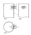
- the post 1 to 3 show a tubular post 1 of a fence system.
- the post 1 has a circular passage or a bore 2 in its wall, into which a tension wire holder 3 is inserted.
- the tension wire holder 3 is used to hold a tension wire, another wire of a mesh fence or a rod of a wire mesh mat.
- Several passages can be provided on a post for a corresponding number of tension wire holders.
- the tension wire holder 3 consists of a sheet metal strip made of stainless spring steel.
- the tension wire holder 3 has an eyelet-shaped bracket 4, on which two insertion tongues 5 are seated.
- Each insertion tongue 5 has a comparatively narrow neck part 6 and an arrow-shaped front part, the lateral legs 7 of which are widened and the rear edges 9 extend transversely from the neck part 6.
- the front part tapers out.
- Each insertion tongue, 5 is curved in the transverse direction.
- the transverse curvature of the front part with the legs 7 has a larger radius of curvature than the radius of curvature of the bore 2.
- the width of the legs 7 in the region of the rear edges 9 is comparable to the diameter of the passage 2. This width can even slightly exceed the diameter of the passage 2.
- a barbed web 8 is cut out of each tongue 5 and set up.
- the tension wire holder 3 can be inserted into the bore 2 by compressing the insertion tongues 5.
- the insertion tongues 5 are elastically deformed and arched more so that the legs 7 slide under appropriate tension through the passage 2.
- the width of the legs 7 is larger than the diameter of the passage 2, the legs can bulge along the circumference of the passage 2 without jamming occurring.
- the insertion tongues 5 spring back into the position shown in the figures, the rear edges 9 of the legs 7 and the end edge of the web 8 coming into contact with the curved inner wall of the post 1.
- the tension wire holder 3 is held in a form-fitting manner and clamps firmly on the curved inner wall.
- the tension wire holder 3 is then practically no longer detachable and holds.
- the tension wire holder 3 is mounted in such a way that the bracket 4 is placed over the respective tension wire or the respective lattice bar. Then the tension wire holder 3 is inserted into the bore 2. This enables safe and quick installation. The tension wire holder 3 can be assembled with little effort, but unauthorized dismantling and thus damage to the fence is very difficult.
- FIGS. 4 to 6 Another embodiment of the invention is shown in FIGS. 4 to 6.
- the web 8 is dispensed with.
- the rear edges 9 of the legs 7 are set against the transverse curvature, so that approximately triangular noses 10 are formed on the legs 7.
- a washer 15 made of a flexible material 15 is provided, which is placed over the neck part and bears between the bracket 4 and the post 1. This washer is used on the one hand to seal the passage 2 and on the other hand to hold the tension wire holder in the passage 2.
- the insertion tongues are elastically deformed and arched so that they slide over the inner edge of the passage 2. In the position according to FIGS.
- the legs 7 and the lugs 10 spread back so that the trailing edges 9 rest on the inner wall of the post 1. Since the inner wall is arched, the rear edges clamp onto the inner wall in a wedge shape when they spread out after passing through the passage. In this way, an extraordinarily firm hold of the tension wire holder is achieved.
Landscapes
- Engineering & Computer Science (AREA)
- Architecture (AREA)
- Civil Engineering (AREA)
- Structural Engineering (AREA)
- Fencing (AREA)
- Clamps And Clips (AREA)
- Catching Or Destruction (AREA)
Priority Applications (1)
| Application Number | Priority Date | Filing Date | Title |
|---|---|---|---|
| AT88102706T ATE66042T1 (de) | 1987-02-26 | 1988-02-24 | Spanndrahthalter. |
Applications Claiming Priority (2)
| Application Number | Priority Date | Filing Date | Title |
|---|---|---|---|
| DE3706149 | 1987-02-26 | ||
| DE19873706149 DE3706149A1 (de) | 1987-02-26 | 1987-02-26 | Spanndrahthalter |
Publications (2)
| Publication Number | Publication Date |
|---|---|
| EP0280266A1 true EP0280266A1 (fr) | 1988-08-31 |
| EP0280266B1 EP0280266B1 (fr) | 1991-08-07 |
Family
ID=6321793
Family Applications (1)
| Application Number | Title | Priority Date | Filing Date |
|---|---|---|---|
| EP88102706A Expired - Lifetime EP0280266B1 (fr) | 1987-02-26 | 1988-02-24 | Porte-fils de tension |
Country Status (3)
| Country | Link |
|---|---|
| EP (1) | EP0280266B1 (fr) |
| AT (1) | ATE66042T1 (fr) |
| DE (2) | DE3706149A1 (fr) |
Cited By (5)
| Publication number | Priority date | Publication date | Assignee | Title |
|---|---|---|---|---|
| EP0937842A1 (fr) * | 1998-02-20 | 1999-08-25 | Gust. Alberts GmbH & Co. KG | Serre-fil pour poteau de clÔture |
| US6866251B2 (en) * | 2002-05-28 | 2005-03-15 | Lars Rosaen | Fencing system |
| US7500654B2 (en) | 2002-05-28 | 2009-03-10 | Lars Rosaen | Fencing system |
| ES2374385A1 (es) * | 2011-12-12 | 2012-02-16 | Alejandro PROCOARD, S.L. | Poste para un cerramiento metálico y cerramiento correspondiente. |
| ES2374487A1 (es) * | 2011-12-12 | 2012-02-17 | Alejandro PROCOARD, S.L. | Dispositivo de anclaje para un cerramiento metálico y cerramiento correspondiente. |
Families Citing this family (1)
| Publication number | Priority date | Publication date | Assignee | Title |
|---|---|---|---|---|
| SE501059C2 (sv) * | 1992-03-27 | 1994-10-31 | Lars Lilja | Fästorgan för fastsättning av t ex nät eller lina vid en bärare |
Citations (3)
| Publication number | Priority date | Publication date | Assignee | Title |
|---|---|---|---|---|
| DE1684738A1 (de) * | 1968-02-02 | 1971-04-15 | Ludwig Haeberle Fa | In Rohrsaeulen fuer Drahtzaeune einsetzbare Befestigungsoese |
| US3930637A (en) * | 1974-04-12 | 1976-01-06 | Burlington Industries, Inc. | Fence and fence post assembly |
| AT369483B (de) * | 1978-08-30 | 1983-01-10 | Koch Inc Julius | Vorrichtung zur befestigung von biegsamen materialien an im abstand voneinander angeordneten, zueinander parallelen haltern |
Family Cites Families (4)
| Publication number | Priority date | Publication date | Assignee | Title |
|---|---|---|---|---|
| DE7240000U (de) * | 1973-03-01 | Hoesch Werke Ag | Befestigungselement aus Kunststoff | |
| DE1984295U (de) * | 1968-02-02 | 1968-04-25 | Ludwig Haeberle Fa | In rohrsaeulen fuer drahtzaeune einsetzbare befestigungsoese. |
| FR2452558A1 (fr) * | 1979-03-26 | 1980-10-24 | Ducros Georges | Systeme de fixation de fils de cloture sur des piquets |
| AT369484B (de) * | 1979-09-21 | 1983-01-10 | Voest Alpine Krems | Zaun- oder spalierpfahl mit mindestens einem spanndrahthalter |
-
1987
- 1987-02-26 DE DE19873706149 patent/DE3706149A1/de active Granted
-
1988
- 1988-02-24 EP EP88102706A patent/EP0280266B1/fr not_active Expired - Lifetime
- 1988-02-24 DE DE8888102706T patent/DE3864036D1/de not_active Expired - Lifetime
- 1988-02-24 AT AT88102706T patent/ATE66042T1/de not_active IP Right Cessation
Patent Citations (3)
| Publication number | Priority date | Publication date | Assignee | Title |
|---|---|---|---|---|
| DE1684738A1 (de) * | 1968-02-02 | 1971-04-15 | Ludwig Haeberle Fa | In Rohrsaeulen fuer Drahtzaeune einsetzbare Befestigungsoese |
| US3930637A (en) * | 1974-04-12 | 1976-01-06 | Burlington Industries, Inc. | Fence and fence post assembly |
| AT369483B (de) * | 1978-08-30 | 1983-01-10 | Koch Inc Julius | Vorrichtung zur befestigung von biegsamen materialien an im abstand voneinander angeordneten, zueinander parallelen haltern |
Cited By (5)
| Publication number | Priority date | Publication date | Assignee | Title |
|---|---|---|---|---|
| EP0937842A1 (fr) * | 1998-02-20 | 1999-08-25 | Gust. Alberts GmbH & Co. KG | Serre-fil pour poteau de clÔture |
| US6866251B2 (en) * | 2002-05-28 | 2005-03-15 | Lars Rosaen | Fencing system |
| US7500654B2 (en) | 2002-05-28 | 2009-03-10 | Lars Rosaen | Fencing system |
| ES2374385A1 (es) * | 2011-12-12 | 2012-02-16 | Alejandro PROCOARD, S.L. | Poste para un cerramiento metálico y cerramiento correspondiente. |
| ES2374487A1 (es) * | 2011-12-12 | 2012-02-17 | Alejandro PROCOARD, S.L. | Dispositivo de anclaje para un cerramiento metálico y cerramiento correspondiente. |
Also Published As
| Publication number | Publication date |
|---|---|
| EP0280266B1 (fr) | 1991-08-07 |
| ATE66042T1 (de) | 1991-08-15 |
| DE3864036D1 (de) | 1991-09-12 |
| DE3706149C2 (fr) | 1989-11-02 |
| DE3706149A1 (de) | 1988-09-08 |
Similar Documents
| Publication | Publication Date | Title |
|---|---|---|
| DE19581625C2 (de) | Federklemme für mit Ansatz versehene Sitzrahmen | |
| DE60001594T2 (de) | Klammer zur Befestigung von Objekten auf einer Ständerwand | |
| DE3002031A1 (de) | Halteelement fuer mindestens eine rohrleitung, insbesondere benzinleitung bei einem kraftfahrzeug | |
| DE2813484A1 (de) | Kabelband | |
| DE3910423A1 (de) | Klammerartige blechmutter fuer automatische montage | |
| DE2364819A1 (de) | Aufnahmeteil zur verwendung mit einem bolzen einer befestigungsvorrichtung | |
| DE2321814A1 (de) | Schlauchklemme | |
| EP0280266B1 (fr) | Porte-fils de tension | |
| DE2921891A1 (de) | Halteelement fuer ein oder mehrere laengliche teile | |
| DE2215707C3 (de) | Klemmeinrichtung | |
| DE20107378U1 (de) | Aneurysmenclip | |
| EP0020943A1 (fr) | Pinces de suspension pour conducteurs et faisceaux de conducteurs isolés | |
| DE2648467A1 (de) | Befestigungsklammer fuer die befestigung von glatten bolzen an plattenartigen bauteilen | |
| DE102023103212B3 (de) | Halteelement zum Fixieren der Kabel einer Photovoltaikanlage | |
| DE2417942A1 (de) | Befestigungsvorrichtung fuer rohre oder dergleichen | |
| EP0563567A1 (fr) | Anneau de sécurité | |
| DE9405363U1 (de) | Halteclip | |
| DE3632752A1 (de) | Spanndrahthalter | |
| DE9402626U1 (de) | Befestigungsclip für Leitungen, Kabel o.dgl. | |
| DE3234524C2 (de) | Schraubklemme zur Befestigung eines Schmutzfängers am Kotflügelrand eines Kraftfahrzeugs | |
| DE2329922B2 (de) | Axialschub-Sicherungsklemme | |
| DE8400998U1 (de) | Schilderträger | |
| AT376771B (de) | Loser verbindungsteil zum verbinden eines horizontal verlaufenden moebelteiles mit einem mit einer rastenschiene versehenen steher, moebelhaupt od.dgl. | |
| DE7805976U1 (de) | Kunststoff-Halteclip für elektrische Kabel, Rohrleitungen o.dgl | |
| DE9100290U1 (de) | Luftauslaß zum Einblasen von Zuluft in einen Raum |
Legal Events
| Date | Code | Title | Description |
|---|---|---|---|
| PUAI | Public reference made under article 153(3) epc to a published international application that has entered the european phase |
Free format text: ORIGINAL CODE: 0009012 |
|
| AK | Designated contracting states |
Kind code of ref document: A1 Designated state(s): AT BE CH DE FR IT LI NL |
|
| 17P | Request for examination filed |
Effective date: 19881203 |
|
| 17Q | First examination report despatched |
Effective date: 19890717 |
|
| GRAA | (expected) grant |
Free format text: ORIGINAL CODE: 0009210 |
|
| AK | Designated contracting states |
Kind code of ref document: B1 Designated state(s): AT BE CH DE FR IT LI NL |
|
| REF | Corresponds to: |
Ref document number: 66042 Country of ref document: AT Date of ref document: 19910815 Kind code of ref document: T |
|
| ITF | It: translation for a ep patent filed | ||
| REF | Corresponds to: |
Ref document number: 3864036 Country of ref document: DE Date of ref document: 19910912 |
|
| ET | Fr: translation filed | ||
| PLBE | No opposition filed within time limit |
Free format text: ORIGINAL CODE: 0009261 |
|
| STAA | Information on the status of an ep patent application or granted ep patent |
Free format text: STATUS: NO OPPOSITION FILED WITHIN TIME LIMIT |
|
| 26N | No opposition filed | ||
| PGFP | Annual fee paid to national office [announced via postgrant information from national office to epo] |
Ref country code: FR Payment date: 19931230 Year of fee payment: 7 |
|
| PGFP | Annual fee paid to national office [announced via postgrant information from national office to epo] |
Ref country code: AT Payment date: 19940214 Year of fee payment: 7 |
|
| PGFP | Annual fee paid to national office [announced via postgrant information from national office to epo] |
Ref country code: NL Payment date: 19940228 Year of fee payment: 7 |
|
| PGFP | Annual fee paid to national office [announced via postgrant information from national office to epo] |
Ref country code: BE Payment date: 19940309 Year of fee payment: 7 |
|
| PGFP | Annual fee paid to national office [announced via postgrant information from national office to epo] |
Ref country code: DE Payment date: 19940421 Year of fee payment: 7 |
|
| PGFP | Annual fee paid to national office [announced via postgrant information from national office to epo] |
Ref country code: CH Payment date: 19940531 Year of fee payment: 7 |
|
| PG25 | Lapsed in a contracting state [announced via postgrant information from national office to epo] |
Ref country code: AT Effective date: 19950224 |
|
| PG25 | Lapsed in a contracting state [announced via postgrant information from national office to epo] |
Ref country code: LI Effective date: 19950228 Ref country code: CH Effective date: 19950228 Ref country code: BE Effective date: 19950228 |
|
| BERE | Be: lapsed |
Owner name: GUST. ALBERTS G.M.B.H. & CO. K.G. Effective date: 19950228 |
|
| PG25 | Lapsed in a contracting state [announced via postgrant information from national office to epo] |
Ref country code: NL Effective date: 19950901 |
|
| PG25 | Lapsed in a contracting state [announced via postgrant information from national office to epo] |
Ref country code: FR Effective date: 19951031 |
|
| NLV4 | Nl: lapsed or anulled due to non-payment of the annual fee |
Effective date: 19950901 |
|
| PG25 | Lapsed in a contracting state [announced via postgrant information from national office to epo] |
Ref country code: DE Effective date: 19951101 |
|
| REG | Reference to a national code |
Ref country code: FR Ref legal event code: ST |
|
| PG25 | Lapsed in a contracting state [announced via postgrant information from national office to epo] |
Ref country code: IT Free format text: LAPSE BECAUSE OF NON-PAYMENT OF DUE FEES;WARNING: LAPSES OF ITALIAN PATENTS WITH EFFECTIVE DATE BEFORE 2007 MAY HAVE OCCURRED AT ANY TIME BEFORE 2007. THE CORRECT EFFECTIVE DATE MAY BE DIFFERENT FROM THE ONE RECORDED. Effective date: 20050224 |